Škoda Montážní návod Montageanleitung Fitting instructions
|
|
|
- Nela Janečková
- před 8 lety
- Počet zobrazení:
Transkript
1 1 Škoda Montážní návod Montageanleitung Fitting instructions TMB PS 026 SPOJOVACÍ - TAŽNÉ ZAÍZENÍ pro automobily Škoda Roomster (Praktik) s odnímatelným tažným ramenem ANHÄNGERKUPPLUNG für PKW Škoda Roomster (Praktik) mit demontierbarem Zugarm TRAILER COUPLING for Škoda Roomster (Praktik) Cars with Removable Towbar e8 * 94/20 * 0054
 Cars with Removable Towbar 23.4.")
2 2 RO1V 0001 VP VP ELCH Tech.P1 Primer P 146

3 3
4 4

5 5
6 6

7 7

8 8 Upozornní! TAŽNÉ ZAÍZENÍ Díl Tažné zaízení, je uren pouze k odborné montáži. Montáž vyžaduje použití speciálního náadí, dílenských píruek, a proto nesmí být tento díl prodán konenému uživateli v nenamontovaném stavu. Dležité Dodatená montáž tažného zaízení klade zvýšené nároky na chladící systém vozidla. Z tohoto dvodu je nutná výmna ásti chladícího systému dle informace uložené u servisního technika v autorizovaném servisu Škoda Auto. Tažné zaízení je ureno pro pipojení pívs do celkové hmotnosti 1200 kg (platí omezení hmotnosti pívsu dle technického prkazu vozu). Tažné zaízení je vyrobeno podle schválené dokumentace a odpovídá homologaci e8* 94/20* Všeobecné údaje Konstrukce tažného zaízení odpovídá všem eským i mezinárodním pedpism. Zaízení prošlo pevnostními zkouškami dle evropské smrnice ES 94/20. Konstrukce upínacího mechanizmu tažného ramena je chránna osvdením o zápise užitného vzoru Tažné rameno je opateno kulovým epem o prmru 50 mm dle ISO Upozornní K montáži tažného zaízení (RO1V 0001) je nutné navíc objednat v PROF SVARU tyto díly: - krytka s rámekem a 2ks odvtrávacích krytek VP (k uchycení odvtrávacích krytek jsou poteba plastové matice. Pokud dojde pi demontáži stávajících krytek k jejich poškození, objednejte je z katalogu náhradních díl. - lepicí tmel ELCH Technik P1 80 ml (R) - aktivátor Primer P146 (S) - sada elektrické instalace pro tažné zaízení VE V pípad poteby: - adaptér (z 13ti-pólové zásuvky na 7-pólovou) NE K vystižení otvoru do nárazníku použijte sadu: - prostihovací nástroj pro krytku zadního nárazníku a spony (Q) pro zafixování rámeku VP

9 Náhradní díly k sad: - náhradní tažné rameno VP náhradní zámek ovladací páky tažného ramena VP krytka otvoru zadního nárazníku VP Sada tažného zaízení (RO1V 0001) obsahuje (obr. 1) Název dílu Kus Pozice Nosník úplný s držákem zásuvky 1 A Šroub M10 x 35 4 B Tažné rameno 1 C Krytka kulového epu tažného ramena 1 D Klí k zámku upínací páky 2 E Krytka upínacího pouzdra 1 F Samolepicí štítek 50 kg 1 G Montážní návod Návod k obsluze Sada krytek (VP ) obsahuje (obr. 2) Název dílu Kus Pozice Krytka otvoru zadního nárazníku 1 H Rámeek pro upevnní krytky otvoru zadního nárazníku 1 J Odvtrávací krytka 1+1 K Prostihovací nástroj (VP ) se skládá z díl (obr. 3) Název dílu Kus Pozice Spodní oprná deska se tymi šrouby 1 L Stižná deska 1 M Horní pítlaná deska 1 N Podložka 10,5 4 O Matice M 10 4 P Svorka (je souástí sady nikoli dílem prostihovacího nástroje) 8 Q Seznam speciálního náadí Antikorozní plni ve spreji Spray Max 1K Acryl Füller (fa. Standox) Konzervaní vosk ve spreji Univerzální isti Momentový klí Dležité pokyny k montáži 9 Olakujte krytku otvoru zadního nárazníku (H) na píslušný barevný odstín dle pokyn výrobce laku. Pi lakování dodržujte zásady bezpenosti práce!
 Název dílu Kus Pozice Krytka otvoru zadního nárazníku 1 H Rámeek pro upevnní krytky otvoru zadního nárazníku 1 J Odvtrávací krytka 1+1 K Prostihovací nástroj (VP62 0401) se skládá z díl (obr.")
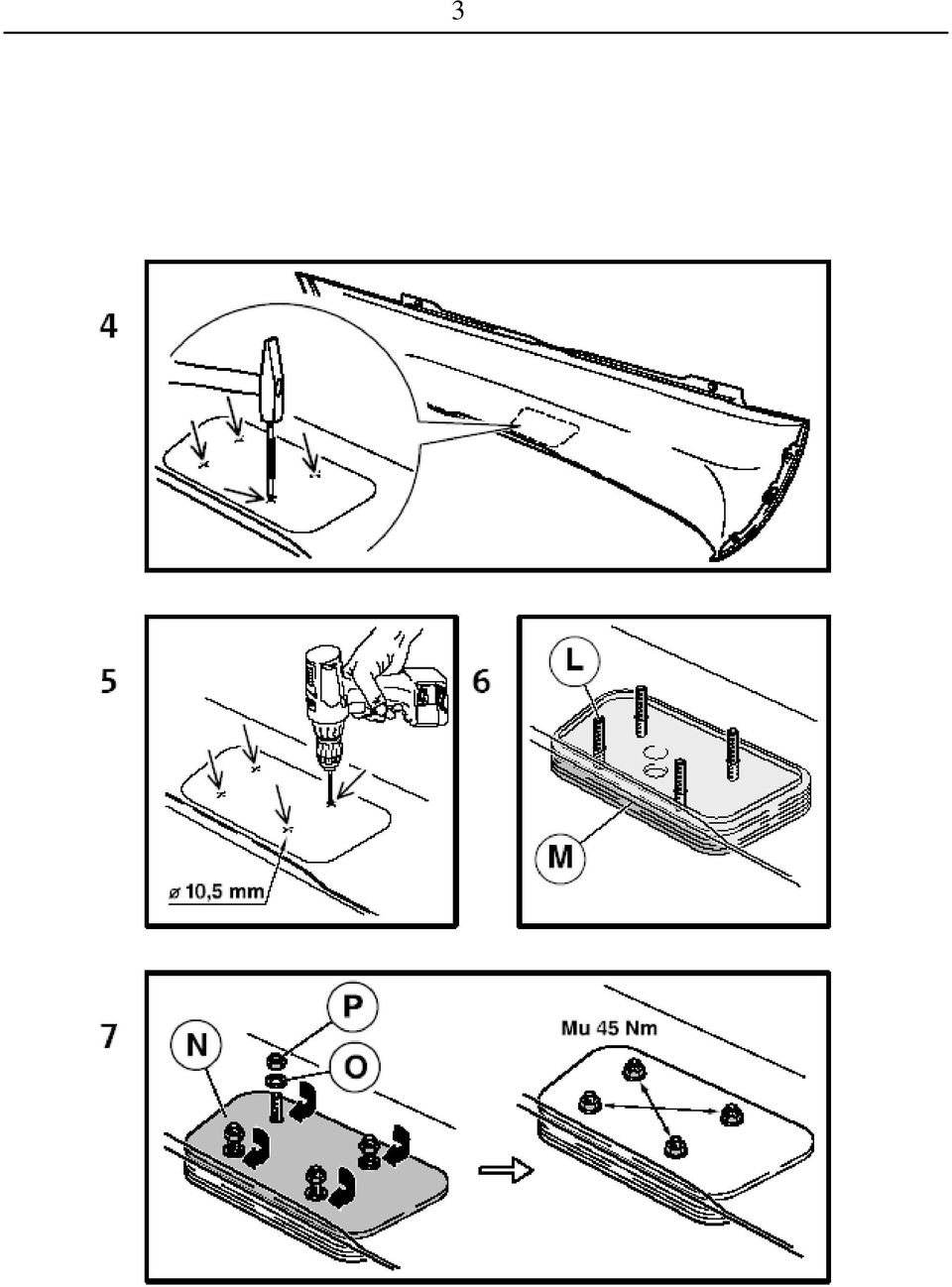
10 10 Pro zabezpeení kvalitního nalepení rámeku na zadní nárazník zajistte, aby prostorová pracovní teplota byla po celou dobu lepení rámeku a následného síování lepidla v rozmezí C. Zajistte, aby díly nebyly vystaveny pímému slunenímu záení. Pi montáži zajistte vtrání pracovišt - isticí prostedky obsahují nebezpené výpary. Postup montáže - Ustavte vozidlo na ramena dílenského zvedáku. - Demontujte zadní nárazník (lapae neistot jsou-li na vozidle), nosník zadního nárazníku a odvtrávací krytky. - Uvolnte vložky zadních blatník. Upozornní. Po demontáži nosníku nárazníku doplte v místech kontaktu nosníku nárazníku s karoserií antikorozní ochranu. Místa bez antikorozní ochrany s holým (pozinkovaným plechem) opatete dvma nástiky (min 25 mikron) antikorozního plnie ve spreji (Spray Max 1K Acryl Füller). Po vysušení plnie pi teplot cca 20 C po dobu 20 min. naneste konzervaní vosk ve spreji. Vystižení otvoru do zadního nárazníku Demontovaný zadní nárazník položte na mkkou plstnou podložku vnitní stranou smrem nahoru. - V místech pedznaených osových kíž -šipky- vyznate vhodným nástrojem stedy pro vyvrtání ty otvor V oznaených místech vyvrtejte otvory o prmru 10,5 mm. Použijte vrták do plechu (úhel hlavního ostí 180 ). Pozor na pesné umístní otvor. - 6, 7 - Rozložený prostihovací nástroj piložte na zadní nárazník následujícím zpsobem. - Na spodní oprnou desku (L) nasate stižnou desku (M) ostím nahoru (smrem k nárazníku). - Tuto sestavu piložte z vnjší (lakované) strany nárazníku tak, aby šrouby procházely vyvrtanými otvory. - Z vnitní strany nárazníku nasute na vynívající díky šroub pítlanou desku (N). - Celý komplet lehce stáhnte maticemi M 10 (P) s podložkou (O). Pozor na poškození lakované strany nárazníku.

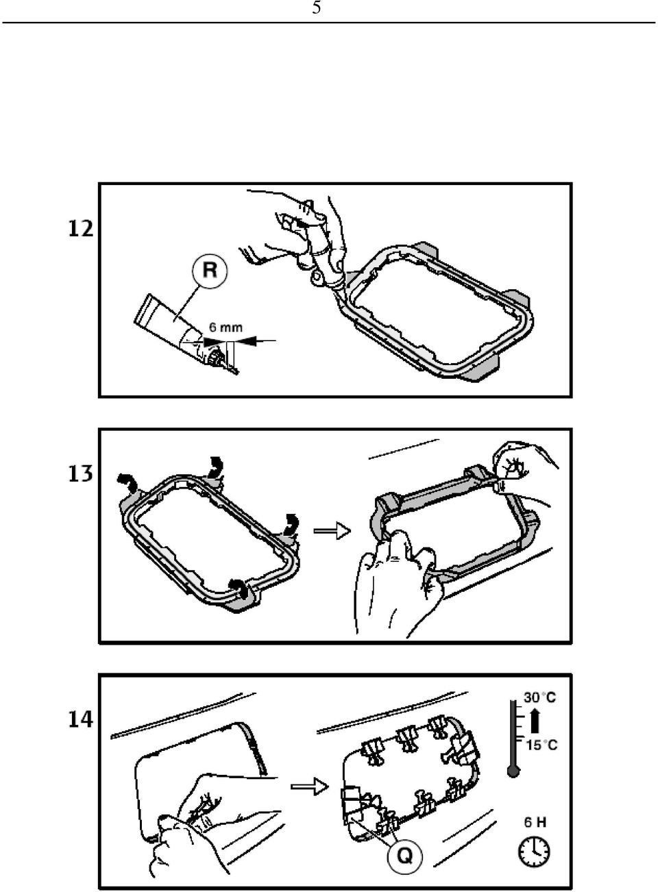
11 11 Vizuáln zkontrolujte polohu zkompletovaného prostihovacího nástroje. Popípad jemn v rámci vle mezi šrouby a pedvrtanými otvory v nárazníku jeho polohu dorovnejte vzhledem ke spodnímu okraji nárazníku. - Pokud je vše v poádku, utahujte postupn matice kížem vždy maximáln o jeden závit. Tento postup opakujte tak dlouho, až bit stižné desky dosedne na vrchní pítlanou desku. Maximální utahovací moment matic je 45 Nm. Po dotažení matic dojde k prostižení otvoru v nárazníku. - 8, Rozšroubujte matice M10 a prostihovací nástroj opatrn demontujte. Pítlanou desku odeberte smrem nahoru (od nárazníku), stižnou a oprnou desku vytáhnte z hotového otvoru smrem dol (od nárazníku). - Vhodným nástrojem vytlate vystižený díl ze stižné desky jejím prostedním otvorem -šipka-. - Vystižený otvor jemn zaistte vhodným nástrojem po celém jeho obvodu. Lepení rámeku pro uchycení krytky otvoru zadního nárazníku Lepené plochy rámeku (J) a nárazníku peliv oistte univerzálním istiem. Lepicí plochy musí být zcela zbaveny mastnoty a zbytk laku. Použití brusného papíru je nepípustné! Oištné plochy rámeku (J) a nárazníku natete (dle návodu k použití) aktivátorem Primer P146 (S). Nechte cca 10 min odvtrat. Nejpozdji do 30 min je nutné nalepit rámeek Seíznte trysku tuby lepicího tmelu (R) šikmo dle obrázku. Lepicí tmel naneste ve tvaru housenky na pipravenou plochu rámeku stedem po celém jeho obvodu. - 13, Strhnte krycí folii z oboustranné lepicí Tesa pásky na úchytech rámeku. Rámeek opatrn pilepte na vnitní stranu nárazníku tak, aby vnitní hrana rámeku kopírovala vystižený okraj otvoru nárazníku. - Polohu rámeku vizuáln zkontrolujte. Pozor. Jsou-li kolem lepeného dílu vytlaené ásti lepidla do otvoru krytky, ihned je oistte istiem. - Rámeek zafixujte na vhodných místech sponami (Q). Pozor na poškození lakované strany nárazníku. - Takto pipravený nárazník odložte na vhodné místo na dobu minimáln 6 hodin s teplotou C. Lepicí tmel musí ádn zaschnout.

12 Montáž tažného zaízení na vozidlo Strhnte záslepky otvor pro uchycení tažného zaízení na zadních podélnících (ob strany vozu) -šipky-. V pípad poteby odstrate ásti plastizolu uvnit podélník Na navaené šrouby na zadním ele vozu nasute odvtrávací krytky (K) (pozor na jejich rozlišení levá - pravá). Krytky pišroubujte plastovými maticemi Tažné zaízení (A) nasute podélnými nosníky do otvor na zadním ele vozu a ustavte jej do správné polohy. - Nosníky pišroubujte pomocí ty šroub M10 x 35 (B) k podvozku vozu. Tažné zaízení zatáhnte smrem dozadu od vozu a šrouby (stídav) na obou stranách dotáhnte utahovacím momentem 70 Nm -detail , Vyzkoušejte nasazení tažného ramena (C) do upínacího pouzdra nosníku tažného zaízení (viz. návod k obsluze tažného zaízení). - Do upínacího pouzdra nosníku tažného zaízení nasate krytku (F). Pokraujte montáží elektrické instalace tažného zaízení na vozidlo (viz. návod k montáži elektrické instalace). Po skonení montáže elektrické instalace namontujte zpt všechny demontované díly a píslušné spoje utáhnte pedepsanými utahovacími momenty Samolepicí štítek 50 kg (G) nalepte po skonení montáže nad výez v zadním nárazníku (místo ped nalepením oistte a odmastte istiem). Upozornte zákazníka na tato ustanovení - 21, Krytku otvoru zadního nárazníku nacvaknte až po dosažení dostatené pevnosti lepeného spoje (po 48 hod). - Po montáži nárazníku nezatžujte nákladovou hranu nárazníku do uplynutí 48 hod od nalepení rámeku. - Nenajíždjte s vozem na pekážky, nárazníkem se neopírejte o další vz (parkovací manévry apod). Do 48 hod od nalepení rámeku nejezdte s vozem do myky.
 na obou stranách dotáhnte utahovacím momentem 70 Nm -detail-.")
13 13 Záruní list Výrobce tažného zaízení poskytuje záruku na konstrukci, použitý materiál, výrobní provedení a funkci dodaného tažného zaízení 24 msíc od data prodeje. Reklamaci výrobku v zákonné lht uplatní kupující u prodávajícího. Oprávnnost reklamace posoudí zástupce prodávajícího spolu se zástupcem výrobce v souladu s platnými pedpisy. Podmínkou platnosti záruky je, aby tažné zaízení bylo používáno pouze k úelm, ke kterým je ureno. Kupující je povinen provit stav zboží pi jeho pevzetí. V pípad poškození zboží, nedodání ásti tažného zaízení apod. je kupující povinen tuto skutenost neprodlen ohlásit prodávajícímu a to bez zbyteného odkladu po pevzetí zboží. Všechny souásti a píslušenství tažného zaízení musí být ped odbornou montáží, zkontrolovány ve vztahu k jejich kompaktibilit na odpovídající typ vozidla. Tažná zaízení, smí být použita pouze na výrobcem uvedený typ vozidla. V pípad neodborné montáže i montáže tažného zaízení na typ vozidla, pro který není tažné zaízení ureno, neodpovídá výrobce za pípadné poškození tažného zaízení, zpsobené vadnou montáží i jeho nesprávným použitím. Prodávající odpovídá za vady, které mlo tažné zaízení pi jeho pevzetí kupujícím. Záruka se nevztahuje na škody mající pvod v bžném opotebení, v petžování a neodborném používáním tažného zaízení, dále pokud není užíváno v souladu s pokyny uvednými v návodu k obsluze. Záruka se dále nevztahuje na škody zpsobené živelnými vlivy. Prodávající rovnž neodpovídá za škodu v pípad, kdy bylo tažné zaízení zmnno i jinak upraveno. Záruka zaniká, bylo-li tažné zaízení poškozeno havárií (krom havárie vyvolané samotným tažným zaízením) nebo zásahy do jeho mechanismu a konstrukce.

14 Hinweis 14 ANHÄNGERKUPPLUNG Bauteil Anhängerkupplung, ist nur zum fachmännischen Einbau. Der Einbau verlangt Sonderwerkzeuge, Reparaturleitfäden und deshalb darf dieses Bauteil dem Endbenutzer nicht in uneingebautem Zustand verkauft werden. Wichtig Der zusätzliche Einbau von Anhängerkupplung verlangt erhöhte Forderungen für das Fahrzeug-Kühlsystem. Aus diesem Grund ist der Ersatz von einem Teil des Kühlsystems laut der beim Service-Techniker der Kundendienstwerkstatt Škoda Auto eingelegten Information erforderlich. Die Anhängerkupplung ist zum Anhängen von Anhänger bis zum Gesamtgewicht kg bestimmt (gilt die Gewichtsgrenze des Anhängers laut Fahrzeugbrief). Die Anhängerkupplung wurde gemä Zulassungsdokumentation hergestellt und entspricht der Homologation e8* 94/20* Allgemeine Daten Die Konstruktion der Anhängerkupplung entspricht allen tschechischen sowie internationalen Vorschriften. Die Anhängerkupplung hat die Festigkeitsprüfungen laut europäischer Richtlinie ES 94/20 bestanden. Die Konstruktion der Klemmeinrichtung vom Schlepparm ist durch die Beschenigung über Eintragung des Gebrauchsmusters Nr geschützt. Der Schlepparm ist mit einem Kugelzapfen von einem Durchmesser 50 mm gemä ISO 3853 versehen. Hinweis Zum Einbau der Anhängerkupplung (RO1V 0001) müssen noch zusätzlich folgende Bauteile bestellt in PROF SVAR werden: - Abdeckung mit Rahmen und 2 Stück Entlüftungsabdeckung VP (zur Befestigung der Entlüftungsabdeckungen sind Kunststoffmuttern erforderlich. Wenn beim Ausbau die bestehenden Abdeckungen beschadigt werden, bestellen Sie sie aus dem Ersatzteilkatalog) - Kleberkitt ELCH Technik P1 80 ml (R) - Primer-Aktivator P146 (S) - Elektroinstallation-Satz für Anhängerkupplung VE Bei Bedarf: - Adapter (aus der 13-poligen Steckdose auf die 7-polige) NE

15 15 Verwenden Sie zum Ausschneiden der Öffnung den Satz: - Schnittwerkzeug für die Abdeckung des Stofängers hinten und der Klammer (Q) zum Fixieren des Rahmens VP Ersatzteile zum Satz - Ersatzschlepparm VP Ersatzschloss zum Betätigungshebel des Schlepparmes VP Abdeckung für die Öffnung des Stofängers hinten VP Anhängerkupplung-Satz (RO1V 0001) beinhaltet (Abb. 1) Teilebezeichnung Stück Position Träger komplett mit Steckdosenhalter 1 A Schraube M10 x 35 4 B Schlepparm 1 C Abdeckung für Kugelzapfen des Schlepparmes 1 D Schlüssel zum Klemmhebelschloss 2 E Abdeckung für Spannhülse 1 F Selbstklebeschild 50 kg 1 G Montageanleitung Betriebsanleitung Abdeckungen-Satz (VP ) beinhaltet (Abb. 2) Teilebezeichnung Stück Position Abdeckung für die Öffnung des Stofängers hinten 1 H Rahmen zur Befestigung der Abdeckung Öffnung des Stofängers hinten 1 J Entlüftungsabdeckung 1+1 K Schnittwerkzeug (VP ) beinhaltet Teile (Abb. 3) Teilebezeichnung Stück Position Untere Stützplatte mit vier Schrauben 1 L Schnittplatte 1 M Obere Druckplatte 1 N Scheibe 10,5 4 O Mutter M 10 4 P Klammer (Bestandteil des Satzes, nicht Teil des Schnittwerkzeuges) 8 Q Verzeichnis der Sonderwerkzeuge Korrosionsschutzfüller-Spray Spray Max 1K Acryl Füller (Fa. Standox) Wachskonservierer-Spray Universalreiniger Drehmomentschlüssel
 beinhaltet (Abb.")
16 Wichtige Montagehinweise 16 Lackieren Sie die Abdeckung für die Öffnung des Stofängers hinten (H) zum entsprechenden Farbton gemä Hinweisen des Lackherstellers. Beachten Sie bei der Lackierung die Sicherheitsmanahmen! Beachten Sie, dass die Raumarbeitstemperatur während der Aufklebezeit des Rahmens und der anschlieenden Klebenetzarbeit zwischen 15-30º C beträgt, um qualitätsvolles Aufkleben des Rahmens am Stofänger hinten sicherzustellen. Sichern Sie, dass die Teile nicht der direkten Sonneneinstrahlung ausgestellt sind. Sichern Sie bei der Montage die Belüftung des Arbeitsortes Reinigungsmittel enthalten gefährliche Dämpfe. Montagereihenfolge - Stellen Sie das Fahrzeug auf die Werkstattheberarme. - Bauen Sie den Stofänger hinten (Schmutzfänger, wenn am Fahrzeug vorhanden), Stofängerträger hinten und Entlüftungsabdeckungen aus. (siehe Karosserie-Montagearbeiten Rep.-Gr. 63) - Lösen Sie die Radhausschalen hinten. Hinweis. Nach dem Ausbau des Stofängerträgers ergänzen Sie bitte Korrosionsschutz an den Berührungsstellen von Stofängerträger und Karosserie. Stellen ohne Korrosionsschutz mit reinem (verzinktem Blech) bespritzen Sie bitte zweimal (min 25 Mikronen) mit Korrosionsschutzfüller Spray (Spray Max 1K Acryl Füller). Nach der Füllertrocknung bei Temperatur ca. 20º C innerhalb 20 min. tragen Sie Wachskonservierer-Spray auf. Öffnung im Stofänger hinten ausschneiden Legen Sie den ausgebauten Stofänger hinten auf eine Filzunterlage mit der Innenseite nach oben. - Markieren Sie mit einem geeigneten Werkzeug an Stellen der vorgezeichneten Achsenkreuze -Pfeile- die Mittelpunkte zum Aufbohren der vier Öffnungen Bohren Sie an den markierten Stellen Öffnungen mit Durchmesser 10,5 mm auf. Verwenden Sie Blechbohrer (Winkel der Hauptschneide 180º). Achtung auf genaue Anbringung der Öffnungen. - 6, 7 - Legen Sie das zerlegte Schnittwerkzeug folgendermaen an den Stofänger hinten an. - Setzen Sie auf die untere Stützplatte (L) die Schnittplatte (M) mit der Schneide nach oben (Richtung zum Stofänger) auf. - Legen Sie diese Aufstellung von der Auenseite (lackierten Seite) des Stofängers so an, dass die Schrauben die aufgebohrten Öffnungen passieren.

17 17 - Setzen Sie die Druckplatte (N) von der Stofängerinnenseite auf die Schraubenschaften auf. - Ziehen Sie das ganze Komplett mit Muttern M 10 (P) und Scheibe (O) leicht zusammen. Vorsicht - Beschädigungsgefahr der lackierten Seite des Stofängers. Prüfen Sie visuell die Lage des komplettierten Schnittwerkzeuges. Berichtigen Sie gegebenenfalls fein im Rahmen des Spiels zwischen den Schrauben und vorgebohrten Öffnungen im Stofänger seine Lage angesichts der Stofänger- Unterkante. - Wenn alles in Ordnung ist, ziehen Sie die Muttern stufenweise über Kreuz immer maximal um ein Gewinde an. Wiederholen Sie diesen Vorgang so lange, bis die Schneide der Schnittplatte auf der oberen Druckplatte aufliegt. Maximaler Anzugsdrehmoment der Muttern beträgt 45 Nm. Nach dem Festziehen der Muttern wird die Öffnung im Stofänger ausgeschnitten. - 8, Schrauben Sie die Muttern M10 auf und bauen Sie das Werkzeug vorsichtig aus. Nehmen Sie die Druckplatte nach oben (vom Stofänger) ab, die Schnitt- und Stützplatte ziehen Sie aus der fertigen Öffnung nach unten (vom Stofänger) heraus. - Drücken Sie mit einem geeigneten Werkzeug das ausgeschnittene Teil aus der Schnittplatte durch die mittlere Öffnung Pfeil- heraus. - Säubern Sie mit einem geeigneten Werkzeug fein die ausgeschnittene Öffnung umlaufend. Rahmen zur Befestigung der Abdeckung Öffnung des Stofängers hinten kleben Reinigen Sie sorgfältig die Klebeflächen des Rahmens (J) und des Stofängers mit Universalreiniger. Die Klebeflächen müssen völlig entfettet und von Lackresten befreit sein. Verwendung von Schleifpapier ist nicht zulässig Streichen Sie (laut Gebrauchsanleitung) die gereinigten Flächen des Rahmens (J) und des Stofängers mit Primer-Aktivator P146 (S) ein. Lassen Sie ca. 10 Minuten entlüften. Spätestens innerhalb 30 Minuten muss der Rahmen geklebt werden Schneiden Sie die Tubendüse des Klebkitts (R) schräg zurück wie in der Abb. gezeigt. Tragen Sie Kleberkitt in Raupenform auf die vorbereitete Rahmenfläche durch die Mitte umlaufend auf. - 13, Reien Sie die Abdeckfolie vom beidseitigen Tesa-Klebeband an den Rahmenbefestigungen ab. Kleben Sie den Rahmen vorsichtig auf die

18 18 Stofängerinnenseite so, dass die Rahmeninnenkante die ausgeschnittene Kante der Stofängeröffnung kopiert. - Prüfen Sie visuell die Lage des Rahmens. Achtung. Wenn ringsum Klebeteil herausgedrückter Klebstoff in der Öffnungsabdeckung vorhanden ist, reinigen Sie es sofort mit Reiniger. - Fixieren Sie den Rahmen an den entsprechenden Stellen mit Klammern (Q). Vorsicht Beschädigungsgefahr der lackierten Seite des Stofängers. - Folgendermaen vorbereiteten Stofänger legen Sie auf geeignete Stelle für mindestens 6 Stunden bei Temperatur 15-30º C ab. Kleberkitt muss ordnungsgemä trocknen. Anhängerkupplung an das Fahrzeug montieren Reien Sie die Blindverschlüsse der Öffnungen zur Befestigung der Anhängerkupplung an den Längsträgern hinten (beide Fahrzeugseiten) Pfeile- ab. Entfernen Sie bei Bedarf die Plastisolteile in den Längsträgern innen Setzen Sie an die angeschweiten Schrauben am hinteren Fahrzeugstirn die Entlüftungsabdeckungen (K) ein (Vorsicht auf Unterscheidung links rechts). Schrauben Sie die Abdeckungen mit Kunststoffmuttern an Setzen Sie die Anhängerkupplung (A) durch die Längsträger in die Öffnungen am hinteren Fahrzeugstirn ein und richten Sie sie in die richtige Lage ein. - Schrauben Sie die Träger mit vier Schrauben M10 x 35 (B) an das Fahrwerk des Fahrzeugs an. Ziehen Sie die Anhängerkupplung nach hinten vom Fahrzeug und schrauben Sie die Schrauben (abwechselnd) auf beiden Seiten mit Anzugsdrehmoment 70 Nm Detailfest. - 18, Prüfen Sie das Einsetzen des Schlepparmes (C) in der Spannhülse des Trägers für Anhängerkupplung (siehe Betriebsanleitung der Anhängerkupplung). - Setzen Sie die Abdeckung (F) in die Spannhülse des Trägers für Anhängerkupplung ein. Fahren Sie mit der Montage der Elektroinstallation für Anhängerkupplung am Fahrzeug fort (siehe Montageanleitung der Elektroinstallation für Anhängerkupplung). Nach Beendigung der Montage der Elektroinstallation bauen Sie wieder alle ausgebauten Teile ein und ziehen Sie die entsprechenden Anschlüsse mit vorgeschriebenen Anzugsdrehmomenten an.

19 Kleben Sie das Selbstklebeschild 50 kg (G) nach Beendigung der Montage über dem Ausschnitt im Stofänger hinten an (reinigen und entfetten Sie vor dem Ankleben die Stelle mit Reiniger). Weisen Sie den Kunden auf diese Bestimmungen hin - 21, Rasten Sie die Abdeckung für die Öffnung des Stofängers hinten ein, erst wenn ausreichende Festigkeit des Klebeanschlusses erreicht wird (nach 48 Stunden). - Nach der Montage des Stofängers belasten Sie die Ladekante des Stofängers nicht, bis 48 Stunden nach Aufkleben des Rahmens verlaufen sind. - Fahren Sie mit dem Fahrzeug nicht auf Hindernisse auf, stützen Sie den Stofänger nicht auf ein anderes Fahrzeug (Parkmanöver usw.). - Fahren Sie 48 Stunden nach Aufkleben des Rahmens nicht in die Waschanlage.
. - Nach der Montage des Stofängers belasten Sie die Ladekante des Stofängers nicht, bis 48 Stunden nach Aufkleben des Rahmens verlaufen sind.")
20 20 Garantieinformationen und Bedingungen Der Hersteller der Anhängerkupplung gewährt auf Konstruktion, verwendetes Material, Produktionsausführung und Funktion der gelieferten Anhängerkupplung eine Garantie von 24 Monaten ab Verkaufsdatum. Die Reklamation des Produkts in der gesetzlichen Frist macht der Käufer beim Verkäufer geltend. Die Berechtigung der Reklamation beurteilt ein Vertreter des Verkäufers zusammen mit einem Vertreter des Herstellers entsprechend der gültigen Vorschriften. Bedingung für die Gültigkeit der Garantie ist, dass die Anhängerkupplung zum für sie bestimmten Zweck angewendet wurde. Der Käufer ist verpflichtet, den Zustand der Ware bei Übernahme zu überprüfen. Bei Beschädigung der Ware, fehlendem Teil der Anhängerkupplung, u.ä. ist der Käufer verpflichtet, diese Tatsache unverzüglich dem Verkäufer zu melden, dies ohne unnötigen Verzug nach Warenübernahme. Alle Teile und das Zubehör der Anhängerkupplung muss vor der fachgerechten Montage in Beziehung zur Kompatibilität für den entsprechenden Fahrzeugtyp kontrolliert werden. Anhängerkupplungen dürfen nur am vom Hersteller angeführten Fahrzeugtyp benutzt werden. Bei nicht fachgerechter Montage oder Montage der Anhängerkupplung an einen Fahrzeugtyp, für welchen sie nicht bestimmt ist, haftet der Hersteller nicht für eventuelle Beschädigungen der Anhängerkupplung, verursacht durch fehlerhafte Montage oder falsche Benutzung. Der Verkäufer haftet für Mängel, welche die Anhängerkupplung bei Übernahme durch den Käufer hatte. Die Garantie bezieht sich nicht auf Schäden, die ihre Ursache in normalem Verschleiß, Überlastung und nicht fachgerechter Benutzung der Anhängerkupplung haben, weiter wenn sie nicht gemäß der Anweisungen in der Gebrauchsanleitung benutzt wurde. Die Garantie bezieht sich weiter nicht auf durch Naturkatastrophen verursachte Schäden. Der Verkäufer haftet ebenfalls nicht für Schaden, wenn die Anhängerkupplung geändert oder angepasst wurde. Die Garantie erlischt, wenn die Anhängerkupplung durch einen Unfall beschädigt wurde (außer einem Unfall, hervorgerufen durch die Anhängerkupplung) oder bei Eingriff in ihren Mechanismus und Konstruktion.

21 Advice 21 TOWING COUPLING The part Towing coupling, is intended solely for professional fitting. The fitting requires the use of special tooling and Workshop Manuals; because of that, the part must not be sold to final users in a not mounted state. Important The additional installation of the towing coupling means higher demands upon the cooling system of the vehicle. Therefore, it is necessary to replace a part of the cooling system, according to the information kept with the service technicians in authorised service centres of Škoda Auto. The towing coupling is intended for linking the trailers of the overall weight up to 1200 kg (the limitation of the trailer weight shown in the Technical Certificate of the vehicle must be observed). The towing coupling is manufactured according to the approved documentation, and it complies with the homologation e8* 94/20* General data The design of the towing coupling meets all Czech and international regulations. The coupling has passed the strength tests in compliance with the European Directive EC 94/20; the design is protected with the certificate of the registration of the Utility Design No The towing arm is fitted with a ball journal with a 50 mm diameter, in compliance with ISO Advice For the fitting of the towing coupling (RO1V 0001) it is necessary to order additional following parts in PROF SVAR: - cover with frame and 2 pcs of ventilating covers VP (for fastening the ventilating covers, plastic nuts are required. If the existing covers suffer a damage during their removing, order them from the catalogue of spare parts). - gluing seal ELCH Technik P1 80 ml (R) - activator Primer P146 (S) - set of electric installation for the towing coupling VE In case of need: - adapter (from the 13ti-pole socket to a 7-pole one) NE For cutting the hole in the bumper, use the following set: - punching tool for the cover of the rear bumper and clips (Q) for fixing the frame VP
22 Spare parts for the set - spare towing arm VP spare lock of the control lever of the towing arm VP cover of the hole of the rear bumper VP Set of the towing coupling (RO1V 0001) includes (fig. 1) Name of part Pieces Position Complete beam with socket holder 1 A Screw M10 x 35 4 B Towing arm 1 C Cover of the ball journal of the towing arm 1 D Key to the lock of clamping lever 2 E Cover of the clamping bush 1 F Self-adhesive label 50 kg 1 G Fitting instructions Operating instructions Set of covers (VP ) includes (fig. 2) Name of part Pieces Position Cover of hole of rear bumper 1 H Frame for fastening the cover of hole of rear bumper 1 J Ventilating cover 1+1 K Punching tool (VP ) consists of following parts (fig. 3) Name of part Pieces Position Lower supporting board with four screws 1 L Cutting board 1 M Upper pressing board 1 N Washer 10,5 4 O Nut M 10 4 P Clamp (included in the set, not a part of the punching tool) 8 Q List of special tools Anticorrosive filler in spray Spray Max 1K Acryl Füller (firm Standox) Preservation wax in spray Universal de-greaser Torque wrench Important instructions for fitting Paint the cover of the hole of the rear bumper (H) to the respective colour shade according to the instructions of the paint manufacturer. During painting, observe the principles of work safety!
23 23 In order to secure quality gluing of the frame upon the rear bumper, make sure that the surrounding working temperature ranges between C during the whole time of gluing the frame and during subsequent reticulation of the glue. Make sure the parts will not be exposed to direct solar radiation. During the fitting, provide for the ventilation of the workplace the de-greasers contain dangerous vapours. Fitting procedure - Fix the vehicle upon the arms of a workshop jack. - Remove the rear bumper (including dirt strainers if the vehicle is provided with them), the beam of the rear bumper and the ventilating covers. (see Bodywork and fitting jobs group of repairs 63) - Loosen the lining of the rear mud-guards. Advice: After removing the beam of the rear bumper, add anticorrosive protection in the points of contact between the bumper and the bodywork. The places without anticorrosive protection with bare zinc-coated sheet metal are to be sprayed twice (min. 25 microns) with anticorrosive filler in spray (Spray Max 1K Acryl Füller). Let the filler dry for about 20 min. at a temperature of about 20 C, and apply preservation wax in spray. Cutting out a hole in the rear bumper Put the removed rear bumper upon a soft felt surface by its inner side upwards. - Using a suitable tool, mark the centres for drilling four holes in the points of prestamped axial crosses -arrows Drill holes of the diameter of 10,5 mm in the marked points. Use a drill for metal sheets (angle of the main cutting tip 180 ). Be careful to place the holes precisely. - 6, 7 - Fit the prepared punching tool upon the rear bumper in the following way. - Fit the cutting board (M) upon the lower supporting board (L) with the blade upwards (towards the bumper). - Fit this set upon the outer (painted) side of the bumper in such a way that the screws may pass through the drilled holes. - From the inner side of the bumper, fit the pressing board (N) upon protruding shanks of the screws. - Tighten the complete set slightly by the nuts M 10 (P) with the washer (O). Be careful to avoid a damage to the painted side of the bumper. Check the position of the assembled punching tool visually. If needed, adjust its position slightly with respect to the lower edge of the bumper, in scope of the play among the screws and the pre-drilled holes in the bumper.
24 24 - If everything is in order, tighten the nuts step by step crosswise, always by one thread at most. Repeat this procedure until the blade of the cutting board comes to bear upon the upper pressing board. The maximum torque moment of the nuts is 45 Nm. After tightening the nuts, the hole in the bumper is punched. - 8, Unscrew the nuts M10 and remove the punching tool with care. Remove the pressing board upwards (from the bumper), pull the cutting and supporting boards from the finished hole downwards (from the bumper). - Using a suitable tool, press the punched section out of the cutting board through its central hole -arrow-. - With a suitable tool, trim the whole circumference of the hole. Gluing of the frame for fastening the cover of the hole of rear bumper Clean the surfaces of the frame (J) and of the bumper which are to be glued with a universal de-greaser. The gluing surfaces must be completely free from grease and rests of paint. It is not allowed to use body paper Apply the activator Primer P146 (S) upon the cleaned surfaces of the frame (J) and of the bumper (according to service instructions). Let them ventilate for about 10 min. The frame must be glued within 30 min. at the latest Cut the spout of the tube of gluing seal (R) obliquely in compliance with the figure. Apply the gluing seal in the form of a bead upon the prepared surface of the frame from its centre to its whole circumference. - 13, Remove the protecting film from the double-sided Tesa tape on the grips of the frame. Glue the frame to the inner side of the bumper carefully in such a way that the inner edge of the frame may copy the border of the hole punched in the bumper. - Check the position of the frame visually. Caution: If parts of the glue have been pressed around the glued part into the opening for the cover, remove them immediately with de-greaser. - Fix the frame in convenient places with the clips (Q). Be careful to avoid a damage to the painted side of the bumper. - Leave the bumper prepared in this way in a suitable place for a period of 6 hours at least at the temperature of C. The gluing seal must dry up properly.
25 25 Fitting of the towing coupling in the vehicle Remove the cappings from the holes for clamping the towing coupling on the rear longitudinal girders (both sides of the vehicle) -arrows-. If necessary, remove parts of the plastic inside the longitudinal girders Fit the ventilating covers (K) upon the welded screws on the rear front of the vehicle (také care to distinguish the L.H. one and the R.H. one). Fasten the covers with plastic nuts Fit the towing coupling (A) by its longitudinal beams into the holes at the rear nose of the car and set it to the correct position. - By means of four screws M10 x 35 (B), fasten the beams to the chassis of the vehicle. Pull the towing coupling backwards from the vehicle and tighten the screws on both sides (alternately) at the torque 70 Nm detail , Check the fitting of the towing arm (C) in the clamping bush of the beam of the towing coupling (see the Operation Manual of the towing coupling ). - Fit the cover (F) into the clamping bush of the beam of towing coupling. Next, proceed to the fitting of the electric installation of the towing coupling upon the vehicle (see the instructions for fitting the electric installation of the towing coupling). Having finished the fitting of the electric installation, fit all the removed parts back to their places and tighten the respective connections at the prescribed torque moments After the fitting has been finished, affix the self-adhesive label 50 kg (G) above the cutting in the rear bumper (before affixing it, clean and degrease the place with the de-greaser). Advise the customer upon the following instructions - 21, Clamp the cover of the hole in the rear bumper only after the glued bond is strong enough (after 48 hours). - After the fitting of the bumper, do not apply loads upon the loading edge of the bumper before 48 hours from the gluing of the frame. - Do not drive into any obstacles with the vehicle; do not lean it against another vehicle (parking manoeuvres etc.). - Within 48 hours after gluing the frame, do not go to a car wash.
26 26 Guarantee information and conditions The manufacturer of the towing coupling gives the guarantee for the construction, used material, manufacturing execution and function of the supplied towing coupling for 24 months from the date of sale. The complaints are to be presented by the buyer to the selling organization within the legal period. The rightfulness of the complaint will be judged by a representative of the selling organization together with a representative of the manufacturer in accordance with valid regulations. The prerequisite of validity of the guarantee is that the towing coupling has to be used only for those purposes for which it is designed. The buyer shall examine the condition of the goods at their reception. In case of any damage of the goods or failure to deliver any part of the towing coupling the buyer shall report such fact immediately to the selling organization without unnecessary delay after the reception of the goods. All parts and accessories of the towing coupling must be checked before professional fitting with regard to their compatibility with the respective type of vehicle. The towing couplings may be used only for the vehicle type stated by the manufacturer. In case of incompetent fitting or fitting of the towing coupling on a type of vehicle for which the towing coupling is not intended, the manufacturer shall not be responsible for any damage of the towing coupling caused by defective fitting or its incorrect use. The selling organization is responsible for defects the towing coupling had at its reception by the buyer. The guarantee does not cover any damages resulting from common wear and tear, overloading and unprofessional use, as well as damages caused by non-compliance with the instructions stated in the operating manual. The guarantee does not cover any damages due to natural disasters. The selling organization is not responsible for any damage in the case when the towing coupling was modified or otherwise altered. The guarantee also becomes void if the towing coupling has been damaged due to an accident (except accidents caused by the towing coupling itself) or by tampering with its mechanism and construction.
27 27 Poznámky / Bemerkungen / Notes
28 Záruní list/ Garantieschein/ Certificate of guarantee 28 Výrobní íslo:... Produktionsnummer: Production No: Datum výroby:... Produktoinsdatum: Date of production: Výstupní kontrola výrobce:... Ausgangskontrolle des Herstellers: Final inspection of the manufacturer: Datum prodeje:... Verkaufsdatum: Date of sale: Prodávající:... Verkäufer: (Razítko a podpis prodávajícího) Seller: (Stempel und Unterschrift des Verkäufers) (Stamp and signature of the seller) Výrobce: Manufacturer: Hersteller: PROF SVAR s.r.o., Pestavlcká 1474, CZ Mnichovo Hradišt, Tel.: Fax.: profsvar@profsvar.cz 4 LDPE
TMB PS 044 SPOJOVACÍ TAŽNÉ ZAŘÍZENÍ pro osobní automobily ŠKODA SUPERB I, VW PASSAT, VW PASSAT VARIANT
 1 ŠKODA SUPERB I (2/02-3/08) VW PASSAT (10/96-2005) VW PASSAT VARIANT (3/97-2005) (není určeno pro verze 4x4, es ist nicht bestimmt für die Versionen 4x4, it is not intended for versions 4x4) TMB PS 044
VESTAVBOVÝ RÁM - ROLLO JUMBO
 VESTAVBOVÝ RÁM - ROLLO JUMBO Montageanleitung / Mounting Instruction / Montážní návod Nur von Erwachsenen zu bedienen! Kinder nicht an der Bildwand spielen lassen! Operation by adults only! Do not let
DACIA Sandero DACIA Sandero Stepway TMB PS 077
 1 DACIA Sandero DACIA Sandero Stepway Návod k obsluze a montáži Betriebs und Montageanleitung Owner s and fitting Manual TMB PS 077 Tažné zařízení s přišroubovaným ramenem Towing equipment with bolt-on
DACIA Duster (4x2 + 4x4) TMB PS 078
 TMB PS 078") 1 DACIA Duster (4x2 + 4x4) Návod k obsluze a montáži Betriebs und Montageanleitung Owner s and fitting Manual TMB PS 078 Tažné zařízení s přišroubovaným ramenem Towing equipment with bolt-on tow arm Anhängerkupplung
1 DACIA Duster (4x2 + 4x4) Návod k obsluze a montáži Betriebs und Montageanleitung Owner s and fitting Manual TMB PS 078 Tažné zařízení s přišroubovaným ramenem Towing equipment with bolt-on tow arm Anhängerkupplung
ŠKODA Octavia RS (1Z)
") ŠKODA Octavia RS (1Z) od KT 22 / 2009 ab KW 22 / 2009 from CW 22 / 2009 Spoiler předního nárazníku Frontschürzenlippe Front bumper spoiler Objednací číslo / Bestellnummer / Order Nummer BT.1Z0.807.221.FL
ŠKODA Octavia RS (1Z) od KT 22 / 2009 ab KW 22 / 2009 from CW 22 / 2009 Spoiler předního nárazníku Frontschürzenlippe Front bumper spoiler Objednací číslo / Bestellnummer / Order Nummer BT.1Z0.807.221.FL
ŠKODA Octavia RS (1Z)
") ŠKODA Octavia RS (1Z) Difuzor Diffusor Diffuser Objednací číslo / Bestellnummer / Order Nummer BT.1Z0.807.421 - CZ Upozornění Díl difuzor je určen pouze k odborné montáži. Díl je vyroben z materiálu >GFK
ŠKODA Octavia RS (1Z) Difuzor Diffusor Diffuser Objednací číslo / Bestellnummer / Order Nummer BT.1Z0.807.421 - CZ Upozornění Díl difuzor je určen pouze k odborné montáži. Díl je vyroben z materiálu >GFK
MONTÁŽNÍ A UŽIVATELSKÝ NÁVOD MONTAGE UND BEDIENUNGSANLEITUNG USER S GUIDE INSTALLATION INSTRUCTIONS TMB PS 069
 US příruba 2" MONTÁŽNÍ A UŽIVATELSKÝ NÁVOD MONTAGE UND BEDIENUNGSANLEITUNG USER S GUIDE INSTALLATION INSTRUCTIONS TMB PS 069 SPOJOVACÍ - TAŽNÉ ZAŘÍZENÍ VERBINDUNGS ANHÄNGERKUPPLUNG TRAILER COUPLING DEVICE
Tažné zaízení s pišroubovaným ramenem Towing equipment with bolt-on tow arm Anhängerkupplung mit angeschraubten Kugelhals
 1 Škoda Tažné zaízení s pišroubovaným ramenem Towing equipment with bolt-on tow arm Anhängerkupplung mit angeschraubten Kugelhals TMB PS 034 Montážní a uživatelský návod Mounting instructions and user
2N Voice Alarm Station
 2N Voice Alarm Station 2N Lift1 Installation Manual Version 1.0.0 www.2n.cz EN Voice Alarm Station Description The 2N Voice Alarm Station extends the 2N Lift1/ 2N SingleTalk with an audio unit installed
Einbauanleitung zu Elektro-Einbausatz 736652 Elektro-Einbausatz für Anhängerkupplung, 7-polig, 12 Volt, nach ISO 1724
 Einbauanleitung zu Elektro-Einbausatz 736652 Elektro-Einbausatz für Anhängerkupplung, 7-polig, 12 Volt, nach ISO 1724 PEUGEOT 307 Kombi ab ab 04/02 PEUGEOT 307 Station Wagon ab 04/02 Inhalt: 1 Steckdosen-Gehäuse
www.svcgroup.cz Hyundai i-30 HB Typ: VTZ 001-298 VTZ 002-298 2012-> INFO: www.svcnachod.cz E-mail:svc@svcnachod.cz
 SVC Náchod A2 / 6 Montážní návod Fitting instruction Montageanleitung Classe A50-X EC 94/20 e27 2xM12x35 G8.8. VTZ 002-298 Hyundai i-30 HB 2012-> Typ: VTZ 001-298 VTZ 002-298 3xM10x1,25-35 G8.8. 1xL VTZ
STAVEBNÍ PŘIPRAVENOST GILOTINA VLO DIMENSIONAL SHEET VLO MASSBLATT VERTIKALER BESCHLAG VLO МОНТАЖ МЕТАЛЛОКОНСТРУКЦИИ ВОРОТ СИСТЕМЫ ГИЛЬОТИНА ВЛО
 CZ VOLNÝ PROSTOR PRO POHYBUJÍCÍ SE VRATA EN FREE SPACE FOR THE DOORMOVEMENT DE FREIRAUM FÜR DIE BEWEGUNGSABLÄUFE RU РАЗМЕРЫ НЕОБХОДИМЫЕ ДЛЯ УСТАНОВКИ ВОРОТ CZ A - šířka otvoru B - výška otvoru C - nadpraží
MONTÁŽNÍ A UŽIVATELSKÝ NÁVOD TMB PS 031 SPOJOVACÍ - TAŽNÉ ZAÍZENÍ. pro automobily
 1 VW Golf IV. Hatchback (4x2) (1997 2004) VW Golf IV. Variant (4x2) (1999 2005) VW Bora. Sedan (4x2) (1998-2005) ŠKODA Octavia I. Hatchback/Combi (4x2) (1996 - ) AUDI A3 (4x2) (1996 4/03) SEAT Toledo (1999-2004)
ROLZ-2. Portable AV/Conference Center. Assembly Instructions
 1 ROLZ-2 Portable AV/Conference Center Assembly Instructions Rolz-2 Portable AV/Conference Center Part Drawing Description Qty Part Drawing Description Qty Hardware List A 1 ½ Flat Head Screw 2 EA P-1
Easy-6 Pivottür mit Seitenwand / Otočné dveře s boční stěnou
 Easy-6 Pivottür mit Seitenwand / Otočné dveře s boční stěnou Lesen Sie die Bedienungsanleitung sorgfältig durch und bewahren Sie diese für den späteren Gebrauch auf. Wir empfehlen die Montage unseres Produktes
SERVICE ADVISORY SA-5A
 V510 PROPELLER TYPE SERIES REPLACEMENT OF BLADE BEARING SEAL VRTULE TYPOVÉ ŘADY V510 VÝMĚNA TĚSNÍCÍ MANŽETY ULOŽENÍ LISTU 1. GENERAL A. This document provides disassembly and assembly procedure in the
www.svcgroup.cz Volkswagen Touran SVC NÁCHOD - Pod Srkem 2031 547 01 Náchod ČR Volkswagen Touran T5 + CrossTouran 100kg 2260 kg
 SVC Náchod A2 / 5 Montážní návod Fitting instruction Montageanleitung Classe A50-X ES 94/20 e27-00-0034 Typ:VTZ 001-070 8/03 Volkswagen Touran T5 + CrossTouran 2003-> 2011-> Typ: VTZ 001-070 Volkswagen
MONTÁŽNÍ A UŽIVATELSKÝ NÁVOD KŘÍDLO OBLOUKOVÉ DVOUDÍLNÉ VZKO 2/110
 763 64 Spytihněv č.p. 576, okres Zlín tel.:+420 577 110 311, fax:+420 577 110 315 teiko@teiko.cz; www.teiko.cz zelená linka 800 100 050 MONTÁŽNÍ A UŽIVATELSKÝ NÁVOD VANOVÁ ZÁSTĚNA KŘÍDLO OBLOUKOVÉ DVOUDÍLNÉ
ŠKODA Octavia III (2012 ) ŠKODA Octavia III Combi (2013 ) (Kromě verze 4x4; Außer Version 4x4; Except version 4x4)
 ŠKODA Octavia III Combi (2013 ) (Kromě verze 4x4; Außer Version 4x4; Except version 4x4)") 1 ŠKODA Octavia III (2012 ) ŠKODA Octavia III Combi (2013 ) (Kromě verze 4x4; Außer Version 4x4; Except version 4x4) MONTÁŽNÍ A UŽIVATELSKÝ NÁVOD MONTAGE UND BEDIENUNGSANLEITUNG INSTALLATION INSTRUCTIONS
1 ŠKODA Octavia III (2012 ) ŠKODA Octavia III Combi (2013 ) (Kromě verze 4x4; Außer Version 4x4; Except version 4x4) MONTÁŽNÍ A UŽIVATELSKÝ NÁVOD MONTAGE UND BEDIENUNGSANLEITUNG INSTALLATION INSTRUCTIONS
Škoda Fabia II Škoda Fabia II Combi
 Škoda Fabia II Škoda Fabia II Combi Uživatelský a montážní návod Montage und Bedienungsanleitung User s guide and installation instructions TMB PS 027A Tažné zařízení pro osobní vozidla s odnímatelným
Size / Světlost : DN 1/4 to 4 / DN 1/4 až 4
 Size / Světlost : 1/4 to 4 / 1/4 až 4 Ends / Konce : Threaded BSP / Závitové BSP Min. Temperature / Minimální teplota : -20 C Max. Temperature / Maximální teplota : +180 C Max. Pressure / Maximální tlak
ŠKODA Rapid (2012 ) ŠKODA Rapid Spaceback (2013 ) SEAT Toledo (2012 )
 ŠKODA Rapid Spaceback (2013 ) SEAT Toledo (2012 )") 1 ŠKODA Rapid (2012 ) ŠKODA Rapid Spaceback (2013 ) SEAT Toledo (2012 ) MONTÁŽNÍ A UŽIVATELSKÝ NÁVOD MONTAGE UND BEDIENUNGSANLEITUNG INSTALLATION INSTRUCTIONS AND USER S GUIDE TMB PS 088 SPOJOVACÍ - TAŽNÉ
1 ŠKODA Rapid (2012 ) ŠKODA Rapid Spaceback (2013 ) SEAT Toledo (2012 ) MONTÁŽNÍ A UŽIVATELSKÝ NÁVOD MONTAGE UND BEDIENUNGSANLEITUNG INSTALLATION INSTRUCTIONS AND USER S GUIDE TMB PS 088 SPOJOVACÍ - TAŽNÉ
Brzda Bremse Brake F-350. Katalog náhradních dílů Ersatzteilkatalog Spare parts catalogue
 Brzda Bremse Brake F-350 Katalog náhradních dílů Ersatzteilkatalog Spare parts catalogue 03 / 2014 2 Pokyny k objednávání náhradních dílů Tento katalog obsahuje seznam součástí a jejich sestavení do montážních
KIA Cee d (2006 2011) KIA Cee d SW (Sporty Wagon 2007-2012) KIA Pro Cee d (2006 2011) Hyundai i30 (2006 2011) except version Wagon TMB PS 086
 KIA Cee d SW (Sporty Wagon 2007-2012) KIA Pro Cee d (2006 2011) Hyundai i30 (2006 2011) except version Wagon TMB PS 086") 1 KIA Cee d (2006 2011) KIA Cee d SW (Sporty Wagon 2007-2012) KIA Pro Cee d (2006 2011) Hyundai i30 (2006 2011) except version Wagon Návod k montáži Montageanleitung Fitting Manual TMB PS 086 Tažné zařízení
1 KIA Cee d (2006 2011) KIA Cee d SW (Sporty Wagon 2007-2012) KIA Pro Cee d (2006 2011) Hyundai i30 (2006 2011) except version Wagon Návod k montáži Montageanleitung Fitting Manual TMB PS 086 Tažné zařízení
EINBAUANWEISUNG FÜR SCHALLDÄMM-SET BWS/DWS MONTÁŽNÍ NÁVOD PRO ZVUKOVĚ IZOLAČNÍ SOUPRAVY BWS/DWS
 EINUNWEISUNG FÜR SCHLLÄMM-SET WS/WS MONTÁŽNÍ NÁVO PRO ZVUKOVĚ IZOLČNÍ SOUPRVY WS/WS Wichtige Hinweise - unbedingt beachten! ůležitá upozornění bezpodmínečně dodržujte! Schalldämm-Set muss vollständig und
VW Golf V (11/03-2008) (exclude GTi Turbo and Variant) VW Golf Plus (V, VI - 2005 ) Audi A3 (06/03 ) (for 3-doors Hatchback, exclude Sportsback)
 (exclude GTi Turbo and Variant) VW Golf Plus (V, VI - 2005 ) Audi A3 (06/03 ) (for 3-doors Hatchback, exclude Sportsback)") 1 VW Golf V (11/03-2008) (exclude GTi Turbo and Variant) VW Golf Plus (V, VI - 2005 ) Audi A3 (06/03 ) (for 3-doors Hatchback, exclude Sportsback) ŠKODA Yeti (2009 ) VW GOLF VI (09/08 ) TMB PS 042 SPOJOVACÍ
1 VW Golf V (11/03-2008) (exclude GTi Turbo and Variant) VW Golf Plus (V, VI - 2005 ) Audi A3 (06/03 ) (for 3-doors Hatchback, exclude Sportsback) ŠKODA Yeti (2009 ) VW GOLF VI (09/08 ) TMB PS 042 SPOJOVACÍ
GENERAL INFORMATION RUČNÍ POHON MANUAL DRIVE MECHANISM
 KATALOG CATALOGUE RUČNÍ POHONY PRO VENKOVNÍ PŘÍSTROJE, MONTÁŽ NA BETONOVÉ SLOUPY MANUAL DRIVE MECHANISM FOR THE ACTUATION OF OUTDOOR TYPE SWITCHING DEVICES MOUNTED ON THE CONCRETE POLES TYP RPV ISO 9001:2009
DIN 217 (ISO 2402) Držáky nástrčných výhrubníků a výstružníků Arbors for shell core reamers and reamers Halter für Aufsteck-Aufbohrer und -Reinbahlen
 Držáky nástrčných výhrubníků a výstružníků Arbors for shell core reamers and reamers Halter für Aufsteck-Aufbohrer und -Reinbahlen") ČSN 241210 DIN 217 (ISO 2402) Držáky nástrčných výhrubníků a výstružníků Arbors for shell core reamers and reamers Halter für Aufsteck-Aufbohrer und -Reinbahlen Držák včetně unašeče je vyroben z kontrukční
ČSN 241210 DIN 217 (ISO 2402) Držáky nástrčných výhrubníků a výstružníků Arbors for shell core reamers and reamers Halter für Aufsteck-Aufbohrer und -Reinbahlen Držák včetně unašeče je vyroben z kontrukční
Seat Ibiza (SE 250 3P, 5P, FR) (2008 ) Seat Ibiza ST (SE 253) (2010 )
 (2008 ) Seat Ibiza ST (SE 253) (2010 )") Seat Ibiza (SE 250 3P, 5P, FR) (2008 ) Seat Ibiza ST (SE 253) (2010 ) Návod k obsluze a montáži Betriebs und Montageanleitung Owner s and fitting Manual TMB PS 056 SPOJOVACÍ - TAŽNÉ ZAŘÍZENÍ VERBINDUNGS
Seat Ibiza (SE 250 3P, 5P, FR) (2008 ) Seat Ibiza ST (SE 253) (2010 ) Návod k obsluze a montáži Betriebs und Montageanleitung Owner s and fitting Manual TMB PS 056 SPOJOVACÍ - TAŽNÉ ZAŘÍZENÍ VERBINDUNGS
Dacia Logan MCV (2008 ) Dacia Logan Pick-Up (2008 )
 Dacia Logan Pick-Up (2008 )") 1 Dacia Logan MCV (2008 ) Dacia Logan Pick-Up (2008 ) MONTÁŽNÍ A UŽIVATELSKÝ NÁVOD MONTAGE UND BEDIENUNGSANLEITUNG USER S GUIDE INSTALLATION INSTRUCTIONS TMB PS 060 SPOJOVACÍ - TAŽNÉ ZAŘÍZENÍ VERBINDUNGS
1 Dacia Logan MCV (2008 ) Dacia Logan Pick-Up (2008 ) MONTÁŽNÍ A UŽIVATELSKÝ NÁVOD MONTAGE UND BEDIENUNGSANLEITUNG USER S GUIDE INSTALLATION INSTRUCTIONS TMB PS 060 SPOJOVACÍ - TAŽNÉ ZAŘÍZENÍ VERBINDUNGS
1. Usazení do podlahy * 2. Usazení na podlahu * 3. Usazení podezdním s pomocí nožiek * 4. Usazení s pomocí panelu *
 SPRCHOVÉ VANIKY * SHOWER TRAYS * DUSCHTASSEN * SPRCHOVACIE VANIKY * ZUHANYTÁLCÁK *DUŠO PADKLAI montážní návod * installation instructions * montageanleitung *montážny návod * szerelési utasítás * nontavimo
HandiClamp. Single Band Repair Clamp Jednodílný Opravný Třmen INSTALLATION INSTRUCTIONS
 HandiClamp Single Band Repair Clamp Jednodílný Opravný Třmen INSTALLATION INSTRUCTIONS Montážní návod GB CZ Pioneers in pipe solutions INSTALLATION INSTRUCTIONS - English Single Band Repair Clamp 1 2 3
B-17 Flying Fortress landing flaps
 1/2 72 458 B-17 Flying Fortress landing flaps 1/72 scale detail set for Academy kits sada detailů pro modely 1/72 Academy eduard 72 458 APPLY EXPRESS MASK AND PAINT BEFORE GLUING POUŽÍT EXPRESS MASK NABARVIT
B-17 surface panels S.A.
 1/3 72 537 B-17 surface panels S.A. 1/72 scale detail set for REVELL kit sada detailù pro model 1/72 REVELL eduard 72 537 APPLY EXPRESS MASK AND PAINT BEFORE GLUING POUŽÍT EXPRESS MASK NABARVIT PØED SLEPENÍM
RYCHLOSTNÍ SKØÍÒ-L GEARBOX-ICE 886-22-002
 Catalogue & servicing manual RYCHLOSTNÍ SKØÍÒ-L GEARBOX-ICE 886-22-002 Převod Gear ratio Základní Standard provedení Příbal Included D-ANA s.r.o. - JRM Divišov Vlašimská 216 257 26 Divišov 1.67 1.59 Kolo
EX 227. F/A-18A Hornet 1/48. eduard. 2Pcs C3+C4. C25 2Pcs. 2Pcs C24 C3+C4. 2Pcs. 2Pcs C3+C4. C25 2Pcs. 2Pcs C24 C3+C4. 2Pcs. Canopy MASCOL 1.) 2.
 2.") 1/2 EX 227 eduard EX 227 F/A-18A Hornet 1/48 The die-cut mask for accurate canopy frame painting of the Hobby Boss scale 1/48 KIT REFERENCES: Sqadron/Signal Publ.:Walk Around # 5518 - F-18 Hornet C3+C4
1/2 EX 227 eduard EX 227 F/A-18A Hornet 1/48 The die-cut mask for accurate canopy frame painting of the Hobby Boss scale 1/48 KIT REFERENCES: Sqadron/Signal Publ.:Walk Around # 5518 - F-18 Hornet C3+C4
Einbauanleitung zu Elektro-Einbausatz 736694 Elektro-Einbausatz für Anhängerkupplung, 7-polig, 12 Volt, nach ISO 1724
 Einbauanleitung zu Elektro-Einbausatz 736694 Elektro-Einbausatz für Anhängerkupplung, 7-polig, 12 Volt, nach ISO 1724 Peugeot 206 alle Modelle ab 09/98 Inhalt: 1 Steckdose 7-polig mit Abschaltkontakt für
B-17 seatbelts. 2 sets. 4 sets Kit part 29, Kit part sets 2, 3, 4, 5 2, 3, 4, 5 1, 3, 4 1, 3, 4 PARTS TO BE REMOVED DÍLY K ODSTRANÌNÍ
 / 7 09 B-7 seatbelts /7 scale detail set for Revell kit sada detailù pro model /7 Revell eduard 7 09 APPLY EXPRESS MASK AND PAINT BEFORE GLUING POUŽÍT EXPRESS MASK NABARVIT PØED SLEPENÍM SYMETRICAL ASSEMBLY
Volkswagen Touran (2003 ) Návod k obsluze a montáži Betriebs und Montageanleitung Owner s and fitting Manual
 Návod k obsluze a montáži Betriebs und Montageanleitung Owner s and fitting Manual") 1 14.10.2010 Volkswagen Touran (2003 ) Návod k obsluze a montáži Betriebs und Montageanleitung Owner s and fitting Manual TMB PS 029 SPOJOVACÍ - TAŽNÉ ZAŘÍZENÍ pro automobily Volkswagen Touran s odnímatelným
1 14.10.2010 Volkswagen Touran (2003 ) Návod k obsluze a montáži Betriebs und Montageanleitung Owner s and fitting Manual TMB PS 029 SPOJOVACÍ - TAŽNÉ ZAŘÍZENÍ pro automobily Volkswagen Touran s odnímatelným
F-15E Strike Eagle seat
 1/1 49 410 F-1E Strike Eagle seat 1/48 scale detail set for ACADEMY kit sada detailů pro model 1/48 ACADEMY eduard 49 410 APPLY EXPRESS MASK AND PAINT BEFORE GLUING POUŽÍT EXPRESS MASK NABARVIT PŘED SLEPENÍM
EX 290. F-16I SUFA 1/48 The die-cut mask for accurate canopy frame painting of the Hasegawa scale 1/48 KIT LIQUID MASK D47 EX 290 1/1
 1/1 eduard EX 290 F-16I SUFA 1/48 The die-cut mask for accurate canopy frame painting of the Hasegawa scale 1/48 KIT D47 EX 290 U3 2x 2x U3 E1 LIQUID MASK E1 EDUARD M.A. 2009 Made in Czech Republic www.eduard.com
Herzlichen Glückwunsch! Sie haben sich für ein Qualitätsprodukt der Firma Zangenberg entschieden.
 Herzlichen Glückwunsch! Sie haben sich für ein Qualitätsprodukt der Firma Zangenberg entschieden. Bitte lesen Sie die Anleitung vor der ersten Benutzung aufmerksam durch. Sie erhalten wichtige Hinweise
Neplatí pro přístroje série Pro EVO!
 Neplatí pro přístroje série Pro EVO! Montážní návod vkládací řídící jednotka pro WGB C/D, WGB-K C, WBS/WBC C/D pro BGB, BBS C, BBK C/D pro SGB C/D Neplatí pro přístroje série Pro EVO! Obsah Často kladené
Qualität aus erster Hand! Sie haben sich für ein Markenprodukt der Firma Zangenberg entschieden.
 Qualität aus erster Hand! Sie haben sich für ein Markenprodukt der Firma Zangenberg entschieden. Bitte lesen Sie die Anleitung vor der ersten Benutzung aufmerksam durch. Sie erhalten wichtige Hinweise
Predator Predator Predator ÚPRAVA RAMENE - Predátor P50R ARM-ADJUSTIERUNG - Predator P50R ARM ADJUSTMENT - Predator P50R
 Predator Predator Predator ÚPRV RMENE - Predátor P50R RM-DJUSTIERUNG - Predator P50R RM DJUSTMENT - Predator P50R Katalog náhradních dílů Ersatzteilkatalog Spare parts catalogue 03 / 2011 2 Pokyny k objednávání
JX 069. F-100D Super Sabre 1/32. eduard. The die-cut mask for accurate canopy frame painting of the Trumpeter scale 1/32 KIT 1/1 JX 069
 1/1 JX 069 eduard JX 069 F-100D Super Sabre 1/32 The die-cut mask for accurate canopy frame painting of the Trumpeter scale 1/32 KIT Q2 Q2 LIQUID MASK Q2 Q1 Q1 EDUARD M.A. 2007 www.eduard.com Made in Czech
F/A-18E 1/32 The die-cut mask for accurate canopy frame painting of the Trumpeter scale 1/32 KIT
 1/1 eduard JX 106 F/A-1E 1/32 JX 106 The die-cut mask for accurate canopy frame painting of the Trumpeter scale 1/32 KIT 1.) R7 R7 S1 S1 2.) 3.) LIQUID MASK R7 S1 EDUARD M.A. 2010 Made in Czech Republic
Einbauanleitung zu Elektro-Einbausatz 736566 Elektro-Einbausatz für Anhängerkupplung, 7-polig, 12 Volt, nach ISO 1724. FIAT PUNTO ab 09/99
 Einbauanleitung zu Elektro-Einbausatz 736566 Elektro-Einbausatz für Anhängerkupplung, 7-polig, 12 Volt, nach ISO 1724 FIAT PUNTO ab 09/99 Inhalt: 1 Steckdose 7-polig, 1 Leitungssatz 7-adrig, 1 Gummidichtung
EX 252. eduard F-16C Block 25 Fighting Falcon 1/48. Tamiya. scale 1/48 KIT R10, R11 J11 INTERIOR COLOR BARVA INTERIÉRU RUBBER COLOR BARVA GUMY MASCOL
 1/2 EX 252 eduard F-16C Block 25 Fighting Falcon 1/48 EX 252 The die-cut mask for accurate canopy frame painting of the Tamiya scale 1/48 KIT R10, R11 J11 R9 LIQUID MASK MASCOL 1.) 2.) N2 3.) INTERIOR
B-24J cockpit interior S.A.
 1/3 49 441 B-24J cockpit interior S.A. 1/48 scale detail set for Revell/Monogram kit sada detailů pro model 1/48 Revell/Monogram eduard 49 441 APPLY EXPRESS MASK AND PAINT BEFORE GLUING POUŽÍT EXPRESS
MiG-21 MF accessories
 1/2 48 703 MiG-21 MF accessories 1/48cale detail set for Eduard kit sada detailù pro model 1/48 Eduard eduard 48 703 APPLY EXPRESS MASK AND PAINT BEFORE GLUING POUŽÍT EXPRESS MASK NABARVIT PØED SLEPENÍM
JX 075. P-47D-25 Thunderbolt 1/32 The die-cut mask for accurate canopy frame painting of the. eduard. Trumpeter scale 1/32 KIT X14 1/1 JX 075
 1/1 JX 075 eduard JX 075 P-47D-25 Thunderbolt 1/32 The die-cut mask for accurate canopy frame painting of the Trumpeter scale 1/32 KIT 3x X14 6x X6 Z3 LIQUID MASK Z4 EDUARD M.A. 2008 Made in Czech Republic
Litosil - application
 Litosil - application The series of Litosil is primarily determined for cut polished floors. The cut polished floors are supplied by some specialized firms which are fitted with the appropriate technical
VW Touran (2003 ) Škoda Superb II (2008 )
 Škoda Superb II (2008 )") 1 VW Touran (2003 ) Škoda Superb II (2008 ) Tažné zařízení s přišroubovaným ramenem Towing equipment with bolt-on tow arm Anhängerkupplung mit angeschraubten Kugelhals TMB PS 039 Montážní a uživatelský
1 VW Touran (2003 ) Škoda Superb II (2008 ) Tažné zařízení s přišroubovaným ramenem Towing equipment with bolt-on tow arm Anhängerkupplung mit angeschraubten Kugelhals TMB PS 039 Montážní a uživatelský
JX 070. P-47D-20 Thunderbolt 1/32. eduard. 3x X14. 6x X6. The die-cut mask for accurate canopy frame painting of the Trumpeter scale 1/32 KIT
 1/1 JX 070 eduard JX 070 P-47D-20 Thunderbolt 1/32 The die-cut mask for accurate canopy frame painting of the Trumpeter scale 1/32 KIT 3x X14 6x X6 Y1 Y1 Y2 Y2 Y1 Y1 Y2 Y2 EDUARD M.A. 2007 www.eduard.com
EX 292 F-111A 1/48 LIQUID MASK. The die-cut mask for accurate canopy frame painting of the Hobby Boss scale 1/48 KIT EX 292 1/1
 1/1 eduard EX 292 F-111A 1/48 EX 292 The die-cut mask for accurate canopy frame painting of the Hobby Boss scale 1/48 KIT P3 P1 P1 P4 P2 P2 P1 P2 P3 P4 P3 P4 P1 P2 LIQUID MASK P3 P3 P4 P4 EDUARD M.A. 2010
Škoda Superb II Škoda Superb II Combi
 1 Škoda Superb II Škoda Superb II Combi Uživatelský a montážní návod Montage und Bedienungsanleitung User s guide and installation instructions TMB PS 032 Tažné zařízení pro osobní vozidla s odnímatelným
Stříkací pistole. Striekacia pištoľ 10.25-007
 Stříkací pistole Profi-Farbpistole Striekacia pištoľ 10.25-007 CZ 7 6 2 4 5 3 1 1) rychloupínací konektor 2) regulace množství barvy 3) regulace množství vzduchu 4) nastavení stříkacího modulu 5) spoušť
EX 316. Tornado ADV 1/48 LIQUID MASK D29 D29 R1 R2 1.) 3.) 2.) The die-cut mask for accurate canopy frame painting of the Hobby Boss scale 1/48 KIT
 3.) 2.) The die-cut mask for accurate canopy frame painting of the Hobby Boss scale 1/48 KIT") 1/1 eduard EX 16 Tornado ADV 1/48 EX 16 The die-cut mask for accurate canopy frame painting of the Hobby Boss scale 1/48 KIT D8 D8 D4 D29 D29 D4 D D 1.) R2 R1 2.) LIQUID MASK.) R1 R2 EDUARD M.A. 2010 Made
1/1 eduard EX 16 Tornado ADV 1/48 EX 16 The die-cut mask for accurate canopy frame painting of the Hobby Boss scale 1/48 KIT D8 D8 D4 D29 D29 D4 D D 1.) R2 R1 2.) LIQUID MASK.) R1 R2 EDUARD M.A. 2010 Made
VW Golf V (11/03-2008) (exclude GTi Turbo and Variant) VW Golf V Plus (2005 ) Audi A3 (06/03 ) (for 3-doors Hatchback, exclude Sportsback)
 (exclude GTi Turbo and Variant) VW Golf V Plus (2005 ) Audi A3 (06/03 ) (for 3-doors Hatchback, exclude Sportsback)") 1 VW Golf V (11/03-2008) (exclude GTi Turbo and Variant) VW Golf V Plus (2005 ) Audi A3 (06/03 ) (for 3-doors Hatchback, exclude Sportsback) ŠKODA Yeti (2009 ) VW Golf VI (09/08 ) Návod k obsluze a montáţi
1 VW Golf V (11/03-2008) (exclude GTi Turbo and Variant) VW Golf V Plus (2005 ) Audi A3 (06/03 ) (for 3-doors Hatchback, exclude Sportsback) ŠKODA Yeti (2009 ) VW Golf VI (09/08 ) Návod k obsluze a montáţi
Assembly Instructions, Montageanleitung, Montážní návod HB-S
 Assembly Instructions, Montageanleitung, Montážní návod HB-S A-44pcs B1-30pcs B2-12pcs B3-8pcs B4-4pcs C-2pcs D-2pcs E-1pc G - 4pcs F-1pc H-4pcs Bech dogs, Bankhaken, Poděráky 8x40 mm 4x20mm 7x50mm 6x30mm
ABS DOORS TÜREN DVEŘE
 ABS DOORS TÜREN DVEŘE Obsah 4 TECHNIC 6 Agata 7 Erika 8 Gabriela 9 Linda 10 Nora 11 Olivie 12 Stela 14 CLASSIC 16 Alena 17 Anna 18 Dana 19 Eva 20 Iveta 21 Jana 22 Petra 23 Radka 24 INFO 26 Minimální rozměry
Škoda Fabia II Škoda Fabia II Combi
 1 Škoda Fabia II Škoda Fabia II Combi Tažné zařízení s přišroubovaným ramenem Towing equipment with bolt-on tow arm Anhängerkupplung mit angeschraubten Kugelhals TMB PS 035 Montážní a uživatelský návod
ROLZ-2. Portable AV/Conference Center. Assembly Instructions
 1 ROLZ-2 Portable AV/Conference Center Assembly Instructions Rolz-2 Portable AV/Conference Center Part Drawing Description Qty Part Drawing Description Qty Hardware List A 1 ½ Flat Head Screw 2 EA P-1
F-4N S.A. D22. ball pen 4. Film FILL TMELIT ORIGINAL KIT PARTS PÙVODNÍ DÍLY STAVEBNICE PARTS TO BE REMOVED DÍLY K ODSTRANÌNÍ
 /5 F-4N S.A. /48 scale detail set for Hasegawa kit sada detailù pro model /48 Hasegawa 49 54 eduard 49 54 APPLY EXPRESS MASK AND PAINT BEFORE GLUING POUŽÍT EXPRESS MASK NABARVIT PØED SLEPENÍM SYMETRICAL
WICHTIG - FÜR SPÄTERE VERWENDUNG AUFBEWAHREN - SORGFÄLTIG LESEN.
 WICHTIG - FÜR SPÄTERE VERWENDUNG AUFBEWAHREN - SORGFÄLTIG LESEN. Ignorierung der Warnungen und Hinweise in der Gebrauchsanleitung können zu ernsten Verletzungen und Todesfällen führen. Achtung: Zur Vermeidung
PC/104, PC/104-Plus. 196 ept GmbH I Tel. +49 (0) / I Fax +49 (0) / I I
 / I Fax +49 (0) / I I") E L E C T R O N I C C O N N E C T O R S 196 ept GmbH I Tel. +49 (0) 88 61 / 25 01 0 I Fax +49 (0) 88 61 / 55 07 I E-Mail sales@ept.de I www.ept.de Contents Introduction 198 Overview 199 The Standard 200
E L E C T R O N I C C O N N E C T O R S 196 ept GmbH I Tel. +49 (0) 88 61 / 25 01 0 I Fax +49 (0) 88 61 / 55 07 I E-Mail sales@ept.de I www.ept.de Contents Introduction 198 Overview 199 The Standard 200
Einbauanleitung zu Elektro-Einbausatz 736551 Elektro-Einbausatz für Anhängerkupplung, 7-polig, 12 Volt, nach ISO 1724
 Einbauanleitung zu Elektro-Einbausatz 736551 Elektro-Einbausatz für Anhängerkupplung, 7-polig, 12 Volt, nach ISO 1724 CITROËN BERLINGO alle Modelle ab 10/96 PEUGEOT PARTNER alle Modelle ab 11/96 Inhalt:
A Sloupkové stojánky. B Broušené desky a lišty. Transportní a upínací přípravky. D Vodící prvky. Přesné díly. Pružiny. G Elastomery H FIBROCHEMIE
 A Sloupkové stojánky B Broušené desky a lišty C Transportní a upínací přípravky D Vodící prvky E Přesné díly F Pružiny G Elastomery H FIBROCHEMIE J Periferní zařízení K Klínové jednotky L Normálie pro
Ministerstvo dopravy České republiky Ministry of Transport of the Czech Republic COMMUNICATION
 Ministerstvo dopravy České republiky Ministry of Transport of the OSV~DČEN( o: Nábřeží L.Svobody 12, CZ-110 15 Praha 1 UDĚLENí HOMOLOGACE RozšlŘENI ~OMOLOGACE ODEJMUTI ~OMOLOGACE UKONČENI VÝROBY COMMUNICATION
NÁVOD K NASTAVENÍ VODÍTEK PILOVÉHO PÁSU ADJUSTING SAW BLADE GUIDE
 CZ Návod k nastavení Pilového pásu EN User Manual Metal band saw NÁVOD K NASTAVENÍ VODÍTEK PILOVÉHO PÁSU ADJUSTING SAW BLADE GUIDE BS 115N / BS 128PRO / BS 712N / BS 712PRO Pásové pily na kov metal band
GUIDELINES FOR CONNECTION TO FTP SERVER TO TRANSFER PRINTING DATA
 GUIDELINES FOR CONNECTION TO FTP SERVER TO TRANSFER PRINTING DATA What is an FTP client and how to use it? FTP (File transport protocol) - A protocol used to transfer your printing data files to the MAFRAPRINT
Škoda Octavia II Škoda Octavia II Combi
 1 Škoda Octavia II Škoda Octavia II Combi Uživatelský a montážní návod Montage und Bedienungsanleitung User s guide and installation instructions TMB PS 016A (4x2) TMB PS 041A (4x4) Tažné zařízení pro
Einbauanleitung zu Elektro-Einbausatz 736570 Elektro-Einbausatz für Anhängerkupplung, 7-polig, 12 Volt, nach ISO 1724
 Einbauanleitung zu Elektro-Einbausatz 736570 Elektro-Einbausatz für Anhängerkupplung, 7-polig, 12 Volt, nach ISO 1724 VW SHARAN ab 06/00 FORD GALAXY ab 06/00 SEAT ALHAMBRA ab 06/00 Inhalt: 1 Steckdosen-Gehäuse
AIC ČESKÁ REPUBLIKA CZECH REPUBLIC
 ČESKÁ REPUBLIKA CZECH REPUBLIC ŘÍZENÍ LETOVÉHO PROVOZU ČR, s.p. Letecká informační služba AIR NAVIGATION SERVICES OF THE C.R. Aeronautical Information Service Navigační 787 252 61 Jeneč A 1/14 20 FEB +420
KATALOG KOL A BRZD WHEEL AND BRAKE CATALOGUE
 KATALOG KOL A BRZD WHEEL AND BRAKE CATALOGUE ZLIN AIRCRAFT a.s. Otrokovice, 2014 V tomto katalogu Vám je uveden přehled současně vyráběných kol a brzd vyráběných ZLIN AIRCRAFT a.s., Otrokovice pro letouny
Mezinárodní závody Zpívající fontány
 Plavecký klub Mariánské Lázně Vás srdečně zve na Mezinárodní závody Zpívající fontány Internationales Jugendwettschwimmen VI. ročník / V. Jahrgang Memoriál Jiřího Urbance Datum konání / Datum: 01.10. 2011
Mechanika Teplice, výrobní družstvo, závod Děčín TACHOGRAFY. Číslo Servisní Informace Mechanika: 5-2013
 Mechanika Teplice, výrobní družstvo, závod Děčín TACHOGRAFY Servisní Informace Datum vydání: 20.2.2013 Určeno pro : AMS, registrované subj.pro montáž st.měř. Na základě SI VDO č./datum: Není Mechanika
Seatbelts Luftwaffe WWII fighters STEEL
 /2 49 095 eduard Seatbelts Luftwaffe WWII fighters STEEL detail set for /48 kits sada detailù pro stavebnice /48 49 095 ORIGINAL KIT PARTS PÙVODNÍ DÍLY STAVEBNICE 4 sets PHOTO-ETCHED PARTS LEPTANÉ DÍLY
UŽIVATELSKÁ PŘÍRUČKA
 UŽIVATELSKÁ PŘÍRUČKA Plni víry a naděje míříme kupředu. S odhodláním zlepšujeme své dovednosti. Zapomeňte na zklamání, ale nikoli na svůj nevyužitý potenciál. Touha překonat sám sebe a dosáhnout hranice
F-105 ladder 1/48 scale detail set for Hobby Boss kit sada detailů pro model 1/48 Hobby Boss
 1/1 F-105 ladder 1/48 scale detail set for Hobby Boss kit sada detailů pro model 1/48 Hobby Boss 48 611 48 611 eduard PPLY EXPRESS MSK ND PINT BEFORE GLUING POUŽÍT EXPRESS MSK NBRVIT PŘED SLEPENÍM SYMETRICL
RENAULT Megane III. Hatchback 11/2008 MONTÁŽNÍ A UŽIVATELSKÝ NÁVOD MONTAGE UND BEDIENUNGSANLEITUNG USER'S GUIDE INSTALLATION INSTRUCTIONS TMB PS 068
 RENAULT Megane III Hatchback 11/2008 MONTÁŽNÍ A UŽIVATELSKÝ NÁVOD MONTAGE UND BEDIENUNGSANLEITUNG USER'S GUIDE INSTALLATION INSTRUCTIONS TMB PS 068 SPOJOVACÍ - TAŽNÉ ZAŘÍZENÍ VERBINDUNGS ANHÄNGERKUPPLUNG
ROLLO STANDARD ELECTRIC. Montageanleitung / Mounting Instruction / Montážní návod
 ROLLO STANDARD ELECTRIC Montageanleitung / Mounting Instruction / Montážní návod Teileliste / Parts List / Seznam dílů (1) 2x ( 2) 2x (3) 2x Nur von Erwachsenen zu bedienen! Kinder nicht an der Bildwand
MA251 (cz_en) Operating instructions. MA251 (cz_en) Montážní návod. Krimpovací kleště PV-CZM... pro MC3, MC4 a MC4-EVO 2
 Operating instructions. MA251 (cz_en) Montážní návod. Krimpovací kleště PV-CZM... pro MC3, MC4 a MC4-EVO 2") MA251 (cz_en) Montážní návod Krimpovací kleště PV-CZM... pro MC3, MC4 a MC4-EVO 2 MA251 (cz_en) Operating instructions Crimping pliers PV-CZM... for MC3, MC4 and MC4-EVO 2 Obsah Bezpečnostní pokyny...2
MA251 (cz_en) Montážní návod Krimpovací kleště PV-CZM... pro MC3, MC4 a MC4-EVO 2 MA251 (cz_en) Operating instructions Crimping pliers PV-CZM... for MC3, MC4 and MC4-EVO 2 Obsah Bezpečnostní pokyny...2
BERGAMO FIRENZE RIMINI. Samozavírače a samozavírací závěsy Floor springs and hinges
 3 BERGAMO FIRENZE RIMINI Samozavírače a samozavírací závěsy Floor springs and hinges Bartosini s.r.o. Kancelář: Karvinská 1897, 737 01 Český Těšín tel.: +420 602 322 276; e-mail: bartosini@bartosini.cz
Magnetický ventil s kulovým kohoutem. Ventil pro doplňování. Návod pro montáž, provoz a údržbu Stav k 01/03
 Ventil pro doplňování Návod pro montáž, provoz a údržbu Všeobecně Všeobecné bezpečnostní pokyny Ventil doplňování "Magnetický ventil s kulovým kohoutem" je smontovaná skupina armatur, která se skládá z
František. Hrachovina. přeprava nadměrných nákladů / transport of oversize cargo / Großraum- und Schwertransporte
 František Hrachovina přeprava nadměrných nákladů / transport of oversize cargo / Großraum- und Schwertransporte O firmě / About / Gessellschaft Hrachovina.cz Dne 4.2.1992 založil Miroslav Hrachovina dopravní
POLO 2.0. Art. Nr.: 5460 - BEZPEČNOST - OBSLUHA. Výhradní dovozce a distributor pro Českou republiku a Slovensko Caravan Centrum Hykro s.r.o.
 POLO 2.0 TERRASSENHEIZUNG PLYNOVÝ ZÁŘIČ GAS Výhradní dovozce a distributor pro Českou republiku a Slovensko Caravan Centrum Hykro s.r.o. Ořešská Enders Colsman 1542 AG 155 00 Praha 5 - Řeporyje tel.: +420
NSKKH 2/90 R50, 2/80 R50 NSKKH 2/90 R55, 2/80 R55 NSKRH 2/90, 2/80 NSKPU 1/90
 763 64 Spytihněv č.p. 576, okres Zlín tel.:+420 577 110 311, fax:+420 577 110 315 teiko@teiko.cz; www.teiko.cz ver.07/2011 MONTÁŽNÍ A UŽIVATELSKÝ NÁVOD - SPRCHOVÝ KOUT PREMIUM NEW MONTAGE- UND BEDIENUNGSANLEITUNG
4Ever H A N D B O O K
 4Ever HANDBOOK Kancelářský systém 4Ever Úvod Základními stavebními komponenty podnoží jsou bočnice a podélné nosníky. Bočnice je tvořena nohami čtvercového průřezu 45 x 45 mm, spojovacím vodorovným bočním
Německý jazyk. Jaroslav Černý
 P S N Í Jazyk Úroveň utor Kód materiálu Německý jazyk 9. třída Jaroslav Černý nj9-kat-cer-psa-02 rbeitsagentur Unsere gentur sucht für einen ausländisch 1 Klienten neu 1 rbeitskräfte auf dem tschechisch
USER'S MANUAL FAN MOTOR DRIVER FMD-02
 USER'S MANUAL FAN MOTOR DRIVER FMD-02 IMPORTANT NOTE: Read this manual carefully before installing or operating your new air conditioning unit. Make sure to save this manual for future reference. FMD Module
EDF Jet He 162. Manual He 162 www.freeair.cz Page nr..: 1 / 4
 EDF Jet He 162 Vážený zákazníku, blahopřejeme Vám ke koupi modelu z řady EDF Jet He 162. Abyste si co nejvíc užili stavbu a létání s tímto novým modelem, důkladně si před stavbou přečtěte stavební návod
JX 083. P-51D Mustang 1/32 The die-cut mask for accurate canopy frame painting of the Dragon scale 1/32 KIT. eduard 1.) 2.) 1.) 2.) 3.) 4.
 2.) 1.) 2.) 3.) 4.") 1/1 JX 083 eduard JX 083 P-51D Mustang 1/32 The die-cut mask for accurate canopy frame painting of the Dragon scale 1/32 KIT 1.) 2.) N6 N6 1.) 2.) N1 N1 N2 N1 3.) N5 N1 4.) LIQUID MSK EDURD M.. 2008 Made
1/1 JX 083 eduard JX 083 P-51D Mustang 1/32 The die-cut mask for accurate canopy frame painting of the Dragon scale 1/32 KIT 1.) 2.) N6 N6 1.) 2.) N1 N1 N2 N1 3.) N5 N1 4.) LIQUID MSK EDURD M.. 2008 Made
fischer automotive systems s.r.o.
 CERTIFIKÁT Tímto se potvrzuje, že Česká republika má implementovaný a udržovaný systém managementu kvality. Oblast platnosti: Vývoj a výroba plastových dílů Auditem zdokumentovaným ve zprávě bylo prokázáno,
Einbauanleitung zu Elektro-Einbausatz 736216 Elektro-Einbausatz für Anhängerkupplung, 7-polig, 12 Volt, nach ISO 1724
 Einbauanleitung zu Elektro-Einbausatz 736216 Elektro-Einbausatz für Anhängerkupplung, 7-polig, 12 Volt, nach ISO 1724 FIAT ULYSSE ab 09/94 bis 08/02 PEUGEOT 806 ab 09/94 bis 08/02 CITROËN EVASION ab 09/94
Introduction to MS Dynamics NAV
 Introduction to MS Dynamics NAV (Item Charges) Ing.J.Skorkovský,CSc. MASARYK UNIVERSITY BRNO, Czech Republic Faculty of economics and business administration Department of corporate economy Item Charges
Nástrãné roubení - kovové / Socket Screw joints - Metallic ada BU 50000 / BU 50000 Series
 Technické údaje / Technical data: Rozsah tlaku / Pressure range 0-1,5 MPa Rozsah teplot / Temperature range -18 C +70 C Pracovní poloha / Working position libovolná/any Pfiipojovací závit Válcov - s tûsnícím
Izolační manipulační tyče typ IMT IMT Type Insulated Handling Rod
 KATALOG CATALOGUE 024/09/2011 IZOLAČNÍ MANIPULAČNÍ TYČ INSULATED HANDLING ROD TYP IMT KOVOVÁ MANIPULAČNÍ TYČ METALLIC HANDLING ROD TYP KMT ISO 9001:2009 ISO 14001:2005 Izolační manipulační tyče typ IMT
Montážní návod Mounting instructions. Rám / bracket Deutz Fahr 5100G
 Montážní návod Mounting instructions Rám / bracket Deutz Fahr 5100G 9 7751 253 5 Strana 2 Rám / bracket Deutz Fahr 5100G 9 7751 253 5 Strana 3 Rám / bracket Deutz Fahr 5100G 9 7751 253 5 Rám / bracket