|
|
|
- Božena Urbanová
- před 8 lety
- Počet zobrazení:
Transkript
1
2

3
4
5
6

7
8

9

10
11

12
13
14

15

16

17
18
19
20
21
22
23 ENGLISH INSTRUCTION FOR USE AUTOMATIC STANDBY UNIT ZA-1x-xxxx Installation, service and maintenance of the electrical equipment may be carried out by an authorized person only a
24 AUTOMATIC STANDBY UNIT MODI ZA for the circuit breakers Modeion and Arion WL CONTENTS DESCRIPTION COMPOSITION OF TYPE DESIGNATION PARTS OF SUPPLY INSTALLATION DIMENSIONS SPECIFICATIONS Design ZA-10-xxxx Design ZA-11-xxxx Built-in design ZA-x1-xxxx-B1 Built-in design with sheet-steel cover ZA-x1-xxxx-N NECESSARY EQUIPMENT OF CIRCUIT BREAKERS/SWITCH-DISCONNECTORS CONTROLLED BY THE AUTOMATIC STANDBY UNI 10 WIRING DIAGRAM Connecting for BC ZA-1x-7xxx 11 Connecting for BD250..., BH ZA-1x-7xxx 12 Connecting for BL , BL ZA-1x-8xxx 13 Connecting for Arion WL ZA-1x-6xxx 14 FUNCTION, SETTING 15 TIME DIAGRAMS 17 ERROR MESSAGE 20 PUTTING INTO OPERATION TROUBLESHOOTING TECHNICAL SUPPORT a
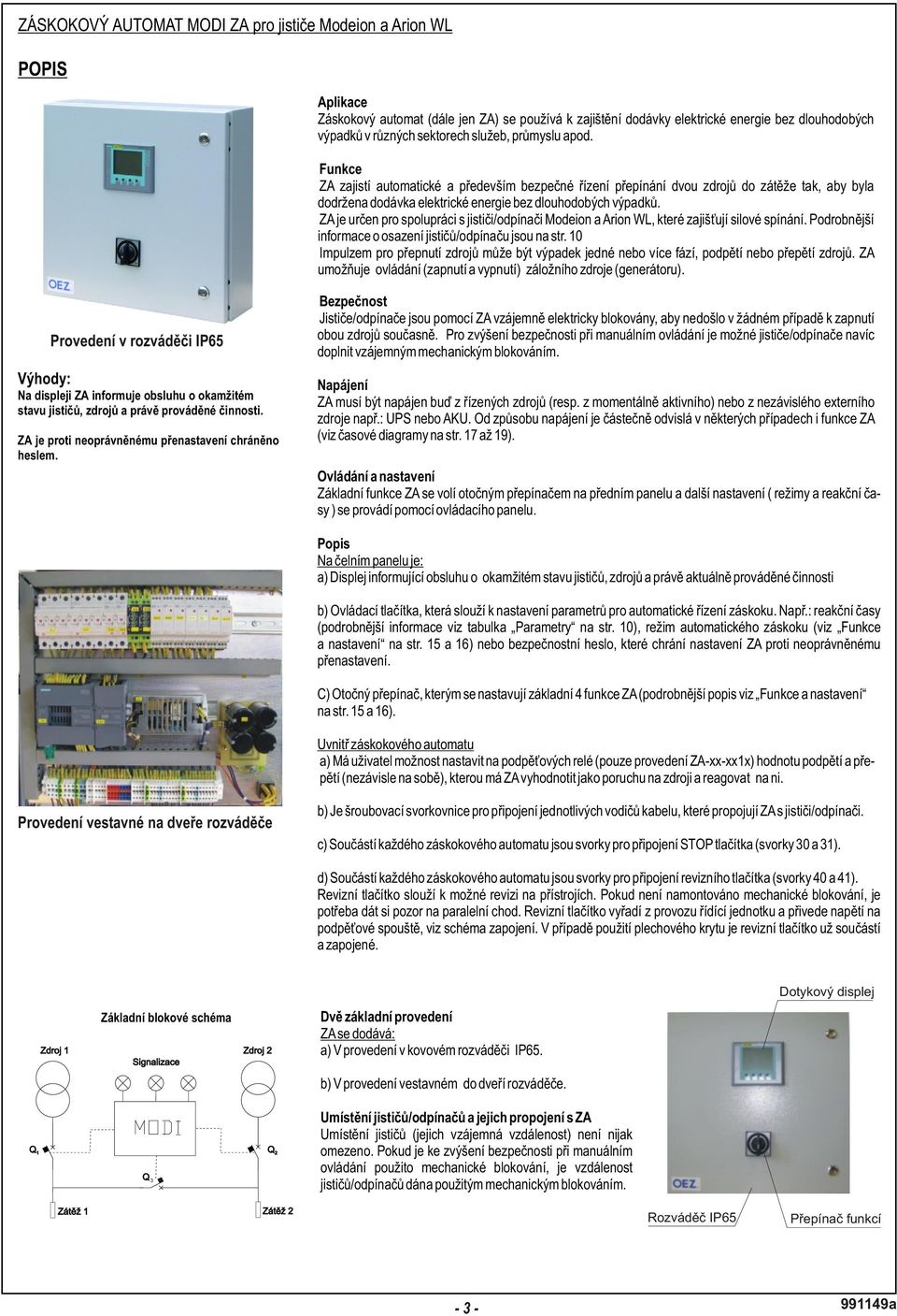
25 AUTOMATIC STANDBY UNIT MODI ZA for the circuit breakers Modeion and Arion WL DESCRIPTION Application The automatic standby unit (hereinafter referred to as ZA) is used to provide power supply without any longterm blackouts in various sectors of services, industry, etc. Function The automatic standby unit ensures automatic and, above all, safe control of switching of two power supplies to two loads sothat the electric poweris supplied without longfailures. The automatic standby unit is designed for collaboration with circuit breakers/switch-disconnectors Modeion and Arion WL, which ensure power switching. For detailed information on circuit breaker/switch-disconnector fitting see page 10. The power supplies can be switched over by a failure of one or more phases, undervoltage or overvoltage of the power supplies. The automatic standby unit enables the control (switching on/off) of the backuppowersupply (generator). Design in switchboard IP65 Advantages: The display of the automatic standby unit informs the operator of the immediate state of circuit breakers, power supplies and actually performed action. The automatic standby unit is protected against unauthorized resetting by the password. Safety The circuit breakers/switch-disconnectors are electrically interlocked by means of the automatic standby unit so that in no case both the power supplies can be switched on simultaneously. To increase safety in manual control it is possible to complete the circuit breakers/switch-disconnectors by mechanical interlocking. Power supply The automatic standby unit must be supplied either from controlled power supplies (or from a momentarily active one) or from an independent external power supply such as UPS or AKU. The function of the automatic standby unit depends in some cases on the power supply Metod (see time diagrams on page 17-19). Control and setting Basic functions of the automatic standby unit are selected by a rotary switch on the front panel, and additional settings (modes and reaction times) are set by means of control panel. Description On the front panel there is: a)adisplay informing the operator about immediate state of circuit breakers, power supplies and actually performed action. b)touch display for setting the parameters for automatic control of the standby mode. Example: reaction times (for detailed information see Table of Specifications on page 10), automatic standby mode (see functions and setting on page 15-16) or security password, which protects the automatic standby unit against unauthorized resetting. c)rotary switch for setting of 4 basic functions of the automatic standby unit(for detailed description see "functions and setting" on page 15 and 16). The built-in design on the switchboard door In the automatic standby unit: a)the user can use undervoltage relays (only for design ZA-xx-xx1x) to set the values of undervoltage or overvoltage (independently of each other) to be evaluated by the automatic standby unit as a power supply failure with taking an appropriate action. b)there is a screw terminal block for connection of individual conductors, which connect the automatic unit with circuit breakers/switch-disconnectors. c) Every automatic standby unit includes terminals for connection of the STOPbutton (terminals 30 and 31). Basic block diagram d) Every automatic standby unit includes terminals for connection of the inspection button (terminals 40 and 41). The inspection button serves for possible checks on instruments. If no mechanical interlocking is installed, it is necessary to beware of a parallel run. The inspection button will disable the control unit operation and will supply power to the under-voltage releases, see the wiring diagram. If the sheet-steel cover is used, the inspection button is already included and is connected. Touch display Two basic designs Automatic standby unit is delivered: a) In metallic switchboard design IP65. b)i n built-in design in the switchboard door. 3 The arrangement of circuit breakers/switch-disconnectors and their connection to the automatic standby unit The arrangement of circuit breakers (a distance between them) is not limited in any way. If mechanical interlocking is used to increase safety in manual control, the distance between the circuit breakers/switch-disconnectors is given by the used mechanical interlocking. Switchboard IP65 Functions switch a
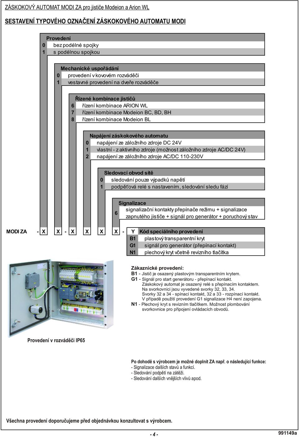
26 AUTOMATIC STANDBY UNIT MODI ZA for the circuit breakers Modeion and Arion WL COMPOSITION OF TYPE DESIGNATION 0 1 Design for control of two power supplies with longitudinal coupling with longitudinal coupling 0 1 Mechanical arrangement built-in design on the switchboard door metallic switchboard design Controlled combinations of circuit breakers control of combination of ARION WL control of combination of Modeion BC, BD, BH control of combination of Modeion BL Power supply of the automatic standby unit power supply of the backup power supply DC 24V own from active power supply (optional backup power supply AC/DC 24V power supply of the backup power supply AC/DC V Network monitoring circuit 0 monitoring of only loss of voltage 1 undervoltage relays with setting, monitoring of phase sequence 6 Signalling signal contacts of mode switch + signalling of circuit breaker switched ON + signal for the generátor + failure state MODI ZA - X X - X X X X - Y Special design code B1 plastic transparent cov er G1 signal for the generator (make-and-break contact) N1 sheet-steel cover, including the inspection button Customised design: B1 - The circuit breaker is fitted with a plastic transparent cover. G1 - Signal for the generator start - make-and-break contact. The automatic standby unit is fitted with a relay with a make-andbreak contact. Terminals 32, 33, 34 are conducted to the terminal b lock. Terminals 32 and 34 - make contact, 32 and 33 - break contact. In the case of use of the G1design, the H4 signalling is not connected. N1 - Sheet-steel cover with an inspection button. Possibility of sealing Of the terminal block for connection of the control circuits. Design in switchboard IP65 By agreement with the manufacturer, it is possible to complete the automatic standby unit e.g. by the following functions: - S ignalling of further states and functions. - M onitoring of undervoltage on the load. -Monitoring of other external influences etc. We recommend consulting all designs with the manufacturer before placing an order a a
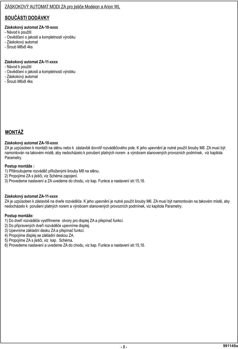
27 AUTOMATIC STANDBY UNIT MODI ZA for the circuit breakers Modeion and Arion WL PARTS OF SUPPLY Automatic standby unit ZA-10-xxxx - Instruction for use -Certificate of product quality and completeness -Automatic standby unit -Screw M8x8 4 pcs Automatic standby unit ZA-11-xxxx -Instruction for use -Certificate of product quality and completeness -Automatic standby unit - Screw M6x8 4 pcs INSTALLATION Automatic standby unit ZA-10-xxxx The switchboard of the automatic standby unit is adapted for the installation on the wall or integration in a distribution panel. It is necessary to use M8 screws to fasten it. The automatic standby unit mustbemountedin such placethat validstandards and operating conditions statedby themanufacturer, see the chapter Parameters, areobserved. I nstallation procedure: 1)Fasten the switchboard on the wall by means of the attached screws M8. 2)Interconnect the automatic standby unit with the circuit breakers, see Wiring diagram. 3)Perform setting and 5put 6the automatic standby unit into operation, see the chapter Functions and setting page 1, 1. Automatic standby unit ZA-11-xxxx The automatic standby unit is adapted for the mounting on the switchboard door. It is necessary to use M6 screws to fasten it. The automatic standby unit must be mounted in such place that valid standards and operating conditions stated by the manufacturer, see the chapter Parameters, are observed. Installation procedure: 1)Cut openings for the automatic standby unit display and function switch in the switchboard door. 2) Fasten the display in the prepared switchboard door. 3)Fasten the base plate of the automatic standby unit and the function switch. 4)Interconnect the display with the automatic standby unit base plate. 5)Interconnect the automatic standby unit with the circuit breakers, see chap. Wiring diagram. 6)Perform setting and 5put 6the automatic standby unit into operation, see the chapter Functions and setting page 1, a
28 AUTOMATIC STANDBY UNIT MODI ZA for the circuit breakers Modeion and Arion WL DIMENSIONS Design ZA-x0-xxx Drilling diagram for wall 32, , a
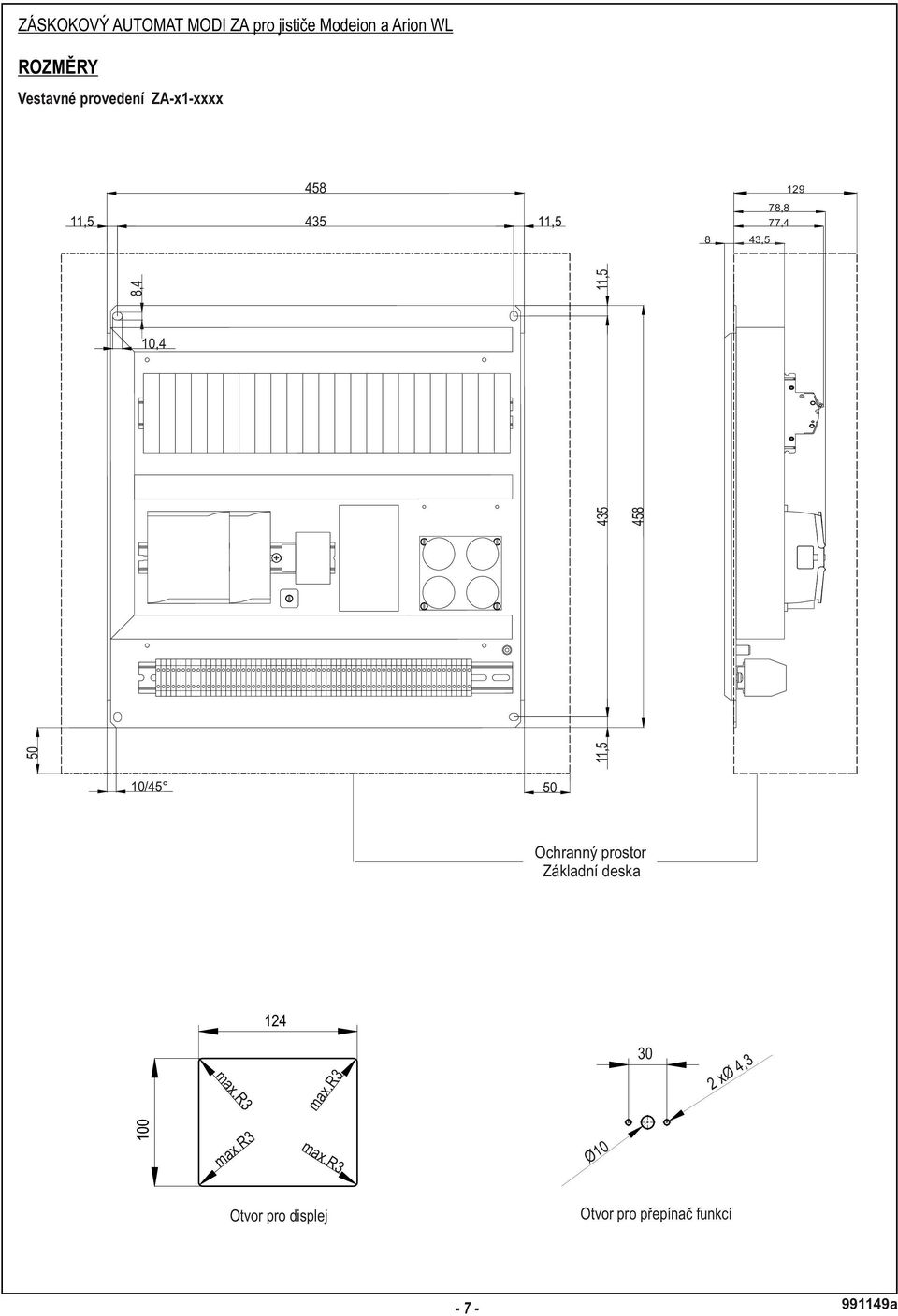
29 AUTOMATIC STANDBY UNIT MODI ZA for the circuit breakers Modeion and Arion WL DIMENSIONS Design ZA-x1-xxxx , , ,8 77,4 43,5 10,4 10/45 50 Protective space Base plate 30 Opening for display Opening for functions switch a
30 AUTOMATIC STANDBY UNIT MODI ZA for the circuit breakers Modeion and Arion WL DIMENSIONS Built-in design with ZA-x1-xxxx-B1 plastic cover , , ,4 10/45 50 Drilling diagram for mounting plastic cover a a
31 ZÁSKOKOVÝ AUTOMAT MODI ZA pro jistie Modeion a Arion WL ROZMRY Vestavné provedení s plechovým krytem ZA-x1-xxxx-N , a
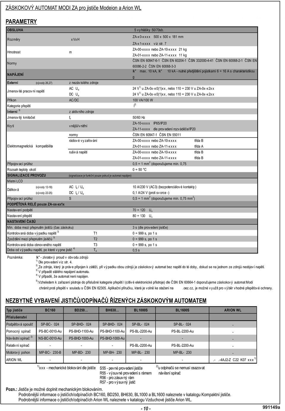
32 AUTOMATIC STANDBY UNIT MODI ZA for the circuit breakers Modeion and Arion WL SPECIFIKATIONS OPERATOR Dimensions Weight Standards POWER SUPPLY Ik" = max. 10 ka, Ik" = >10 ka - nutné pedjištní pojistkami 6 16 A s charakteristikou gg External (outlets 26,27) from independent power supply Rated operating voltage AC U e 24V 1) for ZA-1x -x 0(1)x x, or V for ZA-0x -x 2x x DC U e 24V 1) for ZA-1x -x 0(1)x x, or V for ZA-0x -x 2x x Input pow er AC/DC 100 VA / 100 W Ov erv oltage category I 2) Internal 3) from activ e power supply Rated frequency Degree of protection f n internal/ex ternal 50/60 Hz ZA-0x-xxxx IP65/IP20 ZA-x1-xxxx by design switchboard/ip20 standards EN , EN radio emission ZA-00-xxxx or ZA-10-xxxx classb Electromagnetic compatibility ZA-01-xxxx or ZA-11-xxxx classa disturbing v oltages ZA-00-xxxx or ZA-10-xxxx class B ZA-01-xxxx or ZA-11-xxxx classb Connecting cross-section Range of ambient temperature 0,5 1 mm 2 (recommended section min. 0,75 mm 2 ) 0 50 C OPERATION SIGNALLING Local LCD Remote (outlets 12-15) (outlets 22-25) Connecting cross-section UNDERVOLTAGE RELAYS Undervoltage setting Ov erv oltage setting WxHxD TIME SETTING Min. time between circuit breaker switching (standby time) Controlled time of loss of voltage 4) T1 Min. time betw een circuit breaker sw itching 4) T2 Controlled time of voltage renewal Time from loss of voltage to circuit breaker action 5) m (the signalling only functions if the automatic standby unit is supplied) AC I e /U e 10 A/230 V (AC-3) (potential-less contacts) DC I e /U e 0,1 A/24 V (against terminal ) S 0,5 1 mm 2 (recommended section min. 0,75 mm 2 ) T s,by1s T A 0,5s person w ith relev ant electrotechnical qualification ZA-10-x x x x 500 x 500 x 181 mm ZA-11-xxxx see page 7 ZA-10-xxxx nebo ZA-10-xx xx 21 kg ZA-11-xxxx nebo ZA-11-xx xx 11 kg SN EN ; SN EN ; SN ; SN EN ; SN EN ; SN EN % U n % U n 3 s (according to circuit breaker design) 0 999s,by1s 0 999s,by1s Note: 1) Ik - short-circuit current in the circuit of power supplies 2) Depending on design, see page 4. From the power supply which is connected to the load; in failure of both power supplies the automatic standby unit is without voltage until voltage is renewed on one of 5) the power supplies. 4) In case of permanent supplying of the automatic standby unit. 5) In case that the automatic standby unit is not supplied. With regard to classification of the device in the overvoltage category I (sensitive electronic devices) according to SN EN it is recommended to protect the automatic standby unit MODI against overvoltage in accordance with EN For selection of an appropriate overvoltage protection it is possible to refer to the Overvoltage protections application manual, which can be freely downloaded at NECESSARY EQUIPMENT OF CIRCUIT BREAKERS/SWITCH-DISCONNECTORS CONTROLLED BY THE AUTOMATIC STANDBY UNIT Circuit breaker type BC160 BD250 BH630 BL1000S BL1600S ARION WL Accessories Underv oltage release SP-BC-X024 SP-BHD-X024 SP-BHD-X024 SP-BL-X024 SP-BL-X024 - Aux iliary sw itch PS-BC-0010-Au PS-BHD-1100-Au PS-BHD-1100-Au PS-BL-2200-Au PS-BL-2200-Au - 2) Alarm switch NS-BC-0010-Au PS-BHD-1000-Au PS-BHD-1000-Au Relativ e sw itch PS-BL-2200-Au PS-BL-2200-Au - Motor driv e MP-BC-X230-B MP-BD-X230 MP-BH-X230 MP-BL-X230 MP-BL-X230 - ARION WL AJ2-Z+C22+K07+x x x 1) 1) xxx - mechanicalinterlocking according to circuit breaker S55 - fixed design R55 - withdrawable design with frame R56 - for plug-in frame 2) for switch-disconnectors it is not necessary to install a signal switch R57 - withdrawable circuit breaker Note: Circuit breakers can be fitted by the mechanical interlocking. For detailed information on circuit breakers/switch-disconnectors BC160, BD250, BH630, BL1000 and BL1600 see the catalogue Moulded case circuit breakers. For detailed information on circuit breakers/switch-disconnectors Arion WL see the catalogue Air circuit breakers Arion WL a
33 AUTOMATIC STANDBY UNIT MODI ZA for the circuit breakers Modeion and Arion WL WIRING DIAGRAM Connectingí for Bc L+ N- N- N- N- N- N- SB1 H1 H2 H3 H4 H5 H6 H7 H8 H9 H10 T1 L3 L2 L1 N PE F 1L1 1L2 1L3 N PE SA 18 XT0 L+ N Uz Uv 2L1 2L2 2L3 N PE F T2 L1 L2 L3 N PE 1.BC BC ZA BC BC SP-BC-X SP-BC-X MP-BC-X230-B MP-BC-X230-B SA2 3.BC D2 D1 SP-BC-X024 3.PS-BC-0010-Au BC MP-BC-X230-B L1 L2 L3 N PE Z1 1.NS-BC-0010-Au L1 L2 L3 N PE Z2 T G F - transformer - phase sequence must be observed - generator - phase sequence must be observed - fuses 6-16A with characteristic gg Setting of the mode of the motor drive control 0 N ZA - automatic standby unit XT0 - connecting terminal block SA - function switch H1-6 - function signalling of automatic standby unit H7 - circuit breaker 1 switched ON signal H8 - circuit breaker 2 switched ON signal H9 - circuit breaker 3 switched ON signal (coupling) H10 - error signal 26(L+), 27(N-) - external supplying from independent power supply SB1 - stop button (only design ZA-xx-xxxx-A3) A/AC 230 V (AC-3) - 0,1 A/DC 24 V (against terminal / - / minus ) - 0,1 A/DC 24 V (against terminal / - / minus ) - 0,1 A/DC 24 V (against terminal / - / minus ) - 0,1 A/DC 24 V (against terminal / - / minus ) - AC/DC 24 V for ZA-xx-x0xx and ZA-xx-x1xx, or AC/DC 110 V, AC 230 V / DC 220 V for ZA-xx-x2xx 1.BC160 - circuit breaker of power supply 1 SP-BC-X024 3.PS-BC-0010-Au 1.NS-BC-0010-Au MP-BC-X230-B 2.BC160 - circuit breaker of power supply 2 SP-BC-X024 3.PS-BC-0010-Au 1.NS-BC-0010-Au MP-BC-X230-B 3.BC160 - circuit breaker of the coupling SP-BC-X024 3.PS-BC-0010-Au 1.NS-BC-0010-Au MP-BC-X230-B - undervoltage release - auxiliary switch - alarm switch - motor drive - undervoltage release - auxiliary switch - alarm switch - motor drive - undervoltage release - auxiliary switch - alarm switch - motor drive Z - load Note: during the use of the switch-disconnector it is not necessary to use the signal switch. In the case that the signal switch is not installed, it is necessary to interconnect terminals for connection of the switch(1st source - terminals 1 and 2; 2nd source - terminals 101 and 102) a
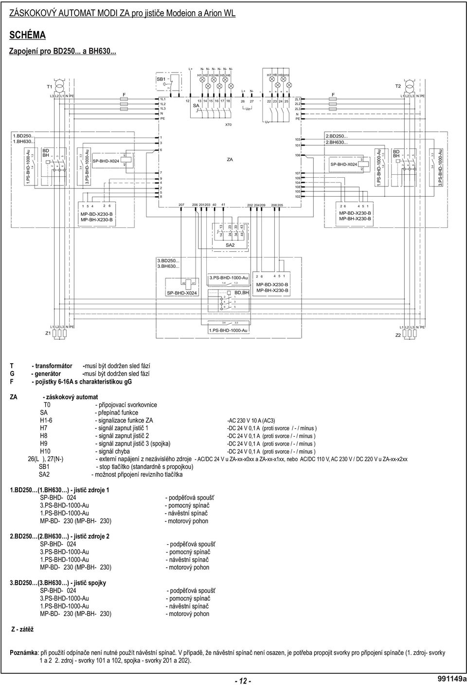
34 AUTOMATIC STANDBY UNIT MODI ZA for the circuit breakers Modeion and Arion WL WIRING DIAGRAM Connecting for BD and BH L+ N- N- N- N- N- N- T1 L3 L2 L1 N PE F SB1 1L1 1L2 1L3 12 H1 H2 H3 H4 H5 H SA L+ N Uz - - H7 H8 H9 H L1 2L2 2L3 F T2 L1 L2 L3 N PE N PE XT0 Uv N PE 1.BD BH BD BH SP-BHD-X ZA BD BH SP-BHD-X024 BD BH MP-BD-X230-B MP-BH-X230-B MP-BD-X230-B MP-BH-X230-B SA2 3.BD BH A2 A1 SP-BHD-X024 3.PS-BHD-1000-Au BD,BH MP-BD-X230-B MP-BH-X230-B L1 L2 L3 N PE Z1 1.PS-BHD-1000-Au Z2 L1L2L3 N PE T G F - transformer - phase sequence must be observed - generator - phase sequence must be observed - fuses 6-16A with characteristic gg ZA - automatic standby unit XT0 - connecting terminal block SA - function switch H1-6 - function signalling of automatic standby unit H7 - circuit breaker 1 switched ON signal H8 - circuit breaker 2 switched ON signal H9 - circuit breaker 3 switched ON signa (coupling)l H10 - error signal 26(L+), 27(N-) - external supplying from independent power supply SB1 - stop button (only design ZA-xx-xxxx-A3) - 10 A/AC 230 V (AC-3) - 0,1 A/DC 24 V (against terminal / - / minus ) - 0,1 A/DC 24 V (against terminal / - / minus ) - 0,1 A/DC 24 V (against terminal / - / minus ) - 0,1 A/DC 24 V (against terminal / - / minus ) - AC/DC 24 V for ZA-xx-x0xx and ZA-xx-x1xx, or AC/DC 110 V, AC 230 V / DC 220 V for ZA-xx-x2xx 1.BD250 (1.BH630 ) - circuit breaker of power supply 1 SP-BHD-X024 - undervoltage release 3.PS-BHD-1000-Au - auxiliary switch 1.PS-BHD-1000-Au - alarm switch MP-BD-X230 (MP-BH-X230) - motor drive 2.BD250 (2.BH630 ) - circuit breaker of power supply 2 SP-BHD-X024 - undervoltage release 3.PS-BHD-1000-Au - auxiliary switch 1.PS-BHD-1000-Au - alarm switch MP-BD-X230 (MP-BH-X230) - motor drive 3.BD250 (3.BH630 ) - circuit breaker of the coupling SP-BHD-X024 - undervoltage release 3.PS-BHD-1000-Au - auxiliary switch 1.PS-BHD-1000-Au - alarm switch MP-BD-X230 (MP-BH-X230) - motor drive Z - load Note: during the use of the switch-disconnector it is not necessary to use the signal switch. In the case that the signal switch is not installed, it is necessary to interconnect terminals for connection of the switch(1st source - terminals 1 and 2; 2nd source - terminals 101 and 102) a
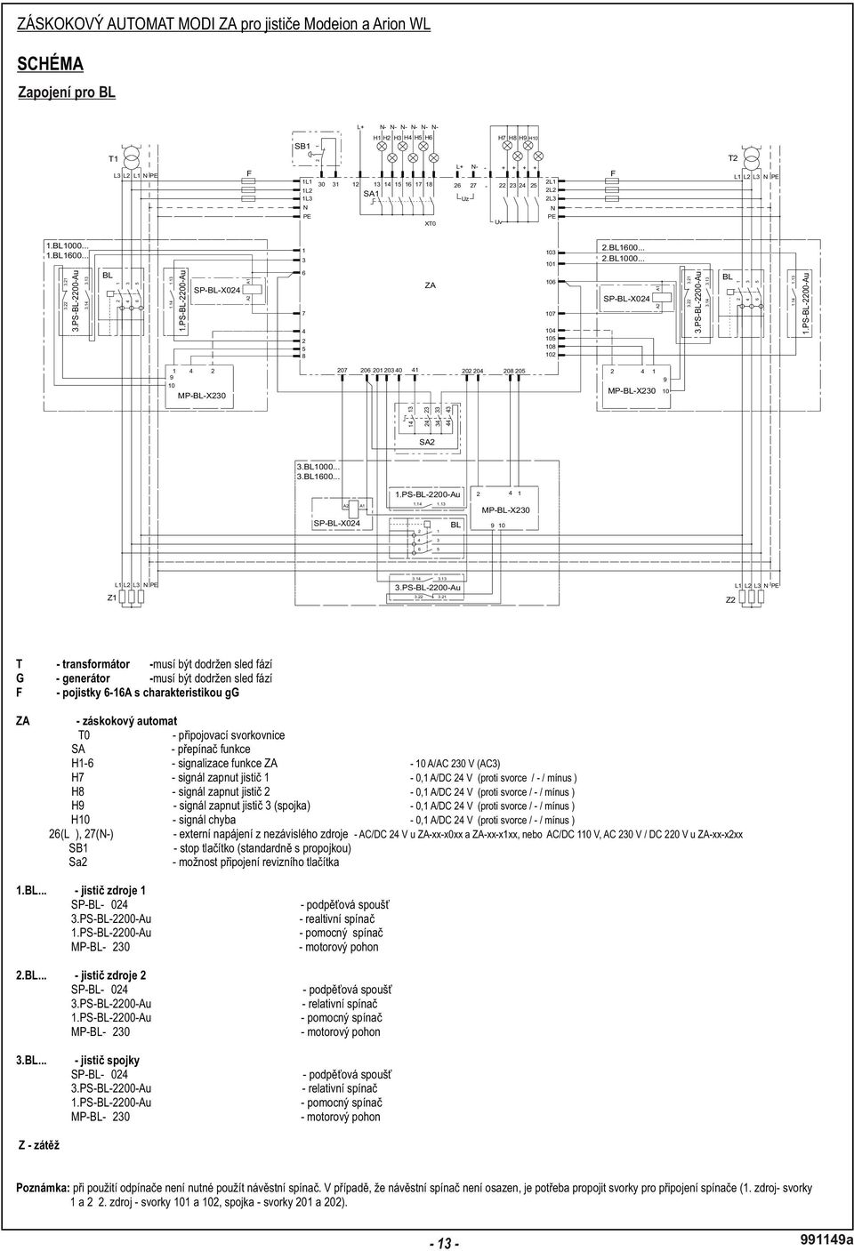
35 AUTOMATIC STANDBY UNIT MODI ZA for the circuit breakers Modeion and Arion WL WIRING DIAGRAM Connecting for BL L+ N- N- N- N- N- N- T1 L3 L2 L1 N PE F SB1 1L L2 1L3 H1 H2 H3 H4 H5 H SA1 L+ N Uz H7 H8 H9 H L1 2L2 2L3 F T2 L1 L2 L3 N PE N N PE XT0 Uv PE 1.BL BL BL BL BL SP-BL-X024 6 ZA 106 SP-BL-X024 BL MP-BL-X MP-BL-X SA2 3.BL BL A2 SP-BL-X024 A1 1.PS-BL-2200-Au BL MP-BL-X Z1 L1 L2 L3 N PE PS-BL-2200-Au Z2 L1 L2 L3 N PE T G F ZA - transformer - phase sequence must be observed - generator - phase sequence must be observed - fuses 6-16A with characteristic gg - automatic standby unit XT0 - connecting terminal block SA - function switch H1-6 - function signalling of automatic standby unit H7 - circuit breaker 1 switched ON signal H8 - circuit breaker 2 switched ON signal H9 - circuit breaker 3 switched ON signa (coupling)l H10 - error signal 26(L+), 27(N-) - external supplying from independent power supply SB1 - stop button (only design ZA-xx-xxxx-A3) - 10 A/AC 230 V (AC-3) - 0,1 A/DC 24 V (against terminal / - / minus ) - 0,1 A/DC 24 V (against terminal / - / minus ) - 0,1 A/DC 24 V (against terminal / - / minus ) - 0,1 A/DC 24 V (against terminal / - / minus ) - AC/DC 24 V for ZA-xx-x0xx and ZA-xx-x1xx, or AC/DC 110 V, AC 230 V / DC 220 V for ZA-xx-x2xx 1.BL...- circuit breaker of power supply 1 SP-BL-X024 - undervoltage release 3.PS-BL-2200-Au - relative switch 1.PS-BL-2200-Au - auxiliary switch MP-BL-X230 - motor drive 2.BL...- circuit breaker of power supply 2 SP-BL-X024 3.PS-BL-2200-Au 1.PS-BL-2200-Au MP-BL-X230 3.BL...- circuit breaker of the coupling SP-BL-X024 3.PS-BL-2200-Au 1.PS-BL-2200-Au MP-BL-X230 - undervoltage release - relative switch - auxiliary switch - motor drive - undervoltage release - relative switch - auxiliary switch - motor drive Z - load Note: during the use of the switch-disconnector it is not necessary to use the signal switch. In the case that the signal switch is not installed, it is necessary to interconnect terminals for connection of the switch(1st source - terminals 1 and 2; 2nd source - terminals 101 and 102) a
36 AUTOMATIC STANDBY UNIT MODI ZA for the circuit breakers Modeion and Arion WL WIRING DIAGRAM Connecting for Arion WL L+ N- N- N- N- N- N- T1 L3 L2 L1 N PE F SB1 1L1 1L2 1L3 H1 H2 H3 H4 H5 H SA1 L+ N Uz - - H7H8H9H L1 2L2 2L3 F T2 L1 L2 L3 N PE N PE XT0 Uv N PE 1.Arion 2.Arion X5.2 X5.1 X6.7 X6.8 X5.12 X ZA X5.2 X5.1 X6.7 X6.8 X5.12 X5.11 X6.3 X6.4 X7.13 X6.5 X7.12 X X6.3 X6.4 X7.13 X6.5 X7.12 X SA2 3.Arion L1 L2 L3 N PE L1 L2 L3 N PE Z1 Z2 T G F ZA - transformer - phase sequence must be observed - generator - phase sequence must be observed - fuses 6-16A with characteristic gg automatic standby unit XT0 - connecting terminal block SA - function switch H1-6 - function signalling of automatic standby unit H7 - circuit breaker 1 switched ON signal H8 - circuit breaker 2 switched ON signal H9 - circuit breaker 3 switched ON signa (coupling)l H10 - error signal 26(L+), 27(N-) - external supplying from independent power supply SB1 - stop button (only design ZA-xx-xxxx-A3) - 10 A/AC 230 V (AC-3) - 0,1 A/DC 24 V (against terminal / - / minus ) - 0,1 A/DC 24 V (against terminal / - / minus ) - 0,1 A/DC 24 V (against terminal / - / minus ) - 0,1 A/DC 24 V (against terminal / - / minus ) - AC/DC 24 V for ZA-xx-x0xx and ZA-xx-x1xx, or AC/DC 110 V, AC 230 V / DC 220 V for ZA-xx-x2xx 1. Arion - circuit breaker of power supply 1 X5,6,7 - connector for connection of accessories (see the documentation of circuit breaker Arion) 2. Arion - circuit breaker of power supply 2 X5,6,7 - connector for connection of accessories (see the documentation of circuit breaker Arion) 2. Arion - circuit breaker of the coupling X5,6,7 - connector for connection of accessories (see the documentation of circuit breaker Arion) Z - load Note: if the switch-disconnector is used, it is not necessary to use the signal switch switched off by release. In the case that the switch is not installed, it is necessary to interconnect terminalsfor connection of the switch (1st source - terminals 1 and 2; 2nd source - terminals 101 and 102) a
37 AUTOMATIC STANDBY UNIT MODI ZA for the circuit breakers Modeion and Arion WL FUNCTION, SETTING Function: determines automatic or manual operation (It is set by the rotary switch) Mode: determines priority of power supplies in automatic operation (It is set by the control push-buttons of the automatic standby unit) Function: Function switch: 1) ) AUTOMATIC OPERATION, AUTOMATIC STANDBY (switch position 3, signalling H3) The automatic standby unit can work in three modes, which are selected by means of control push-buttons on the display. Possible setting: AA ) utomatic standby st b) Priority of 1 power supply nd cp ) riority of 2 power supply furthermore, it is possible to set min. time of switching between power supplies (T ), time for detection of voltage (T ) and power supply failure (T ). Mode: Position Function description 0 Circuit breakers off, system reset ( reset of error messages) 1 Circuit breaker 1 permanently on ( at mains failure the standby will not take place) 2 Circuit breaker 2 permanently on (at mains failure the standby will not take place) 3 Circuit breaker 1 and 3 permanently on - coupling (at mains failure the standby will not take place) 4 Circuit breaker 2 and 3 permanently on - coupling (at mains failure the standby will not take place) a) STANDBYFORBOTH POWERSUPPLIES Both loads can be supplied permanently from any power supply. In case of loss of voltage of the power supply the load is supplied from the load, the load is disconnected from the power supply and connected (via coupling closing) nd to 2 power supply. After voltage renewal of the original power supply the coupling opens, and the load is connected to the original power supply. 5 Circuit breaker 1 and 2 permanently on (at mains failure the standby will not take place) 6 Automatic operation, the circuit breakers are controled by the automatic standby unit ST b) STANDBYFOR1 POWERSUPPLY The load 1 can be supplied from the power supply 1 or the power supply 2, the load 2 can only be supplied from the power supply 2. In case of loss of voltage of the power supply 1, the load 1 is disconnected from the power supply 1, and connected to the power supply 2 (via coupling closing). After voltage renewal of the power supply 1 the coupling opens and the load 1 is connected to the original power supply. In loss of voltage of power supply 2 the load 2 will remain without voltage for the time of the loss of voltage of power supply 2, no standby will take place. 3 ND c) STANDBY FOR 2 POWER SUPPLY The load 2 can be supplied from the power supply 2 or the power supply 1, the load 1 can only be supplied from the power supply 1. In case of loss of voltage of the power supply 2, the load 2 is disconnected from the power supply 2, and connected to the power supply 1 (via coupling closing). After voltage renewal of the power supply 2 the coupling opens and the load 2 is connected to the original power supply. In loss of voltage of power supply 1 the load 1 will remain without voltage for the time of the loss of voltage of power supply 1, no standby will take place. st nd 2) MANUALOPERATION - both 1 power supply and 2 power supply are OFF (switchposition0) st 3) MANUALOPERATION - operation only with 1 power supply (switch position 1, signalling H1) st The load 1 is permanently supplied from 1 power supply. In case of lossof voltage, the power supply is disconnected from the load automatically. The power supply will 1) remain disconnected even after voltage renewal. The power supply can only be connected manually (by turning the switch gradually from position 1 to position 0-1). nd 4) MANUALOPERATION - operation only with 2 power supply ( switch position 2, signalling H2) nd The load 2 is permanently supplied from 2 power supply. In case of loss of voltage, the power supply is disconnected from the load automatically. The power supply will 1) remain disconnected even after voltage renewalthe power supply can only be connected manually (by turning the switch gradually from position 2 to position 0-2). st 5) MANUALOPERATION - operation only with 1 power supply with closed coupling ( switch position 3, signalling H3) Both loads are permanently supplied from 1st power supply. In case of loss of voltage,the power supply is disconnected from the load automatically. The power supply will 1) remain disconnected evenafter voltagerenewal. Thepower supply can only beconnected manually (by turning the switch gradually from position3 to position 0-3). nd 6) MANUALOPERATION - operation only with 2 power supply with closed coupling ( switch position 4, signalling H4) Both loads are permanently supplied from 2nd power supply. In case of loss of voltage, thepower supply is disconnectedfrom the load automatically. The power supply 1) will remain disconnected even after voltagerenewal.the power supply can only be connected manually (by turning the switchgradually from position 4 to position 0-4). 7) MANUALOPERATION -operation with both power supplies ( switch position 5, signalling H5) st nd The load 1 is permanently supplied from 1 power supply, The load 2 is permanently supplied from 2 power supply. In case of loss of voltage, the power supplies are disconnected from the loads automatically. The power supplies will remain disconnected even after voltage renewal. The power supplies can only be connected 1) Manually (by turning the switch gradually from position 5 to position 0-5). 1) in position 0 it is necessary to wait at least 2 s before further handling the switch a
38 AUTOMATIC STANDBY UNIT MODI ZA for the circuit breakers Modeion and Arion WL FUNCTION, SETTING Setting of undervoltage relays (o nly design ZA-xx-xx1x) The automatic standby unit monitors the level of voltage of power supplies, power failures and phase sequence by means of undervoltage relays. On these relays it is possible to set the overvoltage / undervoltage level, to which the automatic standby unit shall react within the range + 30 % / -20 %; in case of ensuring permanent power nd supply of the system from 2 or standby power supply, it is possible to set the tolerance of the monitored voltage at +/- 30 %. Delay of making of the undervoltage relay contact is set by the manufacturer and cannot be changed. Overvoltage setting st of 1 power supply Undervoltage setting st of 1 power supply Overvoltage setting nd of 2 power supply Undervoltage setting nd of 2 power supply Undervoltage relays Setting the contrast of display ZA After booting (time limit to automatic booting the main screen by default 3 seconds if I do not, the contrast can be set up when restarting ZA) select Control Panel OP Contrast UP nebo DOWN Setting of parameters All parameters are blocked by password. After entering the password, all parameter options are accessible until the parameter setup mode is terminated. The parameter setup menu is accessed by pressing the F1 key on the control panel. After it, it is necessary to enter the password again. The password consists of 4 digits. These are set on the keyboard that appears when clicking in the password box. The password must be confirmed by Enter. After it, press the key F1 Parameters to display the Parameter Setup menu. The password is the serial number of the automatic standby unit! Function mode of automatic standby unit ZA The required mode is set by pressing the relevant push-button in the Parameter menu (Main/backup, Equivalent, Backup/main). Current mode is displayed on the display. Control panel - main screen Time setting of automatic standby unit ZA 3 times are set in the parameter menu: T1 - The time, for which an error must sustain on the power supply to be considered a failure. T2 - The time, for which the load must be without voltage, i.e. the time of switching over between the circuit breakers. T3 - The time, in which the power supply must be renewed to be considered good. Termination of parameter setting Use the keys F2-4 for return to the main screen. Control panel - setting of parameters Connection to the ZA control unit Supply connection from ZA Earthing a
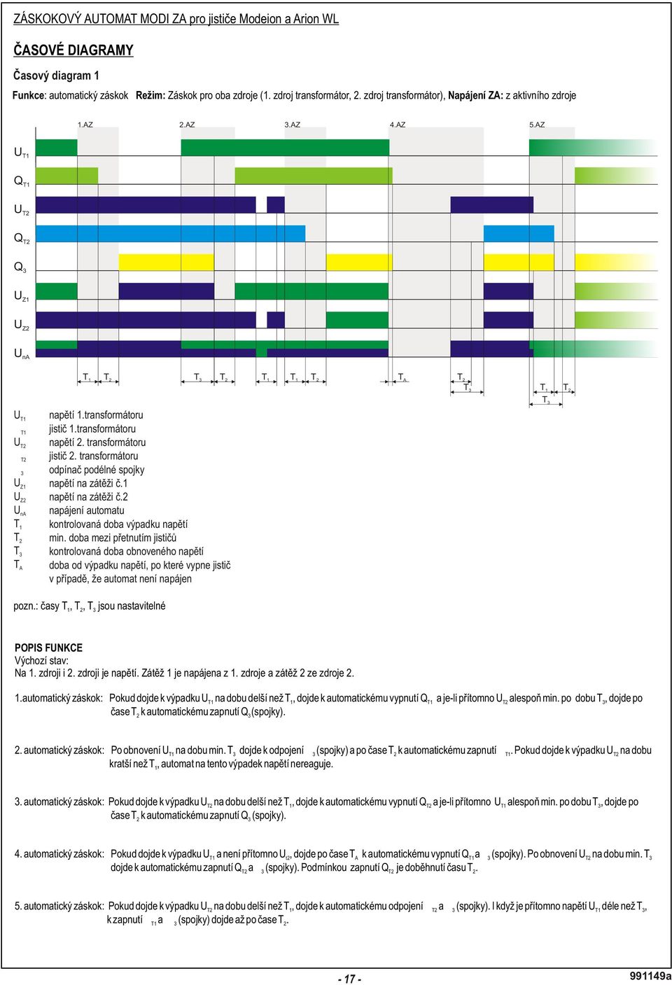
39 AUTOMATIC STANDBY UNIT MODI ZA for the circuit breakers Modeion and Arion WL TIME DIAGRAMS Time diagram 1 st nd Funcion: automatic standby Mode: Standby for both power supplies (1 power supply is a transformer, 2 power supply is a transformer) Power supply of the automatic standby unit: from active power supply 1.AZ 2.AZ 3.AZ 4.AZ 5.AZ U T1 Q T1 U T2 Q T2 Q 3 U Z1 U Z2 U na T 1 T 2 T 3 T 2 T 1 T 1 T 2 T A T 2 T 3 T 1 T 2 st UT1 voltage of 1 transformer st QT1 circuit breaker of 1 transformer nd UT2 voltage of 2 transformer nd QT2 circuit breaker of 2 transformer Q3 switch-disconnector of the longitudinal coupling UZ1 voltage on the load 1 UZ2 voltage on the load 2 UnA power supply of the automatic standby unit T1 controlled time of loss of voltage T2 min. time between circuit breaker switching T3 controlled time of voltage renewal TA time from loss of voltage to circuit breaker action in case that the automatic standby unit is not supplied T 3 note: times T 1, T 2, T3are adjustable FUNCTION DESCRIPTION Initial state: st nd st nd Voltage exists on both 1 power supply and 2 power supply. The load 1 is supplied from 1 power supply and the load 2 is supplied from 2 power supply. st 1 automatic sta ndby (1.AZ): In case of loss of UT1 for a time longer than T1, QT1 is switched off automatically and if UT2exists for at least T 3, Q 3(coupling) is switched on automatically aftert. 2 nd 2 automatic sta ndby (2.AZ): After renewal of UT1 for min. T 3, Q 3(coupling) is disconnected and QT1 is switched on automatically after T 2. In case of loss of UT2for a time shorter than T1, the automatic standby unit does not react to such loss of voltage. rd 3 automatic sta ndby (3.AZ): In case of loss of UT2 for a time longer thant 1, QT2is switched offautomatically and and if UT1exists for at least T 3, Q 3(coupling) is switched on automatically aftert. 2 th 4 automatic sta ndby (4.AZ): In case of loss of U and absence of U, Q and Q (coupling) are switched off automatically aftert.after renewal of U for min. T, Q and Q (coupling) are switched on automatically. The condition for switching Q on is expiration of time T. T1 T2 T1 3 A T2 3 t2 3 T2 2 th 5 automatic standby (5.AZ): In case of loss of UT2 for a time longer than T1, QT2 and Q 3 (coupling) are disconnected T1 automatically. Even if the voltage U is present Longer than T, the Q and Q (coupling) is switched on only after T. 3 T a
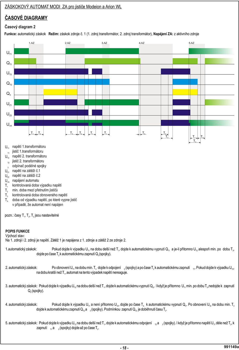
40 AUTOMATIC STANDBY UNIT MODI ZA for the circuit breakers Modeion and Arion WL TIME DIAGRAMS Time diagram 2 st nd Function: automatic standby Mode: standby for power supply No. 1 (1 power supply is a transformer, 2 power supply is a transformer) Power supply of the automatic standby unit: from active power supply 1.AZ 2.AZ 3.AZ 4.AZ 5.AZ U T1 Q T1 U T2 Q T2 Q 3 U Z1 U Z2 U na T 1 T 2 T 3 T 2 T 1 T 1 T A T 2 T 3 T 2 T 1 st UT1 voltage of 1 transformer st QT1 circuit breaker of 1 transformer nd UT2 voltage of 2 transformer nd QT2 circuit breaker of 2 transformer Q3 switch-disconnector of the longitudinal coupling UZ1 voltage on the load 1 UZ2 voltage on the load 2 UnA power supply of the automatic standby unit T1 controlled time of loss of voltage T2 min. time between circuit breaker switching T3 controlled time of voltage renewal TA time from loss of voltage to circuit breaker action in case that the automatic standby unit is not supplied note: times T 1, T 2, T3are adjustable T 3 FUNCTION DESCRIPTION I nitial state: st nd st nd Voltage exists on both 1 power supply and 2 power supply. The load 1 is supplied from 1 power supply and the load 2 is supplied from 2 power supply. st 1 automatic sta ndby (1.AZ): In case of loss of UT1 for a time longer than T 1, QT1 is switched off automatically and if UT2exists for at least T 3, Q 3(coupling) is switched on automatically after T 2. nd 3 2 automatic sta ndby (2.AZ): After renewal of UT1 for min. T, Q 3(coupling) is disconnected and QT1 is switched on automatically after T 2. In case of loss of UT2for a time shorter than T, the automatic standby unit does not react to such loss of voltage. rd 3 automatic sta ndby (3.AZ): In case of loss of UT2 for a time longer thant 1, QT2is switched offautomatically. Even if UT1is present at least for T 3, Q 3(coupling) will not switch on. th 4 automatic sta ndby (4.AZ): In case of loss of UT1 and absence of U T2, QT1is switched offautomatically after T A.After renewal of UT2 for min. T 3, QT2 and Q 3 (coupling) are switched on automatically. The condition for switching Q on is expiration of time T. th 5 automatic standby (5.AZ): 1 T2 2 In case of loss of UT2 for a time longer than T 1, QT2and Q 3(coupling) are disconnected T1 automatically. Even if the voltage U is present Longer than T, the Q and Q (coupling) is switched on only after T. 3 T a
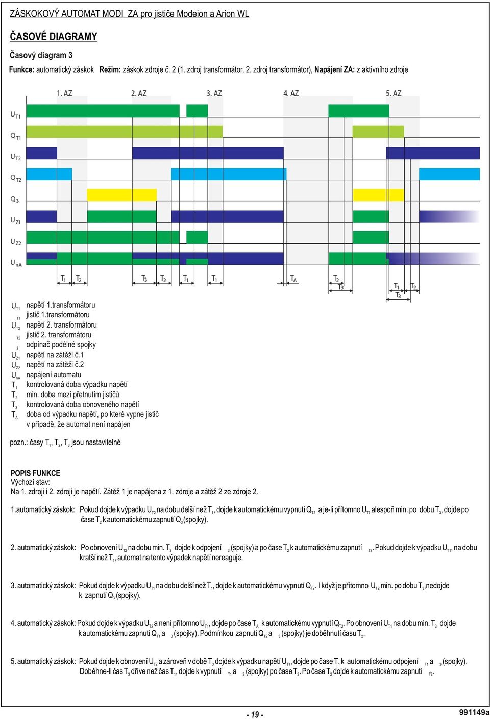
41 AUTOMATIC STANDBY UNIT MOD IZA for the circuit breakers Modeion and Arion WL TIME DIAGRAMS Time diagram 3 st nd Function: automatic standby Mode: standby for power supply No. 2 (1 power supply is a transformer, 2 power supply is a transformer) Power supply of the automatic standby unit: from active power supply st UT1 voltage of 1 transformer st QT1 circuit breaker of 1 transformer nd UT2 voltage of 2 transformer nd QT2 circuit breaker of 2 transformer Q3 switch-disconnector of the longitudinal coupling UZ1 voltage on the load 1 UZ2 voltage on the load 2 UnA power supply of the automatic standby unit T1 controlled time of loss of voltage T2 min. time between circuit breaker switching T3 controlled time of voltage renewal TA time from loss of voltage to circuit breaker action in case that the automatic standby unit is not supplied note: times T 1, T 2, T3are adjustable FUNCTION DESCRIPTION Initial state: st nd nd Voltage exists on both 1 power supply and 2 power supply.the load 1 is supplied from 1st power supply and the load 2 is supplied from 2 power supply st 1 automatic sta ndby (1.AZ): After renewal of UT2 for min. T 3, Q 3 (coupling) is disconnected and QT1is switched on automatically after T2In case of lossof UT1for a time shorter than T, the automatic standby unit does not react to such lossof voltage. 1 nd 2 automatic sta ndby (2.AZ): In case of loss of UT1 for a time longer than T 1, QT2 is switched off automatically. Even if UT2 is present at least for T 3, Q 3 (coupling) will not switch on. rd 3 automatic sta ndby (3.AZ): Pokud dojde k výpadku UT1na dobu delší než T 1, dojde k automatickému v ypnutí QT2. I když je pítomno UT 2min. po dobu T3,nedojde k z apnutí Q (spojky). 3 th 4 automatic sta ndby (4.AZ): In case of loss of UT2 and absence of U T1, QT2is switched offautomatically after T A.After renewal of UT1 for min. T 3, QT1 and Q 3 (coupling) are switched on automatically. The condition for switching Q and Q (coupling) on is expiration of time T. T2 3 2 th 5 automatic standby (5.AZ): In case of renewal of UT2 and loss of voltage of UT1in T 3, QT1 and Q 3 (coupling) 1 3 are disconnected automatically after T. IfT expires before T, Q and Q (coupling) are switched offaftert. Q is switched on automatically after T. 1 T1 3 3 T a
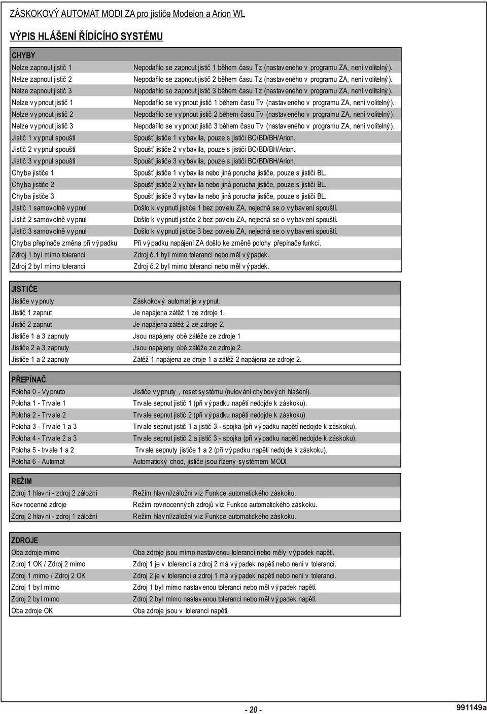
42 AUTOMATIC STANDBY UNIT MODI ZA for the circuit breakers Modeion and Arion WL ERROR MESSAGES ERRORS It is not possible to sw itch on the circuit breaker 1 It is not possible to sw itch on the circuit breaker 2 It is not possible to sw itch on the circuit breaker 3 It is not possible to sw itch off the circuit breaker 1 It is not possible to sw itch off the circuit breaker 2 It is not possible to sw itch off the circuit breaker 3 Circuit breaker 1 sw itched off by release Circuit breaker 2 sw itched off by release Circuit breaker 3 sw itched off by release Error of circuit breaker 1 Error of circuit breaker 2 Error of circuit breaker 3 Crcuit breaker 1 sw itched off spontaneously Circuit breaker 2 sw itched off spontaneously Circuit breaker 3 sw itched off spontaneously Error of sw itch change during outage Pow er supply 1 w as bey ond tolerance Pow er supply 1 w as bey ond tolerance Circuit breaker 1 w as not sw itched on in time Tz (set in the automatic standby unit program; not selectable) Circuit breaker 2 w as not sw itched on in time Tz (set in the automatic standby unit program; not selectable) Circuit breaker 3 w as not sw itched on in time Tz (set in the automatic standby unit program; not selectable) Circuit breaker 1 w as not sw itched on in time Tz (set in the automatic standby unit program; not selectable) Circuit breaker 2 w as not sw itched on in time Tz (set in the automatic standby unit program; not selectable) Circuit breaker 3 w as not sw itched on in time Tz (set in the automatic standby unit program; not selectable) The release of the circuit breaker 1 tripped (for BC160, BD250, BH630, Arion). If the circuit breaker is of w ithdraw able design, the message may be caused by w ithdraw al of the circuit breaker. The release of the circuit breaker 2 tripped (for BC160, BD250, BH630, Arion). If the circuit breaker is of w ithdraw able design, the message may be caused by w ithdraw al of the circuit breaker. The release of the circuit breaker 3 tripped (for BC160, BD250, BH630, Arion) The release of the circuit breaker 1 tripped or other fault of the circuit breaker (for BL1000, BL1600) The release of the circuit breaker 2 tripped or other fault of the circuit breaker (for BL1000, BL1600) The release of the circuit breaker 3 tripped or other fault of the circuit breaker (for BL1000, BL1600) Circuit breaker 1 sw itched off w ithout the automatic standby unit command; this is not tripping from a release Circuit breaker 2 sw itched off w ithout the automatic standby unit command; this is not tripping from a release Circuit breaker 3 sw itched off w ithout the automatic standby unit command; this is not tripping from a release In failure of pow er supply of the automatic standby unit, the position of the function sw itch w as changed Pow er supply 1 w as out of tolerance or had a failure Pow er supply 2 w as out of tolerance or had a failure CIRCUIT BREAKERS Circuit breakers off Automatic standby unit is sw itched off Circuit breaker 1 on Load 1 is supplied from pow er supply 1 Circuit breaker 2 on Load 2 is supplied from pow er supply 2 Circuit breakers 1 and 3 on Both loads are supplied from pow er supply 1 Circuit breakers 2 and 3 on Both loads are supplied from pow er supply 2 Circuit breakers 1 and 2 on The load 1 is supplied from the pow er supply 1 and the load 2 is supplied from the pow er supply 2. SWITCH Position0-switchedoff Circuit breakers off, sy stem reset (nulov ání chy bov ý ch hlášení ) Position 1 - permanently 1 Circuit breaker 1 permanently on (at mains failure the standby w ill not take place) Position 2 - permanently 2 Circuit breaker 2 permanently on (at mains failure the standby w ill not take place) Position 3 - permanently 1 and 3 Circuit breakers 1 and 3 permanently on - coupling (at mains failure the standby w ill not take place) Position 4 - permanently 2 and 3 Circuit breakers 2 and 3 permanently on - coupling (at mains failure the standby w ill not take place) Position 5 - permanently 1 and 2 Circuit breakers 1 and 2 permanently on (at mains failure the standby w ill not take place) Position 6 - automat Automatic operation, the circuit breakers are controled by the sy stem MODI MODE Pow er supply 1 main - pow er supply 2 backup Equiv alent pow er supplies Pow er supply 1 backup - pow er supply 2 main Main/backup mode, see Automatic standby function Equivalent pow er supplies mode, see Automatic standby function Main/backup mode, see Automatic standby function POWER SUPPLIES Both pow er supplies bey ond tolerance Pow er supply 1 OK / Pow er supply 2 not ready Pow er supply 1 not ready / Pow er supply 2 OK Pow er supply 1 w as out Pow er supply 2 w as out Both pow er supplies OK Both pow er supplies are out of the set tolerance or had a loss of v oltage Pow er supply 1 is w ithin tolerance and pow er supply 2 has loss of v oltage or is not w ithin tolerance Pow er supply 2 is w ithin tolerance and pow er supply 1 has loss of v oltage or is not w ithin tolerance Pow er supply 1 w as out of the set tolerance or had a loss of v oltage Pow er supply 2 w as out of the set tolerance or had a loss of v oltage Both pow er supplies are w ithin the v oltage tolerance a
43 AUTOMATIC STANDBY UNIT MODI ZA for the circuit breakers Modeion and Arion WL PUTTING INTO INTO OPERATION, TROUBLESHOOTING 1)P UTTING INTO INTO OPERATION: - Switch the SA function switch to position 0. - In case that the automatic standby unit is in the version with measurement of undervoltage / overvoltage and phase sequence (ZA-xx-xx1x), set the upper green trimmer on the measuring relays KA1, KA2 to basic value of +10 %, and the lower green trimmer to 10 %. - Switch on the both monitored power supplies; measure the voltage on the terminals 1L1-2L3 of the terminal block XT0 ; in case that the power supply outputs are led in four-conductor (3 phases + PEN), it is necessary to interconnect the terminals N and PE on the terminal block Xt0. - After application of voltage from the power supplies to the XT0 terminal board, the text "The circuit breakers off", "Both power supplies OK" appears on the display. - Check the parameter setting by means of the display of the control unit. SET BY THE MANUFACTURER: Mode - set to main/backup T1 - The time, for which an error must sustain on the power supply to be considered a failure - set to 0 s. T2 - The time, for which the load must be without voltage, i.e. the time of switching over between the circuit breakers - set to 0 s. T3 - The time, in which the power supply must be renewed to be considered good - set to 0 s. 2) FUNCTION TESTING - Switch the SA switch, hereinafter only SA to position 1 - permanently circuit breaker 1. st - The automatic standby unit must switch on the circuit breaker of 1 power supply and display the message " Circuit breaker 1 on ". - Switch the SA switch to position 0 off; the switched on circuit breaker must switch off; in this position it is necessary to be at least 2 s so that the control unit will not reset. - Switch the SA switch to position 2 - permanently circuit breaker 2. nd - The automatic standby unit must switch on the circuit breaker of 2 power supply and display the message Circuit breaker 2 on. - Switch the SA switch to position 0 off; the switched on circuit breaker must switch off; in this position it is necessary to be at least 2 s so that the control unit will not reset. - Gradually test in the same way the switch positions 1-5, the automatic standby unit must in individual positions switch the circuit breakers as stated in the chapter Functions and setting. - Switch the SA switch to position 6 - automatic operation. - The automatic standby unit must switch on the circuit breakers of the both power supplies and display the message " Circuit breakers 1 and 2 on" and " Both power supplies OK". s t - Switch off 1 power supply (it can be simulated by the switching off the circuit breaker FA1 on the panel of the automatic standby unit); the circuit breaker of 1 T1 power supply Q must switch off* and the circuit breaker of the coupling Q3 must switch on*. - On the display there must be the message " Circuit breakers 2 and 3 on" and " Power supply 1 not ready, Power supply 2 OK". st - Switch on 1 power supply (in case of simulation, switch on the circuit breaker FA1 on the panel of the automatic standby unit), the circuit breaker of the coupling st Q3 must switch off* and after T1 it the circuit breaker of 1 power supply Q must switch on*. - On the display there must be the message " Circuit breakers 1 and 2 on" and " Both power supplies OK. nd nd - Switch off 2 power supply (it can be simulated by the switching off the circuit breaker FA2 on the panel of the automatic standby unit); the circuit breaker of 2 power supply QT must switch off* and the circuit breaker of the2coupling Q must switch on. 3 - On the display there must be the message " Circuit breakers 1 and 3 on" and " Power supply 1 OK, Power supply 2 not ready". nd - Switch on 2 power supply (in case of simulation, switch on the circuit breaker FA2 on the panel of the automatic standby unit), the circuit breaker of the nd coupling Q3 must switch off* and after T2 it the circuit breaker of 2 power supply Q must switch on*. - On the display there must be the message " Circuit breakers 1 and 2 on" and " Both power supplies OK". - Switch the SA switch to position 0 off; the switched on circuit breakers must switch off; in this position it is necessary to be at least 2 s so that the control unit will not reset. * Time for power supply switching over i.e. the time from the moment of loss of voltage of the active power supply to the moment of switching on the standby is the sum of reaction times of the control unit, charging of circuit breaker and times present in the automatic standby unit menu a
44 AUTOMATIC STANDBY UNIT MODI ZA for the circuit breakers Modeion and Arion WL TECHNICAL SUPPORT OEZs.r.o. Šedivská Letohrad Czech Republic tel.: fax: Only materials which have low adverse environmental impact and which do not contain dangerous substances as specified in ROHS directive have been used in the product a
45
46
47
48
49
50
51
52
53
54
55
56
57
58
59
60
61
62
63
64
65
66
BD250NE305 BD250SE305
 ENGLISH ÈESKY INSTRUCTIONS OR USE, NÁVOD K POU ITÍ SWITCHING UNIT SPÍNACÍ BLOK BD5NE35 BD5SE35 BD5NE35 BD5SE35 OD-BHD-KS x CS-BD-A OD-BD-MS Installation, service and maintenance of the electrical equipment
 11.12. 100 ΕΙΣΟΔΟΣ = E / ENTRANCE = E = = 1174 550 ΤΥΠΟΠΟΙΗΜΕΝΟ ΚΥ = 2000 (ΕΠΙΛΟΓΗ: 2100) / CH STANDARD = 2000 (OPTIONAL: 2100) 243 50 ΚΥ/CH + 293 ΚΥ/CH +103 100 ΚΥ /CH 6 11 6 20 100 0,25 ΚΑ (CO) + 45
UPM3 Hybrid Návod na ovládání Čerpadlo UPM3 Hybrid 2-5 Instruction Manual UPM3 Hybrid Circulation Pump 6-9
 www.regulus.cz UPM3 Hybrid Návod na ovládání Čerpadlo UPM3 Hybrid 2-5 Instruction Manual UPM3 Hybrid Circulation Pump 6-9 CZ EN UPM3 Hybrid 1. Úvod V továrním nastavení čerpadla UPM3 Hybrid je profil PWM
20 ka / 1 s (dle typu cívky) přirozené
 přirozené") KATALOG CATALOGUE 051/03/2013 VÝKONOVÝ REAKTOR NN, NASTAVITELNÝ LOW VOLTAGE POWER REACTOR COIL, ADJUSTABLE pro napětí do 1000 V for voltages up to 1000V TYP LNN ISO 9001:2009 ISO 14001:2005 VŠEOBECNĚ Výkonový
KATALOG CATALOGUE 051/03/2013 VÝKONOVÝ REAKTOR NN, NASTAVITELNÝ LOW VOLTAGE POWER REACTOR COIL, ADJUSTABLE pro napětí do 1000 V for voltages up to 1000V TYP LNN ISO 9001:2009 ISO 14001:2005 VŠEOBECNĚ Výkonový
USER'S MANUAL FAN MOTOR DRIVER FMD-02
 USER'S MANUAL FAN MOTOR DRIVER FMD-02 IMPORTANT NOTE: Read this manual carefully before installing or operating your new air conditioning unit. Make sure to save this manual for future reference. FMD Module
Izolační manipulační tyče typ IMT IMT Type Insulated Handling Rod
 KATALOG CATALOGUE 024/09/2011 IZOLAČNÍ MANIPULAČNÍ TYČ INSULATED HANDLING ROD TYP IMT KOVOVÁ MANIPULAČNÍ TYČ METALLIC HANDLING ROD TYP KMT ISO 9001:2009 ISO 14001:2005 Izolační manipulační tyče typ IMT
obal manuálu, asi něco podobného jako u LC 100 asi by to chtělo lepší obrázek!!! FYTOSCOPE FS130 Instruction Guide
 obal manuálu, asi něco podobného jako u LC 100 asi by to chtělo lepší obrázek!!! FYTOSCOPE FS130 Instruction Guide možná tohle trochu zmenšit a dát sem i to varování LED RADIATION co je na další straně
2N LiftIP. IO Extender. Communicator for Lifts. Version
 2N LiftIP Communicator for Lifts IO Extender Version 2.4.0 www.2n.cz Description The IO extender helps you extend 2N LiftIP with 1 input and 2 outputs. The purpose of the input is to cancel the rescue
ADDRESS CONVERSION TABLE FOR MANUAL SETTING
 - (06-57) - ADDRESS CVERSI TABLE FOR MANUAL SETTING In the case of a multiple refrigerant system, each refrigerant system should be set an exclusive refrigerant. Conversion table of refrigerant and rotary
TechoLED H A N D B O O K
 TechoLED HANDBOOK Světelné panely TechoLED Úvod TechoLED LED světelné zdroje jsou moderním a perspektivním zdrojem světla se širokými možnostmi použití. Umožňují plnohodnotnou náhradu žárovek, zářivkových
2N Voice Alarm Station
 2N Voice Alarm Station 2N Lift1 Installation Manual Version 1.0.0 www.2n.cz EN Voice Alarm Station Description The 2N Voice Alarm Station extends the 2N Lift1/ 2N SingleTalk with an audio unit installed
SPECIFICATION FOR ALDER LED
 SPECIFICATION FOR ALDER LED MODEL:AS-D75xxyy-C2LZ-H1-E 1 / 13 Absolute Maximum Ratings (Ta = 25 C) Parameter Symbol Absolute maximum Rating Unit Peak Forward Current I FP 500 ma Forward Current(DC) IF
Mechanika Teplice, výrobní družstvo, závod Děčín TACHOGRAFY. Číslo Servisní Informace Mechanika: 5-2013
 Mechanika Teplice, výrobní družstvo, závod Děčín TACHOGRAFY Servisní Informace Datum vydání: 20.2.2013 Určeno pro : AMS, registrované subj.pro montáž st.měř. Na základě SI VDO č./datum: Není Mechanika
GUIDELINES FOR CONNECTION TO FTP SERVER TO TRANSFER PRINTING DATA
 GUIDELINES FOR CONNECTION TO FTP SERVER TO TRANSFER PRINTING DATA What is an FTP client and how to use it? FTP (File transport protocol) - A protocol used to transfer your printing data files to the MAFRAPRINT
PRO VNITŘNÍ MONTÁŽ TYP VF SULPHUR HEXAFLUORIDE CIRCUIT BREAKERS FOR INDOOR INSTALLATION TYPE VF
 VYPÍNAČE S PLYNEM SF 6 PRO VNITŘNÍ MONTÁŽ TYP VF SULPHUR HEXAFLUORIDE CIRCUIT BREAKERS FOR INDOOR INSTALLATION TYPE VF 7-38 kv, 800-2500 A, 16-40 ka ABB Power Distribution VŠEOBECNĚ Vypínaãe typové fiady
User manual SŘHV Online WEB interface for CUSTOMERS June 2017 version 14 VÍTKOVICE STEEL, a.s. vitkovicesteel.com
 1/ 11 User manual SŘHV Online WEB interface for CUSTOMERS June 2017 version 14 2/ 11 Contents 1. MINIMUM SYSTEM REQUIREMENTS... 3 2. SŘHV ON-LINE WEB INTERFACE... 4 3. LOGGING INTO SŘHV... 4 4. CONTRACT
UŽIVATELSKÁ PŘÍRUČKA
 UŽIVATELSKÁ PŘÍRUČKA Plni víry a naděje míříme kupředu. S odhodláním zlepšujeme své dovednosti. Zapomeňte na zklamání, ale nikoli na svůj nevyužitý potenciál. Touha překonat sám sebe a dosáhnout hranice
H2shop.cz. english česky
 návod Řídící elektronika HHO generátoru english česky Řídící jednotka slouží k uživatelskému nastavení impulzního proudu protékajícího HHO generátorem. Po nastavení jednotka sama udržuje konstantní nastavený
GENERAL INFORMATION RUČNÍ POHON MANUAL DRIVE MECHANISM
 KATALOG CATALOGUE RUČNÍ POHONY PRO VENKOVNÍ PŘÍSTROJE, MONTÁŽ NA BETONOVÉ SLOUPY MANUAL DRIVE MECHANISM FOR THE ACTUATION OF OUTDOOR TYPE SWITCHING DEVICES MOUNTED ON THE CONCRETE POLES TYP RPV ISO 9001:2009
topter AKTIVNÍ OCHRANA Leading Electrotechnology
 topter AKTIVNÍ OCHRANA Leading Electrotechnology topter Aktivní ochrana Průmyslové zásuvky IP44, IP66/IP67 P TECHNICKÉ PARAMETRY e shodě s normami EN 60309- IEC 60309- EN 60309-2 IEC 60309-2 EN 60529 IEC
DATA SHEET. BC516 PNP Darlington transistor. technický list DISCRETE SEMICONDUCTORS Apr 23. Product specification Supersedes data of 1997 Apr 16
 zákaznická linka: 840 50 60 70 DISCRETE SEMICONDUCTORS DATA SHEET book, halfpage M3D186 Supersedes data of 1997 Apr 16 1999 Apr 23 str 1 Dodavatel: GM electronic, spol. s r.o., Křižíkova 77, 186 00 Praha
KOVOVĚ KRYTÉ ROZVÁDĚČE S KOVOVÝMI PŘEPÁŽKAMI TYP SR 7,2-25 kv. METAL-CLAD SWITCHGEAR TYPE SR 7,2-25 kv
 KOVOVĚ KRYTÉ ROZVÁDĚČE S KOVOVÝMI PŘEPÁŽKAMI TYP SR 7,2-25 kv METAL-CLAD SWITCHGEAR TYPE SR 7,2-25 kv ROZVÁDĚČE TYPU SR SWITCHGEAR TYPE SR VŠEOBECNĚ GENERAL POUŽITÍ APPLICATION NORMY A PŘEDPISY STANDARDS
Compact power switches K 16 and K 32 J. Kompaktní výkonové spínače K 16 a K 32 J. Použití. Use > 96 <
 Použití K 16 J a K 32 J jsou 2-modulové třípólové vypínače jmenovitého proudu 16A a 32A se spínacím úhlem 90. Spínače mohou být upevněny na DIN lištu, nebo pomocí šroubů M4 na základovou desku. Rovněž
ZÓNOVÉ VENTILY S VRATNOU PRUŽINOU dvoucestné VZP 2XX 230 1P 001 třícestné VZP 3XX 230 1P 001
 Návod na instalaci a použití ZÓNOVÉ VENTILY S VRATNOU PRUŽINOU dvoucestné VZP 2XX 230 1P 001 třícestné VZP 3XX 230 1P 001 CZ verze 1.2 Popis: Zónové ventily s vratnou pružinou jsou určeny do hydraulických
Litosil - application
 Litosil - application The series of Litosil is primarily determined for cut polished floors. The cut polished floors are supplied by some specialized firms which are fitted with the appropriate technical
2N Helios Vario departure switch
 Description 2N Helios Vario departure switch Order no. 9135251E The purpose of this module is to extend the 2N Helios Vario door communicator with another switch, e.g., for switching the electric door
Modi. Záskokové automaty
 wwwoezcz OBSAH ZA POPIS SESTAVENÍ TYPOVÉHO OZNAČENÍ FUNKCE A REŽIMY ČASOVÉ DIAGRAMY PARAMETRY0 VYBAVENÍ JISTIČŮ0 TYPOVÉ OZNAČENÍ JISTIČE ARION WL URČENÍ MECHANICKÉHO BLOKOVÁNÍ JISTIČŮ MODEION SCHÉMA Zapojení
INDUCTION HEATING CAPACITORS KONDENZÁTORY PRO INDUKČNÍ OHŘEV
 INDUCTION HEATING CAPACITORS KONDENZÁTORY PRO INDUKČNÍ OHŘEV SCA - 2012-1 CONTENTS OBSAH 03 General technical information Obecné technické informace 04 Medium Frequency Capacitors - water cooled, up to
PC/104, PC/104-Plus. 196 ept GmbH I Tel. +49 (0) / I Fax +49 (0) / I I
 / I Fax +49 (0) / I I") E L E C T R O N I C C O N N E C T O R S 196 ept GmbH I Tel. +49 (0) 88 61 / 25 01 0 I Fax +49 (0) 88 61 / 55 07 I E-Mail sales@ept.de I www.ept.de Contents Introduction 198 Overview 199 The Standard 200
E L E C T R O N I C C O N N E C T O R S 196 ept GmbH I Tel. +49 (0) 88 61 / 25 01 0 I Fax +49 (0) 88 61 / 55 07 I E-Mail sales@ept.de I www.ept.de Contents Introduction 198 Overview 199 The Standard 200
USER'S MANUAL FAN MOTOR DRIVER FMD-01, FMD-03
 USER'S MANUAL FAN MOTOR DRIVER FMD-01, FMD-03 IMPORTANT NOTE: Read this manual carefully before installing or operating your new air conditioning unit. Make sure to save this manual for future reference.
harvia griffin COLOUR LIGHT Control unit Ridici jednotka
 harvia griffin COLOUR LIGHT Control unit Ridici jednotka 13082008 These instructions for installation and use are intended for owners of colour light units and control units and for electricians responsible
2N LiftIP. Voice Alarm Station. Communicator for Lifts. Version
 2N LiftIP Communicator for Lifts Voice Alarm Station Version 2.4.0 www.2n.cz Description The 2N Voice Alarm Station is a switch that helps you extend 2N LiftIP with one or more audio units installed on
Automatika na dávkování chemie automatic dosing
 Automatika na dávkování chemie automatic dosing Swimmingpool Technology Autodos 700 Automatické dávkování Autodos Autodos automatic dosing Autodos 700 je jedno-kanálové zaøízení, pro mìøení a dávkování.
Switch on the appropriate breaker and verify that the light is working properly.
 Package contents Name: MONA WALL PC970 wall light 445 Components included with unit: glass shade with light source, 1x metal light body, 1x wall mount, 3x terminal connectors, 2x hex screws M5, 1x hex
XCKN2121P20 pol.spín.xckn-čep a páka s plast.klad.1 najíž.směr horiz.- 1Z+1V-mžik.- M20
 Characteristics pol.spín.xckn-čep a páka s plast.klad.1 najíž.směr horiz.- 1Z+1V-mžik.- M20 Doplňky Ovládání spínače Elektrické připojení Tvar izol. kontaktu Nucené vypnutí Nucené vypnutí minimální silou
1-AYKY. Instalační kabely s Al jádrem. Standard TP-KK-133/01, PNE 347659-3. Konstrukce. Použití. Vlastnosti. Installation cables with Al conductor
 Instalační kabely s Al jádrem Installation cables with Al conductor Standard TP-KK-133/01, PNE 347659-3 4 3 2 1 Konstrukce Construction 1 Hliníkové jádro Aluminium conductor 2 Izolace PVC 3 Výplňový obal
ZB5AV013 bílá signální hlavice Ø22 plná čočka pro integ. LED
 Characteristics bílá signální hlavice Ø22 plná čočka pro integ. LED Doplňky CAD celková šířka CAD celková výška CAD celková hloubka Hmotnost přístroje Označení skříně Označení el. složení Prostředí Stupeň
SERVISNÍ MANUÁL PEGAS 250 E CEL OVO SERVICE MANUAL PEGAS 250 E CEL OVO
 MG136-1 PEGAS 250 E CEL OVO SERVICE MANUAL page 1 SERVISNÍ MANUÁL PEGAS 250 E CEL OVO SERVICE MANUAL PEGAS 250 E CEL OVO 1. VAROVÁNÍ WARNING UPOZORNĚNÍ Pouze osoba splňující kvalifikaci danou zákonem je
Hi-Res Audio/DNC Headset MDR-NC750
 Uživatelská příručka Hi-Res Audio/DNC Headset MDR-NC750 Obsah Začínáme...3 Úvod...3 Přehled... 3 Základy práce...4 Nošení náhlavní soupravy...4 Připojení náhlavní soupravy k vašemu zařízení... 4 Nastavení
NOVINKA. [Řada System 2] Dynamic Electronic Control
![NOVINKA. [Řada System 2] Dynamic Electronic Control](/thumbs/26/8859700.jpg "NOVINKA. [Řada System 2] Dynamic Electronic Control") MADE IN ITALY NOVÝ elektrický lineární hřebenový pohon s technologií DEC NEW Electrical linear rack actuator DEC technology: Technology DEC Dynamic Electronic Control Vyšší životnost pohonu a okna Automatické
MADE IN ITALY NOVÝ elektrický lineární hřebenový pohon s technologií DEC NEW Electrical linear rack actuator DEC technology: Technology DEC Dynamic Electronic Control Vyšší životnost pohonu a okna Automatické
Dvojitá lišta SASILplus 1000A pro připojení jednoho spotřebiče Double strip SASILplus for 1000A for connection of one consumer
 Dvojitá lišta SASILplus 1000A pro připojení jednoho spotřebiče Double strip SASILplus for 1000A for connection of one consumer Ve spínacích kombinacích rozvodů nn bývají často požadovány 3pólové vývody
Introduction to MS Dynamics NAV
 Introduction to MS Dynamics NAV (Item Charges) Ing.J.Skorkovský,CSc. MASARYK UNIVERSITY BRNO, Czech Republic Faculty of economics and business administration Department of corporate economy Item Charges
technický list TRANSIL TM 1.5KE6V8A/440A 1.5KE6V8CA/440CA www.gme.cz str 1
 Dodavatel: GM electronic, spol. s r.o., Křižíkova 77, 186 00 Praha 8 zákaznická linka: 840 50 60 70 technický list 1.5KE6V8A/440A 1.5KE6V8CA/440CA TRANSIL TM FEATURES PEAK PULSE POWER : 1500 W (10/1000µs)
Tento modul by bez problémů měl vyhovovat Vašemu zadání.
 Čítač kvalitní německé výroby IVO. Tento čítač je určen pro zabudování do panelu (držáku, popř. elektroinstalační krabice). Zástavbové rozměry x x mm (hloubka. mm vč. reset tlačítka). Tento čítač je vybaven
INSTALLATION MANUAL PD 0027.01
 INSTALLATION MANUAL PD 0027.01 OUTDOOR MOTOR DRIVE FOR MV DISCONNECTORS ISO 9001:2009 ISO 14001:2005 OHSAS 18001:2008 TYPE SUP a) STORAGE / SKLADOVÁNÍ The packed devices on wooden pallet it is not allowed
Použití. Application. Field of application. Rozsah použití A.1.1
 Uzavírací ventil V46.2 DN 10 50, PN 100 400 Regulační ventil V40.2 DN 10 50, PN 100 400 Globe valve V46.2 DN 10 50, PN 100 400 Control valve V40.2 DN 10 50, PN 100 400 Použití Uzavírací ventil (V 46.2)
Uživatelská příručka. USB Charger UCH20
 Uživatelská příručka USB Charger UCH20 Obsah Úvod...3 USB Charger popis... 3 Používání nabíječky USB... 4 Nabíjení zařízení... 4 Právní informace... 5 Declaration of Conformity...6 2 Úvod USB Charger popis
Návod na použití, montáž a údržbu Třícestný zónový kulový ventil s pohonem VZK 3xx - 230-1P - 001
 ávod na použití, montáž a údržbu Třícestný zónový kulový ventil s pohonem VZK 3xx - 230-1P - 001 CZ verze 1.0 1 POUŽITÍ Ventily s pohonem řady VZK 3xx - 230-1P mohou být použity ve spojení s jakýmkoliv
Pokyny k použití. Model-300. Napájecí zdroj. Návod na obsluhu Operating Instructions. se systémem Aquacontrol Napájací zdroj
 Pokyny k použití Model-300 Návod na obsluhu Operating Instructions Napájecí zdroj se systémem Napájací zdroj so systémom Power Supply with System BK 0011900 / PC AQUACONTROL Kryt aquacontrol Kryt aquacontrol
SGM. Smart Grid Management THE FUTURE FOR ENERGY-EFFICIENT SMART GRIDS
 WHO ARE WE? a company specializing in software applications for smart energy grids management and innovation a multidisciplinary team of experienced professionals from practice and from Czech technical
rozvodnice jednoduchá instalace spolehlivost reliability Swimmingpool Technology distribution boards simple installation
 rozvodnice distribution boards jednoduchá instalace simple installation spolehlivost reliability Swimmingpool Technology Transformátory Transformers Transformátor 100W - 100W transformer Trafo 100W v plastovém
Uživatelská příručka. Xperia P TV Dock DK21
 Uživatelská příručka Xperia P TV Dock DK21 Obsah Úvod...3 Přehled zadní strany stanice TV Dock...3 Začínáme...4 Správce LiveWare...4 Upgradování aplikace Správce LiveWare...4 Použití stanice TV Dock...5
BERGAMO FIRENZE RIMINI. Samozavírače a samozavírací závěsy Floor springs and hinges
 3 BERGAMO FIRENZE RIMINI Samozavírače a samozavírací závěsy Floor springs and hinges Bartosini s.r.o. Kancelář: Karvinská 1897, 737 01 Český Těšín tel.: +420 602 322 276; e-mail: bartosini@bartosini.cz
WL-5480USB. Quick Setup Guide
 Quick Setup Guide 1 Czech 7 Install Utility Software Note1: Before installing the utility software, DO NOT inserts the into your computer. If the adapter is inserted already, Windows will detect the adapter
:= = := :=.. := := := := ρ := := α := π α = α = := = :=
 := = := :=.. := := := := ρ := := α := π α = α = := = := := α := α := = := α := := α = = ρ ρ := := := = := = := := := + + := + + := + := := := := + + := + + := + = = = :=.. := η := η := := π = :=.. :=,
Ventil zpětný Z15.1 DN 10 50, PN 100 400 Piston check valve Z15.1 DN 10 50, PN 100 400
 DN 10 50, PN 100 400 DN 10 50, PN 100 400 Použití Zpětný ventil je samočinná armatura, zamezující zpětnému proudění provozní tekutiny, určená pro vodu, vodní páru, plyny i jiné provozní tekutiny používané
TECHNICKÝ LIST řada mechanických odvaděčů kondenzátu AUTODRAIN TECHNICAL DATA SHEET for mechanical autodrain equipment AUTODRAIN
 Popis: Nádoba s mechanickým plovákem k odstraňování pevných nečistot, vody, aerosolů, uhlovodíků, prachu oddělených separátory KING AIR se systémem stlačeného vzduchu. Rozdělení dle využití instalace:
Návod na použití, montáž a údržbu Třícestný kulový ventil s pohonem (s možností směšování) VZK-S 3xx - 230-2P - 001
 VZK-S 3xx - 230-2P - 001") ávod na použití, montáž a údržbu Třícestný kulový ventil s pohonem (s možností směšování) VZK-S 3xx - 230-2P - 001 CZ verze 1.0 1 POUŽITÍ Ventily s pohonem řady VZK-S 3xx - 230-2P mohou být použity ve
ávod na použití, montáž a údržbu Třícestný kulový ventil s pohonem (s možností směšování) VZK-S 3xx - 230-2P - 001 CZ verze 1.0 1 POUŽITÍ Ventily s pohonem řady VZK-S 3xx - 230-2P mohou být použity ve
2N Lift8 Audio unit cabin universal
 2N Lift8 Audio unit cabin universal Brief Manual Version 2.0.0 www.2n.cz EN The user does not come into direct contact with this product. The control and indication elements depend on the specific installation.
 If there is any inconsistency of weather forecast between Local Weather Station and this unit, the Local Weather Station's forecast should prevail. The trend pointer displayed on the LCD indicates the
Quick Start Guide. Clear. Rychlý průvodce nastavením
 CZ EN Quick Start Guide Clear Rychlý průvodce nastavením Measurement Měření Před Fully prvním charge použitím the blood plně pressure dobijte monitor baterii before přístroje. first use. 1 Rest your bare
Název společnosti: VPK, s.r.o. Vypracováno kým: Ing. Michal Troščak Telefon: Datum:
 Pozice Počet Popis 1 SCALA2 3-45 A Datum: 2.7.217 Výrobní č.: 98562862 Grundfos SCALA2 is a fully integrated, self-priming, compact waterworks for pressure boosting in domestic applications. SCALA2 incorporates
nkt instal CYKY 450/750 V Instalační kabely Standard PN-KV-061-00 Konstrukce Použití Vlastnosti Installation cables Construction
 Instalační kabely Installation cables Standard PN-KV-061-00 4 3 2 1 Konstrukce Construction 1 Měděná plná holá jádra Solid plain copper conductors 2 Izolace PVC 3 Výplňový obal 4 Plášť PVC PVC insulation
NAPÁJECÍ ZDROJE ČISTÝ VÝKON POWER SUPPLIES PURE POWER PROLUMIA
 ČISTÝ VÝKON PURE POWER NAPÁJECÍ ZDROJE POWER SUPPLIES LED napájecí zdroje Prolumia jsou k dispozici pro vnitřní i venkovní použití (vodotěsné). Díky tenkému provedení mohou být zdroje Prolumia snadno uloženy
Imunita tab.16, ČSN EN 61131-2 Odolnost vůči vibracím (sinusovým) Fc dle ČSN EN 60068-2-6
 Fc dle ČSN EN 60068-2-6") TECOMAT TC700 ZÁKLADNÍ DOKUMENTACE K MODULU BASIC DOCUMENTATION FOR MODULE PW-7906 2. vydání - září 2006 2 nd edition - September 2006 Podrobná uživatelská dokumentace je k dispozici v elektronické podobě
TECOMAT TC700 ZÁKLADNÍ DOKUMENTACE K MODULU BASIC DOCUMENTATION FOR MODULE PW-7906 2. vydání - září 2006 2 nd edition - September 2006 Podrobná uživatelská dokumentace je k dispozici v elektronické podobě
WI180C-PB. On-line datový list
 On-line datový list A B C D E F H I J K L M N O P Q R S T Technická data v detailu Technické údaje Řada příslušenství Upozornění Krytí Rozměry (Š x V x D) Popis Klasifikace Objednací informace Další provedení
TKGA3. Pera a klíny. Projekt "Podpora výuky v cizích jazycích na SPŠT"
 Projekt "Podpora výuky v cizích jazycích na SPŠT" Pera a klíny TKGA3 Tento projekt je spolufinancován Evropským sociálním fondem a státním rozpočtem ČR Pera a klíny Pera a klíny slouží k vytvoření rozbíratelného
INSTALAČNÍ NÁVOD OPERATING INSTRUCTION
 LED PRODISC II + LED PRODISC II MINI + LED PRODISC II MAXI INSTALAČNÍ NÁVOD OPERATING INSTRUCTION 4000944x 4000945x 4000940x 4000941x 4000946x 4000947x Prodisc II Mini Prodisc II Mini + MW senzor Prodisc
Připojení internetového modulu econet300 Do regulátoru ecomax 810P3-L TOUCH.
 Připojení internetového modulu econet300 Do regulátoru ecomax 810P3-L TOUCH. Connection of econet300 internet module to ecomax 810P3-L TOUCH Controller. Prosím ověřte verzi softwaru vašeho modulu ecomax.
3 Výplňový obal. 4 Plášť PE. Bedding
 Instalační kabely s Al jádrem Installation cables with Al conductor Standard VDE0276 T.603-5G-2 4 3 2 1 Konstrukce Construction 1 Hliníkové jádro Aluminium conductor 2 Izolace XLPE XLPE insulation 3 Výplňový
AIC ČESKÁ REPUBLIKA CZECH REPUBLIC
 ČESKÁ REPUBLIKA CZECH REPUBLIC ŘÍZENÍ LETOVÉHO PROVOZU ČR, s.p. Letecká informační služba AIR NAVIGATION SERVICES OF THE C.R. Aeronautical Information Service Navigační 787 252 61 Jeneč A 1/14 20 FEB +420
ATS01N232QN softstartér pro asynchonní motor - ATS01-32 A - 380..415V - 15 kw
 Characteristics softstartér pro asynchonní motor - ATS01-32 A - 380..415V - 15 kw Doplňky Provedení montáže Dostupné funkce Meze napájecího napětí Základní popis Obchodní status Komercializováno Řada výrobků
3 Výplňový obal. 4 Plášť PE. Bedding
 Instalační kabely s Al jádrem Installation cables with Al conductor Standard TP-KK-145/03 4 3 2 1 Konstrukce Construction 1 Hliníkové jádro Aluminium conductor 2 Izolace XLPE XLPE insulation 3 Výplňový
2N Lift8 Audio unit machine room
 2N Lift8 Audio unit machine room Brief Manual Version 3.0.0 www.2n.cz The machine room audio unit is intended for installation in the machine room or as an intercom solution located in the reception.
Instalace Pokyny pro instalaci v operačním systému Windows XP / Vista / Win7 / Win8
 Instalace Pokyny pro instalaci v operačním systému Windows XP / Vista / Win7 / Win8 1. Stáhněte si instalační program HOST makro engine z oficiálního webu IABYTE. 2. Spusťte instalační program a postupujte
Size / Světlost : DN 1/4 to 4 / DN 1/4 až 4
 Size / Světlost : 1/4 to 4 / 1/4 až 4 Ends / Konce : Threaded BSP / Závitové BSP Min. Temperature / Minimální teplota : -20 C Max. Temperature / Maximální teplota : +180 C Max. Pressure / Maximální tlak
Jaroslav Rzepka MERCOS - Boleslavova 4, 709 00 Ostrava 9, Czech Republic
 Jaroslav Rzepka MERCOS - Boleslavova 4, 709 00 Ostrava 9, Czech Republic tel / fax : +420 596 627 097, tel : +420 596 616 729, mob : +420 604 334 327 email : mercos@mercos.cz, www : http://www.mercos.cz
AWZ 520 MP5 v.1.0 RELÉ MODUL/RELAY MODULE 16062009 CZ/EN
 AWZ 520 MP5 v.1.0 RELÉ MODUL/RELAY MODULE 16062009 CZ/EN Vydání: 1 ze dne 23.01.2009 Nahrazuje vydání: ---------------- ČESKY 1. Určení. Relé modul MP5 (AWZ 520) je určen k použití v nízkonapěťových instalacích.
PAINTING SCHEMES CATALOGUE 2012
 Evektor-Aerotechnik a.s., Letecká č.p. 84, 686 04 Kunovice, Czech Republic Phone: +40 57 57 Fax: +40 57 57 90 E-mail: sales@evektor.cz Web site: www.evektoraircraft.com PAINTING SCHEMES CATALOGUE 0 Painting
DVM CHILLER. Installation manual. Module control MCM-A00N
 Installation manual Module control MCMA00N Thank you for purchasing this Samsung air conditioner. Before operating this unit, please read this installation manual carefully and retain it for future reference.
PACIFIC AEROSPACE CORPORATION letadlo model PAC 750 XL Tento PZZ je vydáván pro výrobek transferovaný pod působnost EASA
 PŘÍKAZ K ZACHOVÁNÍ LETOVÉ ZPŮSOBILOSTI ÚŘAD PRO CIVILNÍ LETECTVÍ ČESKÁ REPUBLIKA Sekce technická letiště Ruzyně, 160 08 Praha 6 tel: 233320922, fax: 220562270 Číslo: DCA/750XL/3A Datum účinnosti: 29. listopad
ROLZ-2. Portable AV/Conference Center. Assembly Instructions
 1 ROLZ-2 Portable AV/Conference Center Assembly Instructions Rolz-2 Portable AV/Conference Center Part Drawing Description Qty Part Drawing Description Qty Hardware List A 1 ½ Flat Head Screw 2 EA P-1
CHAIN TRANSMISSIONS AND WHEELS
 Second School Year CHAIN TRANSMISSIONS AND WHEELS A. Chain transmissions We can use chain transmissions for the transfer and change of rotation motion and the torsional moment. They transfer forces from
spa díly spa components jedineèná relaxace Swimmingpool Technology unique relaxation
 spa díly spa components jedineèná relaxace unique relaxation Swimmingpool Technology Masážní èerpadlo "Sta-Rite" -"Sta-Rite" massage pump 0,7 0,55 Výkon m/h Capacity m/h 2 6 2-250 -25-252 0,75,0 27-25
Instalační kabely s koncentrickým vodičem a Al jádrem
 Instalační kabely s koncentrickým vodičem a Al jádrem Installation screened cables with Al conductor NAYCWY 0,6/1 kv Standard VDE 0276 T.603-3G-1 5 4 3 2 1 Konstrukce Construction 1 Hliníkové jádro Aluminium
RFSA-11B, RFSA-61B EN
 Characteristics / Charakteristika The switching unit with output channel is used to control appliances, lights (easy to integrate it to control garage doors or gates). It can be combined with Control or
nkt instal CYKY 450/750 V Instalační kabely Konstrukce Použití Vlastnosti Installation cables Construction 2 Izolace PVC Měděná plná holá jádra
 Instalační kabely Installation cables Standard PN-KV-061-00 4 3 2 1 Konstrukce Construction 1 Měděná plná holá jádra Solid plain copper conductors 2 Izolace PVC 3 Výplňový obal 4 Plášť PVC PVC insulation
STORAGE, TRANSPORTATION, HANDLING MANUAL D0141.STHM.01
 STORAGE, TRANSPORTATION, HANDLING MANUAL GENERÁTOROVÉ ROZVÁDĚCÍ SKŘÍNĚ VN - PRIMÁRNÍ ROZVOD, VNITŘNÍ / VENKOVNÍ PROVEDENÍ GENERATOR MV SWITCHGEAR PRIMARY DISTRIBUTION, INDOOR / OUTDOOR DESIGN ISO 9001:2009
Tento materiál byl vytvořen v rámci projektu Operačního programu Vzdělávání pro konkurenceschopnost.
 Tento materiál byl vytvořen v rámci projektu Operačního programu Vzdělávání pro konkurenceschopnost. Projekt MŠMT ČR Číslo projektu Název projektu školy Klíčová aktivita III/2 EU PENÍZE ŠKOLÁM CZ.1.07/1.4.00/21.2146
3 Výplňový obal. 4 Plášť PE. Bedding
 Instalační kabely s Cu jádrem Installation cables with Cu conductor Standard VDE0276 T.603-5G-2 4 3 2 1 Konstrukce Construction 1 Měděné jádro Copper conductor 2 Izolace XLPE XLPE insulation 3 Výplňový
Microsoft Lync WEB meeting
 User - documentation ENU and CZ version Microsoft Lync WEB meeting - Připojení k WEB meetingu prostřednictvím Microsoft Lync Date: 10. 5. 2013 Version: 0.2 ENU, CZ www.axiomprovis.cz Version description:
LV HRC strip type fuse switch-disconnectors SL. Lištové pojistkové odpínače SL > 171 <
 SL00 4a, 3x/ /1-pólové ovládání Popis výrobku 3-pólové pojistkové lištové odpínače pro montáž na sběrnici. Kombinují 3 svisle uložené 1-pólové pojistkové odpínače do jedné jednotky. Jeden kontakt každé
Název společnosti: VPK, s.r.o. Vypracováno kým: Ing. Michal Troščak Telefon: Datum:
 Počet 1 SCALA2 3-45 A Datum: 2.7.217 Výrobní č.: 98562862 Grundfos SCALA2 is a fully integrated, self-priming, compact waterworks for pressure boosting in domestic applications. SCALA2 incorporates integrated
Instalační kabely s koncentrickým vodičem a Cu jádrem
 Instalační kabely s koncentrickým vodičem a Cu jádrem Installation screened cables with Cu conductor NYCWY 0,6/1 kv Standard VDE 0276 T.603-3G-1 5 4 3 2 1 Konstrukce Construction 1 Měděné jádro Copper
ALFA UP H A N D B O O K
 ALFA UP HANDBOOK Kancelářský systém ALFA UP Úvod Flexibilní výškově stavitelný stolový systém ALFA UP Výškově stavitelné nohy jsou konstrukčně řešeny jako 3stupňové umožňující změnu výšky v rozsahu od
DC circuits with a single source
 Název projektu: utomatizace výrobních procesů ve strojírenství a řemeslech egistrační číslo: Z..07/..0/0.008 Příjemce: SPŠ strojnická a SOŠ profesora Švejcara Plzeň, Klatovská 09 Tento projekt je spolufinancován
ELEKTROMOTORY SÉRIE CHT CHT ELECTRIC MOTORS
 ELEKTROMOTORY SÉRIE CHT CHT ELECTRIC MOTORS ÚVOD CHT série elektromotor byla vyvinuta pro p ipojení na p evodovky a z tohoto d vodu mají veškeré mechanické a elektrické charakteristiky p izp sobeny práv
External ROM 128KB For Sinclair ZX Spectrum
 External ROM 8KB For Sinclair ZX Spectrum ersion.0 CSS Electronics (c) 07 RESET NMI ERD0RSZ 0n 0K 00n 00n 00n 00u/6 SN7N N8 7C00A GAL68 N369A 680R 56R 680R 8A 8B 7A 6A 5A A 3A 7B 6B 5B B 3B A A 0A 9A 8A
Technical data Supply voltage: 230V 50/60Hz 120V AC 24V AC/DC
 LEXIC Time switch MicroRex D11 NT 29 17 97 02 GB Operating instructions afty notes Technical data 037 00 037 93 94 41 07 upply voltage: 230V 50/60Hz 120V AC 24V AC/DC Consumption: ca. 1W Contact rating:
Hlídače HJ103RX, HJ306RX proudového maxima, hlavního jističe. Uživatelský návod
 Hlídače HJ103RX, HJ306RX proudového maxima, hlavního jističe Uživatelský návod Vývoj, výroba elektronických systémů pro měření a regulaci BMR s.r.o. Lipovka 17 51601 Rychnov nad Kněžnou 2 Tel:+420 494533602,494533804