ISTRUZIONE MANUALE. Cod (LV)... pag. 123 (BG)... pag. 128 (PL)... pag. 134 (AR)... pag. 141
|
|
|
- Bohumír Lubomír Soukup
- před 6 lety
- Počet zobrazení:
Transkript
1 MANUALE ISTRUZIONE (EN) (IT) (FR) (ES) (DE) (RU) (PT) (EL) (NL) (HU) (RO) (SV) (DA) (EN)...pag. 5 (IT)... pag. 10 (FR)... pag. 16 (ES)... pag. 22 (DE)... pag. 28 (RU)... pag. 34 (PT)... pag. 40 EXPLANATION OF DANGER, MANDATORY AND PROHIBITION SIGNS. LEGENDA SEGNALI DI PERICOLO, D OBBLIGO E DIVIETO. LÉGENDE SIGNAUX DE DANGER, D OBLIGATION ET D INTERDICTION. LEYENDA SEÑALES DE PELIGRO, DE OBLIGACIÓN Y PROHIBICIÓN. LEGENDE DER GEFAHREN-, GEBOTS- UND VERBOTSZEICHEN. ЛЕГЕНДА СИМВОЛОВ БЕЗОПАСНОСТИ, ОБЯЗАННОСТИ И ЗАПРЕТА. LEGENDA DOS SINAIS DE PERIGO, OBRIGAÇÃO E PROIBIDO. ΛΕΖΑΝΤΑ ΣΗΜΑΤΩΝ ΚΙΝΔΥΝΟΥ, ΥΠΟΧΡΕΩΣΗΣ ΚΑΙ ΑΠΑΓΟΡΕΥΣΗΣ. LEGENDE SIGNALEN VAN GEVAAR, VERPLICHTING EN VERBOD. A VESZÉLY, KÖTELEZETTSÉG ÉS TILTÁS JELZÉSEINEK FELIRATAI. LEGENDĂ INDICATOARE DE AVERTIZARE A PERICOLELOR, DE OBLIGARE ŞI DE INTERZICERE. BILDTEXT SYMBOLER FÖR FARA, PÅBUD OCH FÖRBUD. OVERSIGT OVER FARE, PLIGT OG FORBUDSSIGNALER. (EL)... pag. 45 (NL)... pag. 51 (HU)... pag. 57 (RO)... pag. 63 (SV)... pag. 68 (DA)... pag. 74 (NO)... pag (FI)... pag. 85 (CS)... pag. 90 (SK)... pag. 95 (SL)... pag. 101 (HR-SR)... pag. 106 (LT)... pag. 112 (ET)... pag. 117 Cod (LV)... pag. 123 (BG)... pag. 128 (PL)... pag. 134 (AR)... pag. 141 (NO) SIGNALERINGSTEKST FOR FARE, FORPLIKTELSER OG FORBUDT. (FI) VAROITUS, VELVOITUS, JA KIELTOMERKIT. (CS) VYSVĚTLIVKY K SIGNÁLŮM NEBEZPEČÍ, PŘÍKAZŮM A ZÁKAZŮM. (SK) VYSVETLIVKY K SIGNÁLOM NEBEZPEČENSTVA, PRÍKAZOM A ZÁKAZOM. (SL) LEGENDA SIGNALOV ZA NEVARNOST, ZA PREDPISANO IN PREPOVEDANO. (HR-SR) LEGENDA OZNAKA OPASNOSTI, OBAVEZA I ZABRANA. (LT) PAVOJAUS, PRIVALOMŲJŲ IR DRAUDŽIAMŲJŲ ŽENKLŲ PAAIŠKINIMAS. (ET) OHUD, KOHUSTUSED JA KEELUD. (LV) BĪSTAMĪBU, PIENĀKUMU UN AIZLIEGUMA ZĪMJU PASKAIDROJUMI. (BG) ЛЕГЕНДА НА ЗНАЦИТЕ ЗА ОПАСНОСТ, ЗАДЪЛЖИТЕЛНИ И ЗА ЗАБРАНА. (PL) OBJAŚNIENIA ZNAKÓW OSTRZEGAWCZYCH, NAKAZU I ZAKAZU. مفاتيح رموز الخطر وا إللزام والحظر. (AR) (EN) DANGER OF ELECTRIC SHOCK - (IT) PERICOLO SHOCK ELETTRICO - (FR) RISQUE DE CHOC ÉLECTRIQUE - (ES) PELIGRO DESCARGA ELÉCTRICA - (DE) STROMSCHLAGGEFAHR - (RU) ОПАСНОСТЬ ПОРАЖЕНИЯ ЭЛЕКТРИЧЕСКИМ ТОКОМ - (PT) PERIGO DE CHOQUE ELÉTRICO - (EL) ΚΙΝΔΥΝΟΣ ΗΛΕΚΤΡΟΠΛΗΞΙΑΣ - (NL) GEVAAR ELEKTROSHOCK - (HU) ÁRAMÜTÉS VESZÉLYE - (RO) PERICOL DE ELECTROCUTARE - (SV) FARA FÖR ELEKTRISK STÖT - (DA) FARE FOR ELEKTRISK STØD - (NO) FARE FOR ELEKTRISK STØT - (FI) SÄHKÖISKUN VAARA - (CS) NEBEZPEČÍ ZÁSAHU ELEKTRICKÝM PROUDEM - (SK) NEBEZPEČENSTVO ZÁSAHU ELEKTRICKÝM PRÚDOM - (SL) NEVARNOST ELEKTRIČNEGA UDARA - (HR-SR) OPASNOST STRUJNOG UDARA - (LT) ELEKTROS SMŪGIO PAVOJUS - (ET) ELEKTRILÖÖGIOHT - (LV) ELEKTROŠOKA BĪSTAMĪBA - خطر الصدمة الكهربائية (AR) (BG) ОПАСНОСТ ОТ ТОКОВ УДАР - (PL) NIEBEZPIECZEŃSTWO SZOKU ELEKTRYCZNEGO - (EN) DANGER OF FUMES FROM PLASMA CUTTING - (IT) PERICOLO FUMI DI LAVORAZIONE - (FR) DANGER FUMÉES DE PROCESSUS - (ES) PELIGRO HUMOS DE ELABORACIÓN - (DE) BEIM ARBEITEN GEFAHR DURCH RAUCHGASE - (RU) ОПАСНОСТЬ ВЫДЕЛЕНИЯ ДЫМОВЫХ ГАЗОВ - (PT) PERIGO DE FUMOS DE PROCESSAMENTO - (EL) ΚΙΝΔΥΝΟΣ ΚΑΠΝΩΝ ΚΑΤΕΡΓΑΣΙΑΣ - (NL) GEVAAR ROOK VAN BEWERKING - (HU) MUNKAVÉGZÉS KÖVETKEZTÉBEN KELETKEZETT FÜST VESZÉLYE - (RO) PERICOL GAZE DE SUDURĂ - (SV) FARA FÖR RÖK FRÅN BEARBETNING - (DA) FARE PGA. DAMPE FRA BEARBEJDNINGEN - (NO) RISIKO FOR RØYK UNDER BEARBEIDELSEN - (FI) TYÖSKENTELYSTÄ AIHEUTUVAN SAVUN VAARA - (CS) NEBEZPEČÍ DÝMŮ POCHÁZEJÍCÍCH Z PRACOVNÍ ČINNOSTI - (SK) NEBEZPEČENSTVO DYMOV VZNIKAJÚCICH PRI PRACOVNEJ ČINNOSTI - (SL) NEVARNOST NASTAJANJA DIMNIH HLAPOV MED DELOM - (HR-SR) OPASNOST OD DIMA TIJEKOM RADA - (LT) DŪMŲ PAVOJUS DARBO METU - (ET) KEEVITAMISEL SUITSU OHT - (LV) IZTVAIKOJUMU BĪSTAMĪBA APSTRĀDES LAIKĀ - (BG) خطر أدخنة العمل (AR) ОПАСНОСТ ОТ ПУШЕЦИ ПРИ ОБРАБОТВАНЕТО - (PL) NIEBEZPIECZEŃSTWO POWSTAWANIA OPARÓW - (EN) DANGER OF EXPLOSION - (IT) PERICOLO ESPLOSIONE - (FR) RISQUE D EXPLOSION - (ES) PELIGRO EXPLOSIÓN - (DE) EXPLOSIONSGEFAHR - (RU) ОПАСНОСТЬ ВЗРЫВА - (PT) PERIGO DE EXPLOSÃO - (EL) ΚΙΝΔΥΝΟΣ ΕΚΡΗΞΗΣ - (NL) GEVAAR ONTPLOFFING - (HU) ROBBANÁS VESZÉLYE - (RO) PERICOL DE EXPLOZIE - (SV) FARA FÖR EXPLOSION - (DA) SPRÆNGFARE - (NO) FARE FOR EKSPLOSJON - (FI) RÄJÄHDYSVAARA - (CS) NEBEZPEČÍ VÝBUCHU - (SK) NEBEZPEČENSTVO VÝBUCHU - (SL) NEVARNOST EKSPLOZIJE - (HR-SR) OPASNOST OD EKSPLOZIJE - (LT) SPROGIMO PAVOJUS - (ET) PLAHVATUSOHT - خطر النفجار (AR) (LV) SPRĀDZIENBĪSTAMĪBA - (BG) ОПАСНОСТ ОТ ЕКСПЛОЗИЯ - (PL) NIEBEZPIECZEŃSTWO WYBUCHU - (EN) WEARING PROTECTIVE CLOTHING IS COMPULSORY - (IT) OBBLIGO INDOSSARE INDUMENTI PROTETTIVI - (FR) PORT DES VÊTEMENTS DE PROTECTION OBLIGATOIRE - (ES) OBLIGACIÓN DE LLEVAR ROPA DE PROTECCIÓN - (DE) DAS TRAGEN VON SCHUTZKLEIDUNG IST PFLICHT - (RU) ОБЯЗАННОСТЬ НАДЕВАТЬ ЗАЩИТНУЮ ОДЕЖДУ - (PT) OBRIGATÓRIO O USO DE VESTUÁRIO DE PROTEÇÃO - (EL) ΥΠΟΧΡΕΩΣΗ ΝΑ ΦΟΡΑΤΕ ΠΡΟΣΤΑΤΕΥΤΙΚΑ ΕΝΔΥΜΑΤΑ - (NL) VERPLICHT BESCHERMENDE KLEDIJ TE DRAGEN - (HU) VÉDŐRUHA HASZNÁLATA KÖTELEZŐ - (RO) FOLOSIREA ÎMBRĂCĂMINTEI DE PROTECŢIE OBLIGATORIE - (SV) OBLIGATORISKT ATT BÄRA SKYDDSPLAGG - (DA) PLIGT TIL AT ANVENDE BESKYTTELSESTØJ - (NO) FORPLIKTELSE Å BRUKE VERNETØY - (FI) SUOJAVAATETUKSEN KÄYTTÖ PAKOLLISTA - (CS) POVINNÉ POUŽITÍ OCHRANNÝCH PROSTŘEDKŮ - (SK) POVINNÉ POUŽITIE OCHRANNÝCH PROSTRIEDKOV - (SL) OBVEZNO OBLECITE ZAŠČITNA OBLAČILA - (HR-SR) OBAVEZNO KORIŠTENJE ZAŠTITNE ODJEĆE - (LT) PRIVALOMA DĖVĖTI APSAUGINĘ APRANGĄ - (ET) KOHUSTUSLIK KANDA KAITSERIIETUST - (LV) PIENĀKUMS ĢĒRBT AIZSARGTĒRPUS - (BG) ЗАДЪЛЖИТЕЛНО الل ت ر ز ام بارتداء المالبس الواقية (AR) НОСЕНЕ НА ПРЕДПАЗНО ОБЛЕКЛО - (PL) NAKAZ NOSZENIA ODZIEŻY OCHRONNEJ - (EN) WEARING PROTECTIVE GLOVES IS COMPULSORY - (IT) OBBLIGO INDOSSARE GUANTI PROTETTIVI - (FR) PORT DES GANTS DE PROTECTION OBLIGATOIRE - (ES) OBLIGACIÓN DE LLEVAR GUANTES DE PROTECCIÓN - (DE) DAS TRAGEN VON SCHUTZHANDSCHUHEN IST PFLICHT - (RU) ОБЯЗАННОСТЬ НАДЕВАТЬ ЗАЩИТНЫЕ ПЕРЧАТКИ - (PT) OBRIGATÓRIO O USO DE LUVAS DE SEGURANÇA - (EL) ΥΠΟΧΡΕΩΣΗ ΝΑ ΦΟΡΑΤΕ ΠΡΟΣΤΑΤΕΥΤΙΚΑ ΓΑΝΤΙΑ - (NL) VERPLICHT BESCHERMENDE HANDSCHOENEN TE DRAGEN - (HU) VÉDŐKESZTYŰ HASZNÁLATA KÖTELEZŐ - (RO) FOLOSIREA MĂNUŞILOR DE PROTECŢIE OBLIGATORIE - (SV) OBLIGATORISKT ATT BÄRA SKYDDSHANDSKAR - (DA) PLIGT TIL AT BRUGE BESKYTTELSESHANDSKER - (NO) FORPLIKTELSE Å BRUKE VERNEHANSKER - (FI) SUOJAKÄSINEIDEN KÄYTTÖ PAKOLLISTA - (CS) POVINNÉ POUŽITÍ OCHRANNÝCH RUKAVIC - (SK) POVINNÉ POUŽITIE OCHRANNÝCH RUKAVÍC - (SL) OBVEZNO NADENITE ZAŠČITNE ROKAVICE - (HR-SR) OBAVEZNO KORIŠTENJE ZAŠTITNIH RUKAVICA - (LT) PRIVALOMA MŪVĖTI APSAUGINES PIRŠTINES - (ET) KOHUSTUSLIK KANDA KAITSEKINDAID - (LV) PIENĀKUMS ĢĒRBT AIZSARGCIMDUS - (BG) ЗАДЪЛЖИТЕЛНО НОСЕНЕ الل ت ر ز ام بارتداء القفازات الواقية (AR) НА ПРЕДПАЗНИ РЪКАВИЦИ - (PL) NAKAZ NOSZENIA RĘKAWIC OCHRONNYCH -
2 ف (EN) DANGER OF UV RADIATION FROM PLASMA CUTTING - (IT) PERICOLO RADIAZIONI ULTRAVIOLETTE DA LAVORAZIONE - (FR) DANGER RADIATIONS ULTRAVIOLETTES DE PROCESSUS - (ES) PELIGRO RADIACIONES ULTRAVIOLETAS DE ELABORACIÓN - (DE) BEIM ARBEITEN GEFAHR DURCH UV-STRAHLUNG - (RU) ОПАСНОСТЬ УЛЬТРАФИОЛЕТОВЫХ ИЗЛУЧЕНИЙ - (PT) PERIGO DE RADIAÇÕES ULTRAVIOLETAS DE PROCESSAMENTO - (EL) ΚΙΝΔΥΝΟΣ ΥΠΕΡΙΩΔΩΝ ΑΚΤΙΝΩΝ ΑΠΟ ΚΑΤΕΡΓΑΣΙΑ - (NL) GEVAAR ULTRAVIOLETSTRALEN VAN BEWERKING - (HU) MUNKAVÉGZÉSBŐL BEKÖVETKEZŐ ULTRAVIOLA-SUGÁRZÁS VESZÉLYE - (RO) PERICOL RAZE ULTRAVIOLETE DE SUDURĂ - (SV) FARA FÖR ULTRAVIOLETT STRÅLNING FRÅN BEARBETNING - (DA) FARE FOR ULTRAVIOLETTE STRÅLER FRA BEARBEJDNINGEN - (NO) RISIKO FOR ULTRAFIOLETT STRÅLNING UNDER BEARBEIDELSEN - (FI) TYÖSKENTELYSTÄ AIHEUTUVAN ULTRAVIOLETTISÄTEILYN VAARA - (CS) NEBEZPEČÍ ULTRAFIALOVÉHO ZÁŘENÍ POCHÁZEJÍCÍHO Z PRACOVNÍ ČINNOSTI - (SK) NEBEZPEČENSTVO ULTRAFIALOVÉHO ŽIARENIA VZNIKAJÚCEHO PRI PRACOVNEJ ČINNOSTI - (SL) NEVARNOST ULTRAVIOLIČNEGA SEVANJA MED. DELOM - (HR-SR) OPASNOST OD ULTRALJUBIČASTIH ZRAKA TIJEKOM RADA - (LT) ULTRAVIOLETINIŲ SPINDULIŲ PAVOJUS DARBO METU - (ET) KEEVITAMISEL ERALDUVA ULTRAVIOLETTKIIRGUSE OHT - (LV) ULTRAVIOLETĀ IZSTAROJUMA BĪSTAMĪBA APSTRĀDES LAIKĀ - (BG) ОПАСТНОСТ ОТ ОБЛЪЧВАНЕ С УЛТРАВИОЛЕТОВИ ЛЪЧИ ПРИ ОБРАТВАНЕТО - (PL) NIEBEZPIECZEŃSTWO خطر التعرض لالشعة تحت البنفسجية الناتجة عن العمل (AR) PROMIENIOWANIA NADFIOLETOWEGO PODCZAS CIĘCIA - (EN) DANGER OF FIRE - (IT) PERICOLO INCENDIO - (FR) RISQUE D INCENDIE - (ES) PELIGRO DE INCENDIO - (DE) BRANDGEFAHR - (RU) ОПАСНОСТЬ ПОЖАРА - (PT) PERIGO DE INCÊNDIO - (EL) ΚΙΝΔΥΝΟΣ ΠΥΡΚΑΓΙΑΣ - (NL) GEVAAR VOOR BRAND - (HU) TŰZVESZÉLY - (RO) PERICOL DE INCENDIU - (SV) BRANDRISK - (DA) BRANDFARE - (NO) BRANNFARE - (FI) TULIPALON VAARA - (CS) NEBEZPEČÍ POŽÁRU - (SK) NEBEZPEČENSTVO POŽIARU - (SL) NEVARNOST POŽARA - (HR-SR) OPASNOST OD POŽARA - (LT) GAISRO PAVOJUS - (ET) TULEOHT خطر التسبب ي إندلع حريق (AR) (LV) UGUNSGRĒKA BĪSTAMĪBA - (BG) ОПАСНОСТ ОТ ПОЖАР - (PL) NIEBEZPIECZEŃSTWO POŻARU - - (EN) DANGER OF BURNS - (IT) PERICOLO DI USTIONI - (FR) RISQUE DE BRÛLURES - (ES) PELIGRO DE QUEMADURAS - (DE) VERBRENNUNGSGEFAHR - (RU) ОПАСНОСТЬ ОЖОГОВ - (PT) PERIGO DE QUEIMADURAS - (EL) ΚΙΝΔΥΝΟΣ ΕΓΚΑΥΜΑΤΩΝ - (NL) GEVAAR VOOR BRANDWONDEN - (HU) ÉGÉSI SÉRÜLÉS VESZÉLYE - (RO) PERICOL DE ARSURI - (SV) RISK FÖR BRÄNNSKADA - (DA) FARE FOR FORBRÆNDINGER - (NO) FARE FOR FORBRENNINGER - (FI) PALOVAMMOJEN VAARA - (CS) NEBEZPEČÍ POPÁLENIN - (SK) NEBEZPEČENSTVO POPÁLENÍN - (SL) NEVARNOST OPEKLIN - (HR-SR) OPASNOST OD OPEKLINA - (LT) NUSIDEGINIMO PAVOJUS - (ET) PÕLETUSHAAVADE SAAMISE OHT - (LV) خطر التعرض لحروق (AR) APDEGUMU GŪŠANAS BĪSTAMĪBA - (BG) ОПАСНОСТ ОТ ИЗГАРЯНИЯ - (PL) NIEBEZPIECZEŃSTWO OPARZEŃ - (EN) DANGER OF NON-IONISING RADIATION - (IT) PERICOLO RADIAZIONI NON IONIZZANTI - (FR) DANGER RADIATIONS NON IONISANTES - (ES) PELIGRO RADIACIONES NO IONIZANTES - (DE) GEFAHR NICHT IONISIERENDER STRAHLUNGEN - (RU) ОПАСНОСТЬ НЕ ИОНИЗИРУЮЩЕЙ РАДИАЦИИ - (PT) PERIGO DE RADIAÇÕES NÃO IONIZANTES - (EL) ΚΙΝΔΥΝΟΣ ΜΗ ΙΟΝΙΖΟΝΤΩΝ ΑΚΤΙΝΟΒΟΛΙΩΝ - (NL) GEVAAR NIET IONISERENDE STRALEN - (HU) NEM INOGEN SUGÁRZÁS VESZÉLYE - (RO) PERICOL DE RADIAŢII NEIONIZANTE - (SV) FARA FÖR ICKE JONISERANDE - (DA) FARE FOR IKKE-IONISERENDE STRÅLER - (NO) FARE FOR UJONISERT STRÅLNING - (FI) IONISOIMATTOMAN SÄTEILYN VAARA - (CS) NEBEZPEČÍ NEIONIZUJÍCÍHO ZÁŘENÍ - (SK) NEBEZPEČENSTVO NEIONIZUJÚCEHO ZARIADENIA - (SL) NEVARNOST NEJONIZIRANEGA SEVANJA - (HR-SR) OPASNOST NEJONIZIRAJUĆIH ZRAKA - (LT) NEJONIZUOTO SPINDULIAVIMO PAVOJUS - (ET) MITTEIONISEERITUDKIIRGUSTE OHT - (LV) NEJONIZĒJOŠA IZSTAROJUMA BĪSTAMĪBA - (BG) ОПАСТНОСТ خطر التعرض لشعاعات غ ير مؤينة (AR) ОТ НЕ ЙОНИЗИРАНО ОБЛЪЧВАНЕ - (PL) ZAGROŻENIE PROMIENIOWANIEM NIEJONIZUJĄCYM - (EN) GENERAL HAZARD - (IT) PERICOLO GENERICO - (FR) DANGER GÉNÉRIQUE - (ES) PELIGRO GENÉRICO - (DE) GEFAHR ALLGEMEINER ART - (RU) ОБЩАЯ ОПАСНОСТЬ - (PT) PERIGO GERAL - (EL) ΓΕΝΙΚΟΣ ΚΙΝΔΥΝΟΣ - (NL) ALGEMEEN GEVAAR - (HU) ÁLTALÁNOS VESZÉLY - (RO) PERICOL GENERAL - (SV) ALLMÄN FARA - (DA) ALMEN FARE - (NO) GENERISK FARE STRÅLNING - (FI) YLEINEN VAARA - (CS) VŠEOBECNÉ NEBEZPEČÍ - (SK) VŠEOBECNÉ NEBEZPEČENSTVO - (SL) SPLOŠNA NEVARNOST - (HR-SR) OPĆA OPASNOST - (LT) BENDRAS PAVOJUS خطر عام (AR) (ET) ÜLDINE OHT - (LV) VISPĀRĪGA BĪSTAMĪBA - (BG) ОБЩИ ОПАСТНОСТИ - (PL) OGÓLNE NIEBEZPIECZEŃSTWO - - (EN) DO NOT USE THE HANDLE TO HANG THE MACHINE - (IT) VIETATO UTILIZZARE LA MANIGLIA COME MEZZO DI SOSPENSIONE DELLA MACCHINA - (FR) INTERDIT D UTILISER LA POIGNÉE COMME MOYEN DE SUSPENSION DE LA MACHINE - (ES) SE PROHÍBE UTILIZAR LA MANILLA COMO MEDIO DE SUSPENSIÓN DE MÁQUINA - (DE) ES IST UNTERSAGT, DEN GRIFF ALS MITTEL ZUM AUFHÄNGEN DER MASCHINE ZU BENUTZEN - (RU) ЗАПРЕЩЕНО ПОДВЕШИВАТЬ МАШИНЫ ЗА РУЧКУ - (PT) É PROIBIDO UTILIZAR A MAÇANETA COMO MEIO DE SUSPENSÃO DA MÁQUINA - (EL) ΑΠΑΓΟΡΕΥΕΤΑΙ Η ΧΡΗΣΗ ΤΗΣ ΧΕΙΡΟΛΑΒΗΣ ΣΑΝ ΜΕΣΟ ΑΝΥΨΩΣΗΣ ΤΗΣ ΜΗΧΑΝΗΣ ΣΥΣΚΕΥΗΣ - (NL) DE HANDGREEP MAG NIET WORDEN GEBRUIKT OM HET MACHINE AAN OP TE HANGEN - (HU) TILOS A GÉP A FOGANTYÚJÁNÁL FOGVA FELAKASZTANI - (RO) SE INTERZICE FOLOSIREA MÂNERULUI CA MIJLOC DE SUSŢINERE A MAŞINII - (SV) DET ÄR FÖRBJUDET ATT ANVÄNDA HANDTAGET FÖR ATT HÄNGA UPP MASKINEN - (DA) DET ER FORBUDT AT ANVENDE HÅNDREBET TIL AT HÆVE MASKINEN - (NO) DET ER FORBUDT Å BRUKE HÅNDTAKET FOR Å HENGE MASKINEN OPP - (FI) ON KIELLETTYÄ KÄYTTÄÄ KÄSIKAHVAA RIPUSTUS VÄLINEENÄ - (CS) JE ZAKÁZÁNO POUŽÍVAT RUKOJEŤ JAKO PROSTŘEDEK K ZAVĚŠENÍ PŘÍSTROJE - (SK) JE ZAKÁZANÉ VEŠAŤ ZVÁRACÍ PRÍSTROJ ZA RUKOVÄŤ - (SL) ROČAJA NE SMETE UPORABLJATI ZA OBEŠANJE APARATA - (HR-SR) ZABRANJENO JE UPOTREBLJAVATI RUČKU ZA PODIZANJE STROJA - (LT) DRAUDŽIAMA NAUDOTI RANKENĄ KAIP PRIEMONĘ APARATU SUSTABDYMUI - (ET) ON KEELATUD RIPUTADA masin KASUTADES SELLEKS KÄEPIDET - (LV) IR AIZLIEGTS IZMANTOT ROKTURI APARĀTA PIEKĀRŠANAI - (BG) ЗАБРАНЕНО Е ДА СЕ ИЗПОЛЗВА РЪКОХВАТКАТА КАТО СРЕДСТВО ЗА ОКАЧВАНЕ НА МАШИНАТА - يحظر استخدام المقبض كوسيلة لتعليق اللة اللحام (AR) (PL) ZABRANIA SIE UŻYWANIA UCHWYTU JAKO ŚRODKA DO ZAWIESZANIA - (EN) EYE PROTECTIONS MUST BE WORN - (IT) OBBLIGO DI INDOSSARE OCCHIALI PROTETTIVI - (FR) PORT DES LUNETTES DE PROTECTION OBLIGATOIRE - (ES) OBLIGACIÓN DE USAR GAFAS DE PROTECCIÓN - (DE) DAS TRAGEN EINER SCHUTZBRILLE IST PFLICHT - (RU) ОБЯЗАННОСТЬ НОСИТЬ ЗАЩИТНЫЕ ОЧКИ - (PT) OBRIGAÇÃO DE VESTIR ÓCULOS DE PROTECÇÃO - (EL) ΥΠΟΧΡΕΩΣΗ ΝΑ ΦΟΡΑΤΕ ΠΡΟΣΤΕΤΕΥΤΙΚΑ ΓΥΑΛΙΑ - (NL) VERPLICHT DRAGEN VAN BESCHERMENDE BRIL - (HU) VÉDŐSZEMÜVEG VISELETE KÖTELEZŐ - (RO) ESTE OBLIGATORIE PURTAREA OCHELARILOR DE PROTECŢIE - (SV) OBLIGATORISKT ATT ANVÄNDA SKYDDSGLASÖGON - (DA) PLIGT TIL AT ANVENDE BESKYTTELSESBRILLER - (NO) DET ER OBLIGATORISK Å HA PÅ SEG VERNEBRILLEN - (FI) SUOJALASIEN KÄYTTÖ PAKOLLISTA - (CS) POVINNOST POUŽÍVÁNÍ OCHRANNÝCH BRÝLÍ - (SK) POVINNOSŤ POUŽÍVANIA OCHRANNÝCH OKULIAROV - (SL) OBVEZNA UPORABA ZAŠČITNIH OČAL - (HR-SR) OBAVEZNA UPOTREBA ZAŠTITNIH NAOČALA - (LT) PRIVALOMA DIRBTI SU APSAUGINIAIS AKINIAIS - (ET) KOHUSTUS KANDA KAITSEPRILLE - (LV) PIENĀKUMS VILKT AIZSARGBRILLES - (BG) ЗАДЪЛЖИТЕЛНО الل ت ر ز ام بارتداء نظارات واقية (AR) ДА СЕ НОСЯТ ПРЕДПАЗНИ ОЧИЛА - (PL) NAKAZ NOSZENIA OKULARÓW OCHRONNYCH - (EN) NO ENTRY FOR UNAUTHORISED PERSONNEL - (IT) DIVIETO DI ACCESSO ALLE PERSONE NON AUTORIZZATE - (FR) ACCÈS INTERDIT AUX PERSONNES NON AUTORISÉES - (ES) PROHIBIDO EL ACCESO A PERSONAS NO AUTORIZADAS - (DE) UNBEFUGTEN PERSONEN IST DER ZUTRITT VERBOTEN - (RU) ЗАПРЕТ ДЛЯ ДОСТУПА ПОСТОРОННИХ ЛИЦ - (PT) PROIBIÇÃO DE ACESSO ÀS PESSOAS NÃO AUTORIZADAS - (EL) ΑΠΑΓΟΡΕΥΣΗ ΠΡΟΣΒΑΣΗΣ ΣΕ ΜΗ ΕΠΙΤΕΤΡΑΜΕΝΑ ΑΤΟΜΑ - (NL) TOEGANGSVERBOD VOOR NIET GEAUTORISEERDE PERSONEN - (HU) FEL NEM JOGOSÍTOTT SZEMÉLYEK SZÁMÁRA TILOS A BELÉPÉS - (RO) ACCESUL PERSOANELOR NEAUTORIZATE ESTE INTERZIS - (SV) TILLTRÄDE FÖRBJUDET FÖR ICKE AUKTORISERADE PERSONER - (DA) ADGANG FORBUDT FOR UVEDKOMMENDE - (NO) PERSONER SOM IKKE ER AUTORISERTE MÅ IKKE HA ADGANG TIL APPARATEN - (FI) PÄÄSY KIELLETTY ASIATTOMILTA - (CS) ZÁKAZ VSTUPU NEPOVOLANÝM OSOBÁM - (SK) ZÁKAZ NEOPRÁVNENÉHO PRÍSTUPU K OSÔB - (SL) DOSTOP PREPOVEDAN NEPOOBLAŠČENIM OSEBAM - (HR-SR) ZABRANA PRISTUPA NEOVLAŠTENIM OSOBAMA - (LT) PAŠALINIAMS ĮEITI DRAUDŽIAMA - (ET) SELLEKS VOLITAMATA ISIKUTEL ON TÖÖALAS VIIBIMINE KEELATUD - (LV) NEPIEDEROŠĀM PERSONĀM IEEJA AIZLIEGTA - (BG) ЗАБРАНЕН Е ДОСТЪПЪТ НА يحظر الدخول عى الشخاص الغ ير مرح لهم (AR) НЕУПЪЛНОМОЩЕНИ ЛИЦА - (PL) ZAKAZ DOSTĘPU OSOBOM NIEUPOWAŻNIONYM
3 (EN) WEARING A PROTECTIVE MASK IS COMPULSORY - (IT) OBBLIGO USARE MASCHERA PROTETTIVA - (FR) PORT DU MASQUE DE PROTECTION OBLIGATOIRE - (ES) OBLIGACIÓN DE USAR MÁSCARA DE PROTECCIÓN - (DE) DER GEBRAUCH EINER SCHUTZMASKE IST PFLICHT - (RU) ОБЯЗАННОСТЬ ПОЛЬЗОВАТЬСЯ ЗАЩИТНОЙ МАСКОЙ - (PT) OBRIGATÓRIO O USO DE MÁSCARA DE PROTEÇÃO - (EL) ΥΠΟΧΡΕΩΣΗ ΝΑ ΦΟΡΑΤΕ ΠΡΟΣΤΑΤΕΥΤΙΚΗ ΜΑΣΚΑ - (NL) VERPLICHT GEBRUIK VAN BESCHERMEND MASKER - (HU) VÉDŐMASZK HASZNÁLATA KÖTELEZŐ - (RO) FOLOSIREA MĂŞTII DE PROTECŢIE OBLIGATORIE - (SV) OBLIGATORISKT ATT BÄRA SKYDDSMASK - (DA) PLIGT TIL AT ANVENDE BESKYTTELSESMASKE - (NO) FORPLIKTELSE Å BRUKE VERNEBRILLER - (FI) SUOJAMASKIN KÄYTTÖ PAKOLLISTA - (CS) POVINNÉ POUŽITÍ OCHRANNÉHO ŠTÍTU - (SK) POVINNÉ POUŽITIE OCHRANNÉHO ŠTÍTU - (SL) OBVEZNOST UPORABI ZAŠČITNE MASKE - (HR-SR) OBAVEZNO KORIŠTENJE ZAŠTITNE MASKE - (LT) PRIVALOMA UŽSIDĖTI APSAUGINĘ KAUKĘ - (ET) KOHUSTUSLIK KANDA KAITSEMASKI - (LV) PIENĀKUMS IZMANTOT AIZSARGMASKU - (BG) ЗАДЪЛЖИТЕЛНО ИЗПОЛЗВАНЕ НА الل ت ر ز ام باستخدام قناع واق (AR) ПРЕДПАЗНА ЗАВАРЪЧНА МАСКА. - (PL) NAKAZ UŻYWANIA MASKI OCHRONNEJ - (EN) USE OF EAR PROTECTORS IS COMPULSORY - (IT) OBBLIGO PROTEZIONE DELL UDITO - (FR) PROTECTIONS DE L OUÏE OBLIGATOIRES - (ES) OBLIGACIÓN DE PROTECCIÓN DEL OÍDO - (DE) DAS TRAGEN EINES GEHÖRSCHUTZES IST PFLICHT - (RU) ОБЯЗАТЕЛЬНАЯ ЗАЩИТА ОРГАНОВ СЛУХА - (PT) OBRIGAÇÃO DE PROTECÇÃO DOS OUVIDOS - (EL) ΥΠΟΧΡΕΩΣΗ ΠΡΟΣΤΑΣΙΑΣ ΑΚΟΗΣ - (NL) OORBESCHERMING VERPLICHT - (HU) HALLÁSVÉDELEM KÖTELEZŐ - (RO) PROTECŢIA AUZULUI OBLIGATORIE - (SV) HÖRSELN MÅSTE SKYDDAS - (DA) PLIGT TIL AT ANVENDE HØREVÆRN - (NO) DU MÅ HA PÅ DIG HØRSELVERN - (FI) KUULON SUOJAUSPAKKO - (CS) POVINNOST OCHRANY SLUCHU - (SK) POVINNÁ OCHRANA SLUCHU - (SL) OBVEZNA UPORABA GLUŠNIKOV - (HR-SR) OBAVEZNA ZAŠTITA SLUHA - (LT) PRIVALOMOS APSAUGOS PRIEMONĖS KLAUSOS ORGANAMS - (ET) KOHUSTUSLIK ON KANDA KUULMISKAITSEVAHENDEID - (LV) PIENĀKUMS AIZSARGĀT DZIRDES ORGĀNUS - (BG) اللزام بحماية الذن (AR) ЗАДЪЛЖИТЕЛНО ДА СЕ ПОЛЗВАТ ПРЕДПАЗНИ СРЕДСТВА ЗА СЛУХА - (PL) NAKAZ OCHRONY SŁUCHU - (EN) USERS OF VITAL ELECTRICAL AND ELECTRONIC APPARATUS MUST NEVER USE THE MACHINE - (IT) VIETATO L USO DELLA MACCHINA AI PORTATORI DI APPARECCHIATURE ELETTRICHE ED ELETTRONICHE VITALI - (FR) L UTILISATION DE LA MACHINE EST DÉCONSEILLÉE AUX PORTEURS D APPAREILS ÉLECTRIQUES OU ÉLECTRONIQUES MÉDICAUX - (ES) PROHIBIDO EL USO DE LA MÁQUINA A LOS PORTADORES DE APARATOS ELÉCTRICOS Y ELECTRÓNICOS VITALES - (DE) TRÄGERN LEBENSERHALTENDER ELEKTRISCHER UND ELEKTRONISCHER GERÄTE IST DER GEBRAUCH DER MASCHINE UNTERSAGT - (RU) ИСПОЛЬЗОВАНИЕ УСТАНОВКИ ЗАПРЕЩЕНО ЛИЦАМ, ИСПОЛЬЗУЮЩИМ ЭЛЕКТРОННУЮ И ЭЛЕКТРОАППАРАТУРУ ОБЕСПЕЧЕНИЯ ЖИЗНЕДЕЯТЕЛЬНОСТИ - (PT) É PROIBIDO O USO DA MÁQUINA AOS PORTADORES DE APARELHAGENS ELÉCTRICAS E ELECTRÓNICAS VITAIS - (EL) ΑΠΑΓΟΡΕΥΕΤΑΙ Η ΧΡΗΣΗ ΤΟΥ ΜΗΧΑΝΗΜΑΤΟΣ ΣΕ ΑΤΟΜΑ ΠΟΥ ΦΕΡΟΥΝ ΗΛΕΚΤΡΙΚΕΣ ΚΑΙ ΗΛΕΚΤΡΟΝΙΚΕΣ ΣΥΣΚΕΥΕΣ ΖΩΤΙΚΗΣ ΣΗΜΑΣΙΑΣ - (NL) HET GEBRUIK VAN DE MACHINE IS VERBODEN AAN DRAGERS VAN ELEKTRISCHE EN ELEKTRONISCHE VITALE APPARATUUR - (HU) TILOS A GÉP HASZNÁLATA MINDAZOK SZÁMÁRA, AKIK SZERVEZETÉBEN ÉLETFENNTARTÓ ELEKTROMOS VAGY ELEKTRONIKUS KÉSZÜLÉK VAN BEÉPÍTVE - (RO) SE INTERZICE FOLOSIREA MAŞINII DE CĂTRE PERSOANELE PURTĂTOARE DE APARATE ELECTRICE ŞI ELECTRONICE VITALE - (SV) FÖRBJUDET FÖR ANVÄNDARE AV LIVSUPPEHÅLLANDE ELEKTRISKA ELLER ELEKTRONISKA APPARATER ATT ANVÄNDA DENNA MASKIN - (DA) DET ER FORBUDT FOR PERSONER, DER ANVENDER LIVSVIGTIGT ELEKTRISK OG ELEKTRONISK APPARATUR, AT ANVENDE MASKINEN - (NO) DET ER FORBUDT FOR PERSONER SOM BRUKER LIVSVIKTIGE ELEKTRISKE ELLER ELEKTRONISKE APPARATER Å BRUKE MASKINEN - (FI) KONEEN KÄYTTÖKIELTO SÄHKÖISTEN JA ELEKTRONISTEN HENKILÖNSUOJALAITTEIDEN KÄYTTÄJILLE - (CS) ZÁKAZ POUŽITÍ STROJE NOSITELŮM ELEKTRICKÝCH A ELEKTRONICKÝCH ŽIVOTNĚ DŮLEŽITÝCH ZAŘÍZENÍ - (SK) ZÁKAZ POUŽÍVANIA STROJA OSOBÁM SO ŽIVOTNE DÔLEŽITÝMI ELEKTRICKÝMI A ELEKTRONICKÝMI ZARIADENIAMI - (SL) PREPOVEDANA UPORABA STROJA ZA UPORABNIKE ŽIVLJENJSKO POMEMBNIH ELEKTRIČNIH IN ELEKTRONSKIH NAPRAV - (HR-SR) ZABRANJENO JE UPOTREBLJAVATI STROJ OSOBAMA KOJE IMAJU UGRAĐENE VITALNE ELEKTRIČNE ILI ELEKTRONIČKE UREĐAJE - (LT) GRIEŽTAI DRAUDŽIAMA SU ĮRANGA DIRBTI ASMENIMS, BESINAUDOJANTIEMS GYVYBIŠKAI SVARBIAIS ELEKTRINIAIS AR ELEKTRONINIAIS PRIETAISAIS - (ET) SEADET EI TOHI KASUTADA ISIKUD, KES KASUTAVAD MEDITSIINILISI ELEKTRI-JA ELEKTROONIKASEADMEID - (LV) ELEKTRISKO VAI ELEKTRONISKO MEDICĪNISKO IERĪČU LIETOTĀJIEM IR AIZLIEGTS IZMANTOT MAŠĪNU - (BG) ЗАБРАНЕНО Е ПОЛЗВАНЕТО НА МАШИНАТА ОТ ЛИЦА, НОСИТЕЛИ НА ЕЛЕКТРИЧЕСКИ И ЕЛЕКТРОННИ МЕДИЦИНСКИ УСТРОЙСТВА - (PL) ZABRONIONE JEST UŻYWANIE URZĄDZENIA OSOBOM STOSUJĄCYM ELEKTRYCZNE I ELEKTRONICZNE يحظر استخدام اللة لحام يى الجهزة الكهربائية واللك ت رونية الحيوية (AR) URZĄDZENIA WSPOMAGAJĄCE FUNKCJE ŻYCIOWE - (EN) PEOPLE WITH METAL PROSTHESES ARE NOT ALLOWED TO USE THE MACHINE - (IT) VIETATO L USO DELLA MACCHINA AI PORTATORI DI PROTESI METALLICHE - (FR) UTILISATION INTERDITE DE LA MACHINE AUX PORTEURS DE PROTHÈSES MÉTALLIQUES - (ES) PROHIBIDO EL USO DE LA MÁQUINA A LOS PORTADORES DE PRÓTESIS METÁLICAS - (DE) TRÄGERN VON METALLPROTHESEN IST DER UMGANG MIT DER MASCHINE VERBOTEN - (RU) ИСПОЛЬЗОВАНИЕ МАШИНЫ ЗАПРЕЩАЕТСЯ ЛЮДЯМ, ИМЕЮЩИМ МЕТАЛЛИЧЕСКИЕ ПРОТЕЗЫ - (PT) PROIBIDO O USO DA MÁQUINA AOS PORTADORES DE PRÓTESES METÁLICAS - (EL) ΑΠΑΓΟΡΕΥΕΤΑΙ Η ΧΡΗΣΗ ΤΗΣ ΜΗΧΑΝΗΣ ΣΕ ΑΤΟΜΑ ΠΟΥ ΦΕΡΟΥΝ ΜΕΤΑΛΛΙΚΕΣ ΠΡΟΣΘΗΚΕΣ - (NL) HET GEBRUIK VAN DE MACHINE IS VERBODEN AAN DE DRAGERS VAN METALEN PROTHESEN - (HU) TILOS A GÉP HASZNÁLATA FÉMPROTÉZIST VISELŐ SZEMÉLYEK SZÁMÁRA - (RO) SE INTERZICE FOLOSIREA MAŞINII DE CĂTRE PERSOANELE PURTĂTOARE DE PROTEZE METALICE - (SV) FÖRBJUDET FÖR PERSONER SOM BÄR METALLPROTES ATT ANVÄNDA MASKINEN - (DA) DET ER FORBUDT FOR PERSONER MED METALPROTESER AT BENYTTE MASKINEN - (NO) BRUK AV MASKINEN ER IKKE TILLATT FOR PERSONER MED METALLPROTESER - (FI) KONEEN KÄYTTÖ KIELLETTY METALLIPROTEESIEN KANTAJILTA - (CS) ZÁKAZ POUŽITÍ STROJE NOSITELŮM KOVOVÝCH PROTÉZ - (SK) ZÁKAZ POUŽITIA STROJA OSOBÁM S KOVOVÝMI PROTÉZAMI - (SL) PREPOVEDANA UPORABA STROJA ZA NOSILCE KOVINSKIH PROTEZ - (HR-SR) ZABRANJENA UPOTREBA STROJA OSOBAMA KOJE NOSE METALNE PROTEZE - (LT) SU SUVIRINIMO APARATU DRAUDŽIAMA DIRBTI ASMENIMS, NAUDOJANTIEMS METALINIUS PROTEZUS - (ET) SEADET EI TOHI KASUTADA ISIKUD, KES KASUTAVAD METALLPROTEESE - (LV) CILVĒKIEM AR METĀLA PROTĒZĒM IR AIZLIEGTS LIETOT IERĪCI - (BG) ЗАБРАНЕНА Е УПОТРЕБАТА НА МАШИНАТА ОТ НОСИТЕЛИ НА МЕТАЛНИ ПРОТЕЗИ - (PL) ZAKAZ UŻYWANIA يحظر استخدام اللة عى مستخدمي اجهزة السمع المعدنية (AR) URZĄDZENIA OSOBOM STOSUJĄCYM PROTEZY METALOWE - (EN) DO NOT WEAR OR CARRY METAL OBJECTS, WATCHES OR MAGNETISED CARDS - (IT) VIETATO INDOSSARE OGGETTI METALLICI, OROLOGI E SCHEDE MAGNETICHE - (FR) INTERDICTION DE PORTER DES OBJETS MÉTALLIQUES, MONTRES ET CARTES MAGNÉTIQUES - (ES) PROHIBIDO LLEVAR OBJETOS METÁLICOS, RELOJES, Y TARJETAS MAGNÉTICAS - (DE) DAS TRAGEN VON METALLOBJEKTEN, UHREN UND MAGNETKARTEN IST VERBOTEN - (RU) ЗАПРЕЩАЕТСЯ НОСИТЬ МЕТАЛЛИЧЕСКИЕ ПРЕДМЕТЫ, ЧАСЫ ИЛИ МАГНИТНЫЕ ПЛАТЫЮ - (PT) PROIBIDO VESTIR OBJECTOS METÁLICOS, RELÓGIOS E FICHAS MAGNÉTICAS - (EL) ΑΠΑΓΟΡΕΥΕΤΑΙ ΝΑ ΦΟΡΑΤΕ ΜΕΤΑΛΛΙΚΑ ΑΝΤΙΚΕΙΜΕΝΑ, ΡΟΛΟΓΙΑ ΚΑΙ ΜΑΓΝΗΤΙΚΕΣ ΠΛΑΚΕΤΕΣ - (NL) HET IS VERBODEN METALEN VOORWERPEN, UURWERKEN EN MAGNETISCHE FICHES TE DRAGEN - (HU) TILOS FÉMTÁRGYAK, KARÓRÁK VISELETE ÉS MÁGNESES KÁRTYÁK MAGUKNÁL TARTÁSA - (RO) ESTE INTERZISĂ PURTAREA OBIECTELOR METALICE, A CEASURILOR ŞI A CARTELELOR MAGNETICE - (SV) FÖRBJUDET ATT BÄRA METALLFÖREMÅL, KLOCKOR OCH MAGNETKORT - (DA) FORBUD MOD AT BÆRE METALGENSTANDE, URE OG MAGNETISKE KORT - (NO) FORBUDT Å HA PÅ SEG METALLFORMÅL, KLOKKER OG MAGNETISKE KORT - (FI) METALLISTEN ESINEIDEN, KELLOJEN JA MAGNEETTIKORTTIEN MUKANA PITÄMINEN KIELLETTY - (CS) ZÁKAZ NOŠENÍ KOVOVÝCH PŘEDMĚTŮ, HODINEK A MAGNETICKÝCH KARET - (SK) ZÁKAZ NOSENIA KOVOVÝCH PREDMETOV, HODINIEK A MAGNETICKÝCH KARIET - (SL) PREPOVEDANO NOŠENJE KOVINSKIH PREDMETOV, UR IN MAGNETNIH KARTIC - (HR-SR) ZABRANJENO NOŠENJE METALNIH PREDMETA, SATOVA I MAGNETSKIH ČIPOVA - (LT) DRAUDŽIAMA PRIE SAVĘS TURĖ TI METALINIŲ DAIKTŲ, LAIKRODŽIŲ AR MAGNETINIŲ PLOKŠTELIŲ - (ET) KEELATUD ON KANDA METALLESEMEID, KELLASID JA MAGENTKAARTE - (LV) IR AIZLIEGTS VILKT METĀLA PRIEKŠMETUS, PULKSTEŅUS UN ŅEMT LĪDZI MAGNĒTISKĀS KARTES - (BG) ЗАБРАНЕНО Е НОСЕНЕТО НА МЕТАЛНИ ПРЕДМЕТИ, ЧАСОВНИЦИ И МАГНИТНИ СХЕМИ - (PL) ZAKAZ NOSZENIA يحظر استخدام أشياء معدنية ساعات وبطاقات ممغنطة (AR) PRZEDMIOTÓW METALOWYCH, ZEGARKÓW I KART MAGNETYCZNYCH
4 (EN) NOT TO BE USED BY UNAUTHORISED PERSONNEL - (IT) VIETATO L USO ALLE PERSONE NON AUTORIZZATE - (FR) UTILISATION INTERDITE AU PERSONNEL NON AUTORISÉ - (ES) PROHIBIDO EL USO A PERSONAS NO AUTORIZADAS - (DE) DER GEBRAUCH DURCH UNBEFUGTE PERSONEN IST VERBOTEN - (RU) ИСПОЛЬЗОВАНИЕ ЗАПРЕЩАЕТСЯ ЛЮДЯМ, НЕ ИМЕЮЩИМ РАЗРЕШЕНИЯ - (PT) PROIBIDO O USO ÀS PESSOAS NÃO AUTORIZADAS - (EL) ΑΠΑΓΟΡΕΥΣΗ ΧΡΗΣΗΣ ΣΕ ΜΗ ΕΠΙΤΕΤΡΑΜΕΝΑ ΑΤΟΜΑ - (NL) HET GEBRUIK IS VERBODEN AAN NIET GEAUTORISEERDE PERSONEN - (HU) TILOS A HASZNÁLATA A FEL NEM JOGOSÍTOTT SZEMÉLYEK SZÁMÁRA - (RO) FOLOSIREA DE CĂTRE PERSOANELE NEAUTORIZATE ESTE INTERZISĂ - (SV) FÖRBJUDET FÖR ICKE AUKTORISERADE PERSONER ATT ANVÄNDA APPARATEN - (DA) DET ER FORBUDT FOR UVEDKOMMENDE AT ANVENDE MASKINEN - (NO) BRUK ER IKKE TILLATT FOR UAUTORISERTE PERSONER - (FI) KÄYTTÖ KIELLETTY VALTUUTTAMATTOMILTA HENKILÖILTÄ - (CS) ZÁKAZ POUŽITÍ NEPOVOLANÝM OSOBÁM - (SK) ZÁKAZ POUŽITIA NEPOVOLANÝM OSOBÁM - (SL) NEPOOBLAŠČENIM OSEBAM UPORABA PREPOVEDANA - (HR-SR) ZABRANJENA UPOTREBA NEOVLAŠTENIM OSOBAMA - (LT) PAŠALINIAMS NAUDOTIS DRAUDŽIAMA - (ET) SELLEKS VOLITAMATA ISIKUTEL ON SEADME KASUTAMINE KEELATUD - (LV) NEPILNVAROTĀM PERSONĀM IR AIZLIEGTS IZMANTOT APARĀTU - (BG) ЗАБРАНЕНО Е ПОЛЗВАНЕТО ОТ НЕУПЪЛНОМОЩЕНИ ЛИЦА يحظر الستخدام من قبل الشخاص الغ ير مرح لهم (AR) (PL) ZAKAZ UŻYWANIA OSOBOM NIEAUTORYZOWANYM - - (EN) Symbol indicating separation of electrical and electronic appliances for refuse collection. The user is not allowed to dispose of these appliances as solid, mixed urban refuse, and must do it through authorised refuse collection centres. - (IT) Simbolo che indica la raccolta separata delle apparecchiature elettriche ed elettroniche. L utente ha l obbligo di non smaltire questa apparecchiatura come rifiuto municipale solido misto, ma di rivolgersi ai centri di raccolta autorizzati. - (FR) Symbole indiquant la collecte différenciée des appareils électriques et électroniques. L utilisateur ne peut éliminer ces appareils avec les déchets ménagers solides mixtes, mais doit s adresser à un centre de collecte autorisé. - (ES) Símbolo que indica la recogida por separado de los aparatos eléctricos y electrónicos. El usuario tiene la obligación de no eliminar este aparato como desecho urbano sólido mixto, sino de dirigirse a los centros de recogida autorizados. - (DE) Symbol für die getrennte Erfassung elektrischer und elektronischer Geräte. Der Benutzer hat pflichtgemäß dafür zu sorgen, daß dieses Gerät nicht mit dem gemischt erfaßten festen Siedlungsabfall entsorgt wird. Stattdessen muß er eine der autorisierten Entsorgungsstellen einschalten. - (RU) Символ, указывающий на раздельный сбор электрического и электронного оборудования. Пользователь не имеет права выбрасывать данное оборудование в качестве смешанного твердого бытового отхода, а обязан обращаться в специализированные центры сбора отходов. - (PT) Símbolo que indica a reunião separada das aparelhagens eléctricas e electrónicas. O utente tem a obrigação de não eliminar esta aparelhagem como lixo municipal sólido misto, mas deve procurar os centros de recolha autorizados. - (EL) Σύμβολο που δείχνει τη διαφοροποιημένη συλλογή των ηλεκτρικών κια ηλεκτρονικών συσκευών. Ο χρήστης υποχρεούται να μην διοχετεύει αυτή τη συσκευή σαν μικτό στερεό αστικό απόβλητο, αλλά να απευθύνεται σε εγκεκριμένα κέντρα συλλογής. - (NL) Symbool dat wijst op de gescheiden inzameling van elektrische en elektronische toestellen. De gebruiker is verplicht deze toestellen niet te lozen als gemengde vaste stadsafval, maar moet zich wenden tot de geautoriseerde ophaalcentra. - (HU) Jelölés, mely az elektromos és elektronikus felszerelések szelektív hulladékgyűjtését jelzi. A felhasználó köteles ezt a felszerelést nem a városi törmelékhulladékkal együttesen gyűjteni, hanem erre engedéllyel rendelkező hulladékgyűjtő központhoz fordulni. - (RO) Simbol ce indică depozitarea separată a aparatelor electrice şi electronice. Utilizatorul este obligat să nu depoziteze acest aparat împreună cu deşeurile solide mixte ci să-l predea într-un centru de depozitare a deşeurilor autorizat. - (SV) Symbol som indikerar separat sopsortering av elektriska och elektroniska apparater. Användaren får inte sortera denna anordning tillsammans med blandat fast hushållsavfall, utan måste vända sig till en auktoriserad insamlingsstation. - (DA) Symbol, der står for særlig indsamling af elektriske og elektroniske apparater. Brugeren har pligt til ikke at bortskaffe dette apparat som blandet, fast byaffald; der skal rettes henvendelse til et autoriseret indsamlingscenter. - (NO) Symbol som angir separat sortering av elektriske og elektroniske apparater. Brukeren må oppfylle forpliktelsen å ikke kaste bort dette apparatet sammen med vanlige hjemmeavfallet, uten henvende seg til autoriserte oppsamlingssentraler. - (FI) Symboli, joka ilmoittaa sähkö- ja elektroniikkalaitteiden erillisen keräyksen. Käyttäjän velvollisuus on kääntyä valtuutettujen keräyspisteiden puoleen eikä välittää laitetta kunnallisena sekajätteenä. - (CS) Symbol označující separovaný sběr elektrických a elektronických zařízení. Uživatel je povinen nezlikvidovat toto zařízení jako pevný smíšený komunální odpad, ale obrátit se s ním na autorizované sběrny. - (SK) Symbol označujúci separovaný zber elektrických a elektronických zariadení. Užívateľ nesmie likvidovať toto zariadenie ako pevný zmiešaný komunálny odpad, ale je povinný doručiť ho do autorizovaný zberní. - (SL) Simbol, ki označuje ločeno zbiranje električnih in elektronskih aparatov. Uporabnik tega aparata ne sme zavreči kot navaden gospodinjski trden odpadek, ampak se mora obrniti na pooblaščene centre za zbiranje. - (HR-SR) Simbol koji označava posebno sakupljanje električnih i elektronskih aparata. Korisnik ne smije odložiti ovaj aparat kao običan kruti otpad, već se mora obratiti ovlaštenim centrima za sakupljanje. - (LT) Simbolis, nurodantis atskirų nebenaudojamų elektrinių ir elektroninių prietaisų surinkimą. Vartotojas negali išmesti šių prietaisų kaip mišrių kietųjų komunalinių atliekų, bet privalo kreiptis į specializuotus atliekų surinkimo centrus. - (ET) Sümbol, mis tähistab elektri- ja elektroonikaseadmete eraldi kogumist. Kasutaja kohustuseks on pöörduda volitatud kogumiskeskuste poole ja mitte käsitleda seda aparaati kui munitsipaalne segajääde. - (LV) Simbols, kas norāda uz to, ka utilizācija ir jāveic atsevišķi no citām elektriskajām un elektroniskajām ierīcēm. Lietotāja pienākums ir neizmest šo aparatūru municipālajā cieto atkritumu izgāztuvē, bet nogādāt to pilnvarotajā atkritumu savākšanas centrā. - (BG) Символ, който означава разделно събиране на електрическата и електронна апаратура. Ползвателят се задължава да не изхвърля тази апаратура като смесен твърд отпадък в контейнерите за смет, поставени от общината, а трябва да се обърне към специализираните за това центрове - (PL) Symbol, który oznacza sortowanie odpadów aparatury elektrycznej i elektronicznej. Zabrania się likwidowania aparatury jako mieszanych odpadów miejskich stałych, obowiązkiem użytkownika jest skierowanie się do رمز ي ش ير إىل التجميع المنفصل ل أ الجهزة الكهربائية وا إللك ت رونية. يجب (AR) autoryzowanych ośrodków gromadzących odpady - عى المستخدم عدم التخلص من هذا الجهاز وكأنه نفايات البلدية الصلبة المختلطة بل عليه التوجه إىل مراكز تجميع النفايات الم رح بها - 4 -
5 (EN) INSTRUCTION MANUAL WARNING! BEFORE USING THE PLASMA CUTTING SYSTEM READ THE INSTRUCTION MANUAL CAREFULLY! PLASMA CUTTING SYSTEMS DESIGNED FOR PROFESSIONAL AND INDUSTRIAL USE 1. GENERAL SAFETY INSTRUCTIONS FOR PLASMA ARC CUTTING The operator should be properly trained to use plasma cutting systems safely and should be informed about the risks related to arc welding procedures and associated techniques, about relevant safety measures and emergency procedures. (Please refer to the applicable standard EN : Arc welding equipment. Part 9: Installation and Use). - Prevent direct contact with the cutting circuit; the no-load voltage supplied by the plasma cutting system may be dangerous under certain circumstances. - When the cutting circuit cables are being connected or checks and repairs are carried, out the cutting system should be switched off and disconnected from the power supply. - Switch off the plasma cutting system and disconnect it from the power supply before replacing worn torch parts. - Make the electrical connections and installation according to the health and safety standards and legislation in force. - The plasma cutting system should be connected only and exclusively to a power supply network with the neutral lead connected to earth. - Make sure that the power supply plug is correctly connected to the earth protection outlet. - Do not use the plasma cutting system in damp or wet places or in the rain. - Do not use cables with worn insulation or loosened connections. - Do not cut on containers, receptacles or piping that contains or has contained inflammable liquids or gases. - Do not work on materials cleaned with chlorinated solvents or in the vicinity of such substances. - Do not cut on containers under pressure. - Remove all flammable materials (e.g. wood, paper, cloth etc.) from the working area. - Provide adequate ventilation or facilities for the removal of fumes produced by plasma cutting work; a systematic approach is needed in evaluating the exposure limits for fumes produced by cutting work, which will depend on their composition, concentration and the length of exposure itself. - Ensure there is adequate electrical insulation with regard to the plasma cutting torch nozzle, the workpiece and any (accessible) earthed metal parts in the vicinity. This is normally achieved by wearing gloves, shoes, head coverings and clothing designed for this purpose and by using insulating platforms or mats. - Always protect your eyes with the relative filters, which must comply with UNI EN 169 or UNI EN 379, mounted on masks or use helmets that comply with UNI EN 175. Use the relative fire-resistant clothing (compliant with UNI EN 11611) and welding gloves (compliant with UNI EN 12477) without exposing the skin to the ultraviolet and infrared rays produced by the arc; the protection must extend to other people who are near the arc by way of screens or non-reflective sheets. - Noise levels: if particularly intensive cutting operations cause daily personal noise exposure (LEPd) of 85 dba or more, suitable personal protection equipment must be worn (Tab. 1). - The flowing of cutting currents generates electromagnetic fields (EMF) around the cutting circuit. Electromagnetic fields can interfere with certain medical equipment (e.g. Pace-makers, respiratory equipment, metallic prostheses etc.). Adequate protective measures must be adopted for persons with these types of medical apparatus. For example, they must be forbidden access to the area in which plasma cutting systems are in operation. This plasma cutting system conforms to technical product standards for exclusive use in an industrial environment for professional purposes. It does not assure compliance with the basic limits relative to human exposure to electromagnetic fields in the domestic environment. The operator must adopt the following procedures in order to reduce exposure to electromagnetic fields: - Fasten the two cables as close together as possible. - Keep head and trunk as far away as possible from the cutting circuit. - Never wind cables around the body. - Do not cut with the body within the cutting circuit. Keep both cables on the same side of the body. - Connect the cutting current return cable to the piece being cut, as close as possible to the position of the cut itself. - Do not cut while close to, sitting on or leaning against the plasma cutting system (keep at least 50 cm away from it). - Do not leave objects in ferromagnetic material in proximity of the cutting circuit. - Minimum distance d= 20 cm (Fig. P). - Class A equipment: This plasma cutting system conforms to the technical product standards for exclusive use in an industrial environment and for professional purposes. It does not assure compliance with electromagnetic compatibility in domestic dwellings and in premises directly connected to a low-voltage power supply system feeding buildings for domestic use. EXTRA PRECAUTIONS PLASMA CUTTING OPERATIONS - In environments with heightened risk of electric shock; - In confined spaces; - In the presence of inflammable or explosive materials; MUST be evaluated in advance by an Expert supervisor and must always be carried out in the presence of others who have been taught how to intervene in emergencies. All protective technical measures MUST be taken as provided in 7.10; A.8; A.10 of the applicable standard EN : Arc welding equipment. Part 9: Installation and Use. - Cutting operations MUST BE PROHIBITED if the operator is supporting the weight of the power source (using slings for example). - The operator MUST NEVER BE ALLOWED to carry out cutting operations if above ground level, unless safety platforms are used. - WARNING! USING THE PLASMA CUTTING SYSTEM SAFELY. The safeguards provided by the manufacturer (interlocking system) can only be guaranteed to work properly if the torch model and corresponding power source as indicated in the TECHNICAL DATA are used. - DO NOT USE non-original torches or consumable parts. - DO NOT ATTEMPT TO USE THE POWER SOURCE with torches that are made for cutting or WELDING procedures but are not contemplated in this instruction manual. - FAILURE TO COMPLY WITH THESE RULES may give rise to a SERIOUS safety hazard for the user and may also damage the apparatus. RESIDUAL RISKS - TIPPING: place the plasma cutting power source on a horizontal surface with adequate load-bearing capacity; otherwise (e.g. sloping or uneven floor etc.) the apparatus is in danger of tipping - 5 -
6 over. - IMPROPER USE: it is dangerous to use the plasma cutting system for any work other than that for which has been designed. - Never lift the plasma cutting system without first disconnecting and removing all interconnection and power supply cables and piping. - Do not use the handle to hang the plasma cutting system. 2. INTRODUCTION AND GENERAL DESCRIPTION Plasma cutting system with compressed air 3-phase, with fan. Used for fast cutting without deformation on steel, stainless steel, galvanized steel, aluminium, copper, brass etc. The cutting cycle is enabled by a pilot arc. MAIN CHARACTERISTICS - Adjusts the cutting current. - Torch voltage control device. - Air pressure, torch short-circuit control device. - Thermostatic safeguard. - Air pressure display. - Torch cooling control. - Overvoltage, undervoltage, phase failure. - Remote control connector. STANDARD ACCESSORIES - Plasma cutting torch. - Compressed air connection fitting kit. OPTIONAL ACCESSORIES - Spare electrodes-nozzles kit. - High air flow torch. - Spare electrodes-nozzles kit for high air flow torch. - Gouging kit. 3. TECHNICAL INFORMATION DATA PLATE The most important information regarding use and performance of the plasma cutting system is summarised on the rating plate and has the following meanings: Fig. A 1- EUROPEAN standard of reference, for safety and construction of arc welding and plasma cutting machines. 2- Symbol referring to the internal structure of the machine. 3- Symbol referring to plasma cutting procedure. 4- S symbol: indicates that cutting operations may be carried out in environments with heightened risk of electric shock (e.g. close to large metal masses). 5- Symbol indicating the main power supply: 1~: single phase alternating voltage 3~: 3-phase alternating voltage 6- Casing protection rating. 7- Technical specifications for main power supply: - U 1 : Alternating voltage and frequency of power supply to the machine (allowed limits ±10%): - I 1 max : Maximum current absorbed by the line. - I 1eff : Effective current supplied 8- Performance of cutting circuit: - U 0 : maximum no-load voltage (open cutting circuit). - I 2 /U 2 : Current and corresponding normalized voltage that the machine is able to supply during cutting. - X : Duty cycle: indicates the time for which the machine is able to supply the corresponding current (same column). It is expressed in %, based on a 10 min. cycle (e.g. 60% = 6 minutes work, 4 minutes pause; and so on). If the usage factors (on the plate, referring to a 40 C environment) are exceeded the thermal cutout will trigger (the machine will remain in standby until its temperature returns within the allowed limits). - A/V-A/V : indicates the range over which the cutting current may be adjusted (minimum - maximum) at the corresponding arc voltage. 9- Machine serial number (indispensable identification when asking for technical assistance, ordering spare parts or discovering the origin of the product). 10- : Size of delayed action fuses to be provided to protect the power line. 11- Symbols referring to safety standards, the meaning of which is explained in chapter 1 General safety instructions for plasma arc cutting. Note: The data plate shown here is an example for explaining the meaning of the symbols and figures; the exact values of the technical specifications for your plasma cutting system must be read directly on the rating plate of the machine itself. OTHER TECHNICAL INFORMATION: - POWER SOURCE: see table 1 (TAB.1) - TORCH: see table 2 (TAB.2) The weight of the machine is given in table 1 (TAB. 1). 4. DESCRIPTION OF THE PLASMA CUTTING SYSTEM Control devices, adjustment and connection POWER SOURCE (Fig. B) 1 - Torch with direct or control panel connection. - The torch button is the only control device that can be used to start and stop cutting operations. - When the button is released the cycle will cease instantaneously, whatever stage it is at, and only the cooling air (post-air) will be kept on. - Accidental manoeuvres: the cycle will only be allowed to start if the button is pressed for a preset minimum interval of time. - Electrical safety: button operation is disabled if the insulating nozzle-holder is NOT fitted to the head of the torch, or if it is not fitted correctly. 2 - Return cable. 3 - Control panel. CONTROL PANEL (Fig. C) 1 - Encoder and Button Encoder function: Allows current adjustment in any operating mode. Button function: Allows setting of the unit of measurement adopted by the pressure probe in any operating mode. 2 - Mode selecting button Allows selection of the following modes (Fig. D): CUTTING Standard operating mode. GRID CUTTING Arc cutting mode maintained even when it is not transferred to the piece. BLOCKED CUTTING Similar to cutting mode except that as soon as the cutting arc is established, the torch button can be released. Cutting is interrupted by pressing the torch button again. GOUGING Gouging mode, suitable for use with the torch and GOUGING consumables. 3 - AIR button When this button is pressed, air output will continue from the torch - 6 -
7 for about 45 seconds ( on). Adjust the pressure to the range required for the torch during this phase. Display (Fig. D) 1 - Displaying the current - if an alarm is triggered. 6 - Thermostatic safeguard. 7 - No air. 2 - Displaying the digital pressure gauge air pressure. 8 - Damaged consumables. - Press the air button to expel air from the torch ( on). Set the required pressure value using the pressure reducer knob (Fig. E-3). - Pull upwards to release and turn it (Fig. E-3). A warning will appeal if the set pressure is out of the required range (Fig. D-3). - On completing the adjustment, push the knob downwards to block adjustment (Fig. E-3). 3 - Alarm codes, warning with power block (TAB. 3). The causes of a faulty consumable warning can be: - worn consumables. - consumables mounted incorrectly. - faulty torch. - excessively low air pressure. This warning is reset after a correct cutting cycle. 9 - Analogue pressure gauge Remote control present. Resetting of an alarm or warning condition normally occurs 10 seconds after the case that generated the same has been eliminated. 01: Primary circuit thermal protection switch has been triggered. 02: Secondary circuit thermal protection switch has been triggered. 03: Power supply line overvoltage protection has been triggered. 04: Power supply line undervoltage protection has been triggered. 05: Magnetic components thermal protection switch has been triggered. 06: Power supply line phase failure has been triggered. 08: Auxiliary voltage out of range. 09: Air circuit pressure switch has been triggered. 15: Torch safety circuit has been triggered. Warning codes, warning without power block: 07: Excessive dust inside the machine warning 11: Torch / Consumables wear warning. 14: Serial data error warning. 16: Air circuit pressure outside optimal interval warning. 17: Power line instability warning. 4 - Alarm or warning present. 5 - Powered machine output. When on, this indicates a powered machine output: cutting circuit enabled (Pilot arc or Cutting arc enabled). Output is powered when the torch button is pressed and there is no alarm status. The machine output is not powered in the following cases: - when the torch button is NOT being pressed (standby status). - in CUTTING, CUTTING BLOCKED and GOUGING modes during the post gas (10 seconds). - in any alarm status. The machine disables the output in the following cases: - in CUTTING, GRID CUTTING and GOUGING modes on releasing the torch button. - in CUTTING BLOCKED mode on releasing the torch button during the pilot arc or on pressing the torch button during the cutting arc. - if the pilot arc is not transferred to the piece within a maximum of 2 seconds (4 seconds in GOUGING mode). - in CUTTING, CUTTING BLOCKED and GOUGING modes if the cutting arc is interrupted because the torch is too far from the piece, if the electrode is worn out or if the torch is deliberately taken away from the piece (in GRID CUTTING mode the arc is always maintained). - in GRID CUTTING mode if, on completing a cutting cycle, the next cycle does not commence within 10 seconds. This comes on when one of the following remote signals on the rear connector is inserted (Fig. E-3): 1- A serial MODBUS type connection. 2- An external power enabling command. 3- A signal to set a current higher or equal to 1V. REAR PANEL (Fig. E) 1 - Main switch O - I In the I (ON) position the machine is ready for operations. 2 - Manual pressure regulator (plasma compressed air). 3 - Pressure reducer knob. 4 - Power cable pole remote control. PIN 1 Polarizer PIN 2.3 MODBUS Rs485. PIN 4.5 Cutting arc contact. Normally open, it closes when the cutting arc is enabled. PIN 6.7 Pilot arc contact. Normally open, it closes when the pilot arc is enabled. PIN 8 External power enabling command. If closed at 0[V] (PIN12) it will enable power. It completely replaces the torch button function. PIN 9 Voltage OUT signal. Range 0-10[V] with settable range 10V/200V, 10V/300V, 10V/400V, 10V/500V. The setting requires simultaneous pressing of the Encoder and Select Mode buttons when the card is booted. Select the desired range using the encoder. Press the select mode button again to exit. PIN10 Current setting IN signal 1[V] / Imax / 10 [A]. PIN11 Air pressure OUT signal 1 [V]/[BAR] range [V] PIN12 Reference 0[V] signals PIN 8,9,10,11 and 13. PIN13 Power supply 12[V] max 100mA. PIN14 PE protective conductor. 5. INSTALLATION ATTENTION! CARRY OUT ALL INSTALLATION AND ELECTRICAL CONNECTION OPERATIONS WITH THE PLASMA CUTTING MACHINE RIGOROUSLY SWITCHED OFF AND DISCONNECTED FROM THE MAINS. THE ELECTRICAL CONNECTIONS MUST ONLY BE CARRIED OUT BY EXPERT OR QUALIFIED TECHNICIANS. Assembling the clamp-return mass cable (Fig. G) POSITIONING THE MACHINE The machine must be installed in a place where there are no obstructions to the cooling air input and output apertures; at the same time, make sure that there is no possibility of conductive powder, corrosive vapour or moisture etc. being sucked into the machine. Allow at least 250 mm of free space all around the machine
8 WARNING! Prevent the machine from tipping up or shifting dangerously, by positioning it on a level surface that is able to support its weight. CONNECTION TO THE MAIN POWER SUPPLY - Before making any electrical connection whatsoever, check the power source rating plate to make sure that the mains voltage and frequency correspond with those at the place where the machine is to be installed. - The power source must be connected only and exclusively to a power supply system with a neutral conductor connected to earth. - In order to guarantee protection against indirect contact use RCD s of the following types: - Type A ( ). - In order to satisfy the requirements of the EN (Flicker) standard we recommend connecting the power source to interface points of the main power supply that have an impedance of less than Zmax = 0.2 ohm. - The plasma cutting system does not fall within the requisites of IEC/EN standard. Should it be connected to a public mains system, it is the installer s responsibility to verify that the plasma cutting system itself is suitable for connecting to it (if necessary, consult the distribution network company). Plug and outlet Connect the power supply cable to a standard (3P + T) plug of appropriate capacity and prepare a power supply outlet fitted with fuses or an automatic circuit-breaker; the corresponding earth terminal should be connected to the (yellow-green) earth conductor of the power supply. Table 1 (TAB.1) shows the recommended sizes (in amps) of the delayed mains fuses, to be chosen according to the maximum rated current output from the power source, and to the rated power supply voltage. ATTENTION! Failure to comply with the above rules renders the safety system (class I) ineffective, with resulting serious risks for people (e.g. electric shock) and for property (e.g. fire). CUTTING CIRCUIT CONNECTIONS ATTENTION! BEFORE CARRYING OUT THE FOLLOWING CONNECTIONS, MAKE SURE THE CURRENT SOURCE IS OFF AND DISCONNECTED FROM THE MAINS. Table 1 (TAB. 1) gives the recommended values for the return cable (in mm 2 ) according to the maximum energy supplied by the machine. Compressed air connections (Fig. H). - Prepare a compressed air distribution line with a working pressure and minimum capacity indicated in table 2 (TAB. 2). - Pressure reducer connected as indicated (Fig. E). IMPORTANT! Do not exceed the maximum input pressure of 8 bar. Air containing large quantities of humidity or oil can cause excessive wear of consumable parts or damage the torch. If in doubt concerning the quality of the compressed air available, it is recommended to use an air dryer to be installed downstream of the inlet filter. Use a flexible hose to connect the compressed air line to the machine, using one of the fittings supplied to be mounted on the air inlet filter at the back of the machine. Connecting the cutting current return cable. Connect the cutting current return cable to the piece to be cut or the metal support bench taking the following precautions: - Check that a good electric contact is established especially when cutting sheet metal with insulating, oxidised coatings etc. - Connect the mass as close as possible to the cutting point. - Do not use metal structures that are not part of the workpiece as a cutting current return conductor; this can endanger safety and give unsatisfactory cutting results. - Do not connect the mass on the section of the piece to be removed. Connecting the plasma cutting torch (Fig. F) (were available) Insert the male end of the torch in the central connector on the front panel of the machine, making sure the polarisation key is aligned. Fully tighten the locking ring nut clockwise to guarantee there are no leaks in the air and current flows. In some models, the torch is supplied already connected to the current source. IMPORTANT! Before commencing cutting operations, check the consumable parts are assembled correctly, inspecting the torch head as indicated in the TORCH MAINTENANCE chapter. WARNING! USING THE PLASMA CUTTING SYSTEM SAFELY. Only the torch model as envisaged, coupled with the corresponding power source as indicated in TAB. 2, are able to guarantee effective protection by the safety system provided by the manufacturer (interlocking system). - DO NOT USE other makes of torch and related consumable parts. - DO NOT ATTEMPT TO COUPLE THE POWER SOURCE with torches built for cutting or welding procedures that are not contemplated in these instructions. Failure to comply with these rules may cause serious hazards, endangering the physical safety of the user and damaging the apparatus. 6. PLASMA CUTTING: PROCESS DESCRIPTION The plasma arc and plasma cutting application principle. Plasma is a gas heated to an extremely high temperature and ionised so that it becomes an electrical conductor. This cutting procedure uses plasma to transfer the electric arc to the metal piece that is melted by the heat and separated. The torch uses compressed air supplied by a single source, both for plasma gas and for cooling and protection gas. Starting the pilot arc The cycle is started by a pilot current that flows between the electrode (polarity -) and the torch nozzle (polarity +) and the start of the air flow. Approaching the torch to the piece to be cut, connected to the current source polarity (+), the pilot arc is transferred and creates a plasma arc between the electrode (-) and the piece itself (cutting arc). The pilot arc is excluded as soon as the cutting arc is established between the electrode and the piece. The factory setting stay time of the pilot arc is 2 seconds (4 seconds in GOUGING mode); if the arc transfer to the piece is not effected within this time, the cycle is automatically blocked, maintaining the cooling air. To start the cycle again, release the torch button and press it again. Preliminary procedures. Before commencing cutting operations, check the consumable parts are assembled correctly, inspecting the torch head as indicated in the TORCH MAINTENANCE paragraph. - Turn on the current supply and set the cutting current (Fig. D-1) according to the thickness and type of metal material to be cut. - Press the air button (Fig. C-3) to start the air flow. - During this phase, adjust the air pressure until the pressure value required for the type of torch being used is visible on the display (TAB. 2). - Adjust the knob: pull upwards to release it and then turn it to adjust the pressure to the value indicated in the TORCH TECHNICAL DATA. - Read the required value on the pressure gauge and then press the knob to lock the setting. - Allow the air flow to end spontaneously to make it easier to remove any condensate accumulated in the torch. Cutting procedure (Fig. L). - Approach the torch nozzle to the edge of the piece (about 2 mm), and press the torch button; the pilot arc is triggered after about 1 second. - If the distance is suitable, the pilot arc is immediately transferred to the piece giving rise to the cutting arc. - Move the torch on the surface of the piece along the ideal cutting line at a regular pace. - Adjust the cutting rate according to the thickness and selected current, checking that the arc exiting the lower surface of the piece is inclined by 5-10 degrees in relation to the vertical line, in the opposite direction to the operating direction. Grid cutting procedure (where applicable) This function can be useful when cutting perforated or grid metal sheets: - Use the select mode button (Fig. C-2) to select the grid cutting mode. On completing the cutting cycle, keeping the torch button pressed, the pilot arc will restart automatically. Only use this function when required - 8 -
9 to avoid unnecessary use of the electrode and nozzle. ATTENTION! In this mode you are advised to use standard sized electrodes and nozzles. In particular conditions, using elongated electrodes and nozzles could cause interruption of the cutting arc. Perforation (Fig. M) To perform this operation or start cutting from the piece centre, start with the torch inclined at an angle and move it progressively to a vertical position. - This procedure prevents the arc or smelted particles returns from ruining the nozzle hole which will rapidly compromise its performance. - Perforation of pieces with a thickness of up to 25% of the maximum foreseen for the range of use can be performed directly. 7. MAINTENANCE ATTENTION! BEFORE CARRYING OUT MAINTENANCE WORK, MAKE SURE THAT THE PLASMA CUTTING SYSTEM IS SWITCHED OFF AND DISCONNECTED FROM THE POWER SUPPLY. ROUTINE MAINTENANCE ROUTINE MAINTENANCE WORK CAN BE PERFORMED BY THE OPERATOR. TORCH (Fig. N) Check the wear level of the torch parts used by the plasma arc regularly, depending on the level of use or if any cutting defects arise. 1- Spacer. Replace if deformed or covered in slag to an extent that makes it impossible for the torch to maintain a correct position (distance and perpendicularity). 2- Nozzle holder. Unscrew it from the torch head by hand. Clean thoroughly or replace it if damaged (burns, deformation or cracks). Check the condition of the upper metal section (torch safety actuator). 3- Nozzle / Hood. Check the wear level of the plasma arc flow hole and the internal and external surfaces. Replace the nozzle if the hole has widened compared to the original diameter or is deformed. If the surfaces are particularly oxidised, clean them using fine grain sanding paper. 4- Air distributor ring. Check there are no burns or cracks and that the airflow holes are not blocked. Replace immediately if damaged. 5- Electrode. Replace the electrode when the depth of the crater that forms on the emission surface reaches about 1.5 mm (Fig. O). 6- Air distributor pipe. Check there are no burns or cracks and that the airflow holes are not blocked. Replace immediately if damaged. 7- Torch body, handgrip and cable. Normally these components do not require any particular maintenance except periodic inspection and thorough cleaning without using solvents of any nature. If the insulation is damaged showing cracks or burns or the electric conductors are loose, the torch can no longer be used due to lack of conformity with the required safety conditions. In this case, repairs (extraordinary maintenance) can not be performed on-site, as they must be performed by an authorised service centre capable of conducting the special tests after the repair. To maintain the torch in good working condition, some fundamental precautions must be taken: - do not bring the torch or cable in contact with hot or scorching parts. - do not apply excessive strain on the cable. - do not lay the cable on sharp corners, points or abrasive surfaces. - wind the cable into regular coils if it is longer than required. - do not allow any vehicle to drive over the cable and do not tread on it. Attention. - Before performing any work on the torch, allow it to cool down for at least the post-air time. - Except in particular cases, it is recommended to replace the electrode and nozzle concurrently. - Follow the torch components assembly order (reverse order compared to the disassembly procedure). - Make sure that the distributor ring is mounted in the right direction. - Replace the nozzle holder screwing it on by hand applying light pressure. - Never replace the nozzle holder without having mounted the electrode, the distributor ring and the nozzle. - Avoid leaving the pilot arc on when not in use so as to prevent wear and tear of the electrode, the diffuser and the nozzle. - Do not use excessive force when tightening the electrode as this can damage the torch. - Timely and correct wear controls on the torch consumable parts are vital for the safety and operational functions of the cutting system. - If the insulation is damaged showing cracks or burns or the electric conductors are loose, the torch can no longer be used due to lack of conformity with the required safety conditions. In this case, repairs (extraordinary maintenance) can not be performed on-site, as they must be performed by an authorised service centre capable of conducting the special tests after the repair. Compressed air filter (Fig. H) - The filter has an automatic condensate exhaust that is activated every time it is disconnected from the compressed air supply. - Inspect the filter regularly; if there is any water in the glass, try bleeding it manually pushing the exhaust fitting upwards. - If the filter cartridge is particularly dirty, it must be replaced to avoid excessive load losses. EXTRAORDINARY MAINTENANCE EXTRAORDINARY MAINTENANCE MUST ONLY BE CARRIED OUT BY TECHNICIANS WHO ARE EXPERT OR QUALIFIED IN THE ELECTRIC- MECHANICAL FIELD, AND IN FULL RESPECT OF THE IEC/EN TECHNICAL DIRECTIVE WARNING! BEFORE REMOVING THE MACHINE PANELS AND WORKING INSIDE IT MAKE SURE THAT IT HAS BEEN SWITCHED OFF AND DISCONNECTED FROM THE MAIN POWER SUPPLY. If checks are carried out inside the machine while it is live, this may cause serious electric shock due to direct contact with live parts. - Inspect the inside of the machine regularly, with a frequency depending on the amount of use and dust in the environment, and remove dust that has deposited on the transformer, rectifier, inductance and resistors, using a jet of dry compressed air (max 10 bar). - Do not direct the jet of compressed air onto the electronic boards; these can be cleaned with a very soft brush or suitable solvents. - Take the opportunity to make sure the electrical connections are tight and there is no damage to the wiring insulation. - Make sure the compressed air circuit hoses and connections are intact and leak-free. - When these operations have been completed, re-assemble the panels on the machine and tighten the fastening screws right down. - Never ever carry out cutting operations with the machine open. - After having carried out maintenance or repairs, restore the connections and wiring as they were before, making sure they do not come into contact with moving parts or parts that can reach high temperatures. Tie all the wires as they were before, being careful to keep the high voltage connections of the primary transformer separate from the low voltage ones of the secondary transformer. Use all the original washers and screws when closing the casing. 8. TROUBLESHOOTING IN THE CASE OF UNSATISFACTORY OPERATION, AND BEFORE CARRYING OUT MORE SYSTEMATIC TESTS OR CONTACTING YOUR SERVICING CENTRE CARRY OUT THE FOLLOWING CHECKS: - Check whether the yellow LED is ON, indicating triggering of the thermal cutout, over- or under-voltage or shorting. - Make sure that the nominal duty cycle has been respected; if the thermal cutout triggers, wait until the machine cools down naturally then make sure the fan is working properly. - Check the power supply voltage: if it is too high or too low the machine will not work. - Make sure there is no shorting at machine output: if there is shorting remove the cause. - Make sure the cutting circuit connections are correct, in particular that the earth cable clamp is actually connected to the piece with no insulating material in between (e.g. paint)
10 MOST COMMONLY OCCURRING CUTTING DEFECTS During cutting operations it is possible that defects occur, which are not normally caused by operating faults in the system but by other operational matters such as: a- Insufficient penetration or excessive slag formation: - Cutting rate too high. - Over-inclined torch. - Piece too thick or cutting current too low. - In appropriate compressed air pressure-flow. - Worn electrode and torch nozzle. - Inappropriate nozzle-holder tip. b- Arc transfer failure: - Worn electrode. - Poor contact of the return cable terminal clamp. c- Interrupted cutting arc: - Cutting rate too low. - Torch-piece distance too high. - Worn electrode. - A safeguard has triggered. d- Inclined cut (not perpendicular): - Incorrect torch position. - Asymmetric wear on nozzle hole and/or incorrect assembly of torch components. - Inappropriate air pressure. e- Excessive nozzle and electrode wear: - Air pressure too low. - Contaminated air (moisture-oil). - Damaged nozzle holder. - Too many pilot arc strikes in air. - Excessive cutting rate with melted particles returning onto torch components. (IT) MANUALE ISTRUZIONE ATTENZIONE! PRIMA DI UTILIZZARE IL SISTEMA DI TAGLIO AL PLASMA LEGGERE ATTENTAMENTE IL MANUALE DI ISTRUZIONE! SISTEMI DI TAGLIO AL PLASMA PREVISTI PER USO PROFESSIONALE E INDUSTRIALE 1. SICUREZZA GENERALE PER IL TAGLIO AD ARCO PLASMA L operatore deve essere sufficientemente edotto sull uso sicuro dei sistemi di taglio al plasma ed informato sui rischi connessi ai procedimenti per saldatura ad arco e tecniche connesse, alle relative misure di protezione ed alle procedure di emergenza. (Fare riferimento anche alla norma EN : Apparecchiature per saldatura ad arco. Parte 9: Installazione ed uso ). - Evitare i contatti diretti con il circuito di taglio; la tensione a vuoto fornita dal sistema di taglio plasma può essere pericolosa in talune circostanze. - La connessione dei cavi del circuito di taglio, le operazioni di verifica e di riparazione devono essere eseguite con il sistema di taglio spento e scollegato dalla rete di alimentazione. - Spegnere il sistema di taglio al plasma e scollegarlo dalla rete di alimentazione prima di sostituire i particolari d usura della torcia. - Eseguire l installazione elettrica secondo le previste norme e leggi antinfortunistiche. - Il sistema di taglio al plasma deve essere collegato esclusivamente ad un sistema di alimentazione con conduttore di neutro collegato a terra. - Assicurarsi che la presa di alimentazione sia correttamente collegata alla terra di protezione. - Non utilizzare il sistema di taglio al plasma in ambienti umidi o bagnati o sotto la pioggia. - Non utilizzare cavi con isolamento deteriorato o con connessioni allentate. - Non tagliare su contenitori, recipienti o tubazioni che contengano o che abbiano contenuto prodotti infiammabili liquidi o gassosi. - Evitare di operare su materiali puliti con solventi clorurati o nelle vicinanze di dette sostanze. - Non tagliare su recipienti in pressione. - Allontanare dall area di lavoro tutte le sostanze infiammabili (p.es. legno, carta, stracci, etc.) - Assicurarsi un ricambio d aria adeguato o di mezzi atti ad asportare i fumi prodotti dalle operazioni di taglio al plasma; è necessario un approccio sistematico per la valutazione dei limiti all esposizione dei fumi prodotti dalle operazioni di taglio in funzione della loro composizione, concentrazione e durata dell esposizione stessa. - Adottare un adeguato isolamento elettrico rispetto l ugello della torcia di taglio plasma, il pezzo in lavorazione ed eventuali parti metalliche messe a terra poste nelle vicinanze (accessibili). Ciò è normalmente ottenibile indossando guanti, calzature, copricapo ed indumenti previsti allo scopo e mediante l uso di pedane o tappeti isolanti. - Proteggere sempre gli occhi con gli appositi filtri conformi alla UNI EN 169 o UNI EN 379 montati su maschere o caschi conformi alla UNI EN 175. Usare gli appositi indumenti ignifughi protettivi (conformi alla UNI EN 11611) e guanti di saldatura (conformi alla UNI EN 12477) evitando di esporre l epidermide ai raggi ultravioletti ed infrarossi prodotti dall arco; la protezione deve essere estesa ad altre persone nelle vicinanze dell arco per mezzo di schermi o tende non riflettenti. - Rumorosità: Se a causa di operazioni di taglio particolarmente intensive viene verificato un livello di esposizione quotidiana personale (LEPd) uguale o maggiore a 85db(A), è obbligatorio l uso di adeguati mezzi di protezione individuale (Tab. 1)
11 massa; in caso contrario (es. pavimentazioni inclinate, sconnesse etc...) esiste il pericolo di ribaltamento. - Il passaggio della corrente di taglio provoca l insorgere di campi elettromagnetici (EMF) localizzati nei dintorni del circuito di taglio. I campi elettromagnetici possono interferire con alcune apparecchiature mediche (es. Pace-maker, respiratori, protesi metalliche etc.). Devono essere prese adeguate misure protettive nei confronti dei portatori di queste apparecchiature. Ad esempio proibire l accesso all area di utilizzo del sistema di taglio al plasma. Questo sistema di taglio al plasma soddisfa gli standard tecnici di prodotto per l uso esclusivo in ambiente industriale a scopo professionale. Non è assicurata la rispondenza ai limiti di base relativi all esposizione umana ai campi elettromagnetici in ambiente domestico. L operatore deve utilizzare le seguenti procedure in modo da ridurre l esposizione ai campi elettromagnetici: - Fissare insieme il più vicino possibile i due cavi. - Mantenere la testa ed il tronco del corpo il più distante possibile dal circuito di taglio. - Non avvolgere mai i cavi attorno al corpo. - Non tagliare con il corpo in mezzo al circuito di taglio. Tenere entrambi i cavi dalla stessa parte del corpo. - Collegare il cavo di ritorno della corrente di taglio al pezzo da tagliare il più vicino possibile al giunto in esecuzione. - Non tagliare vicino, seduti o appoggiati al sistema di taglio al plasma (distanza minima: 50cm). - Non lasciare oggetti ferromagnetici in prossimità del circuito di taglio. - Distanza minima d= 20cm (Fig. P). - Apparecchiatura di classe A: Questo sistema di taglio al plasma soddisfa i requisiti dello standard tecnico di prodotto per l uso esclusivo in ambiente industriale e a scopo professionale. Non è assicurata la rispondenza alla compatibilità elettromagnetica negli edifici domestici e in quelli direttamente collegati a una rete di alimentazione a bassa tensione che alimenta gli edifici per l uso domestico. PRECAUZIONI SUPPLEMENTARI LE OPERAZIONI DI TAGLIO AL PLASMA: - In ambiente a rischio accresciuto di shock elettrico; - In spazi confinati; - In presenza di materiali infiammabili o esplodenti; DEVONO essere preventivamente valutate da un Responsabile esperto ed eseguiti sempre con la presenza di altre persone istruite per interventi in caso di emergenza. DEVONO essere adottati i mezzi tecnici di protezione descritti in 7.10; A.8; A.10 della norma EN : Apparecchiature per saldatura ad arco. Parte 9: Installazione ed uso. - DEVONO essere proibite le operazioni di taglio mentre la sorgente di corrente è sostenuta dall operatore (es. per mezzo di cinghie). - DEVONO essere proibite le operazioni di taglio con operatore sollevato da terra, salvo eventuale uso di piattaforme di sicurezza. - ATTENZIONE! SICUREZZA DEL SISTEMA PER TAGLIO PLASMA. Solo il modello di torcia previsto ed il relativo abbinamento con la sorgente di corrente come indicato sui DATI TECNICI garantisce che le sicurezze previste dal costruttore siano efficaci (sistema di interblocco). - NON UTILIZZARE torce e relative parti di consumo di diversa origine. - NON TENTARE DI ACCOPPIARE ALLA SORGENTE DI CORRENTE torce costruite per procedimenti di taglio o SALDATURA non previsti in queste istruzioni. - IL MANCATO RISPETTO DI QUESTE REGOLE può dare luogo a GRAVI pericoli per la sicurezza fisica dell utente e danneggiare l apparecchiatura. RISCHI RESIDUI - RIBALTAMENTO: collocare la sorgente di corrente per taglio al plasma su una superfice orizzontale di portata adeguata alla - USO IMPROPRIO: è pericolosa l utilizzazione del sistema di taglio plasma per qualsiasi lavorazione diversa da quella prevista. - È vietato il sollevamento del sistema di taglio al plasma se non sono stati preventivamente smontati tutti i cavi/tubazioni di interconnessioni o di alimentazione. - È vietato utilizzare la maniglia come mezzo di sospensione del sistema di taglio al plasma. 2. INTRODUZIONE E DESCRIZIONE GENERALE Sistema di taglio al plasma ad aria compressa, trifase ventilato. Consente il taglio veloce senza deformazione su acciaio, acciaio inox, acciai galvanizzati, alluminio, rame, ottone, ecc. Il ciclo di taglio è attivato da un arco pilota. PRINCIPALI CARATTERISTICHE - Regolazione della corrente di taglio. - Dispositivo di controllo tensione in torcia. - Dispositivo di controllo pressione aria, cortocircuito torcia. - Protezione termostatica. - Visualizzazione della pressione aria. - Comando raffreddamento torcia. - Sovratensione, sottotensione, mancanza fase. - Connettore comando remoto. ACCESSORI DI SERIE - Torcia per taglio plasma. - Kit raccordi per allacciamento aria compressa. ACCESSORI A RICHIESTA - Kit elettrodi-ugelli di ricambio. - Torcia alto flusso d aria. - Kit elettrodi-ugelli di ricambio per torcia alto flusso d aria. - Kit gouging. 3. DATI TECNICI TARGA DATI I principali dati relativi all impiego e alle prestazioni del sistema di taglio al plasma sono riassunti nella targa caratteristiche col seguente significato: Fig. A 1- Norma EUROPEA di riferimento per la sicurezza e la costruzione delle macchine per saldatura ad arco e taglio al plasma. 2- Simbolo della struttura interna della macchina. 3- Simbolo del procedimento di taglio plasma. 4- Simbolo S: indica che possono essere eseguite operazioni di taglio in un ambiente con rischio accresciuto di shock elettrico (p.es. in stretta vicinanza di grandi masse metalliche). 5- Simbolo della linea di alimentazione: 1~: tensione alternata monofase 3~: tensione alternata trifase 6- Grado di protezione dell involucro. 7- Dati caratteristici della linea di alimentazione: - U 1 : Tensione alternata e frequenza di alimentazione della macchina (limiti ammessi ±10%): - I 1 max : Corrente massima assorbita dalla linea. - I 1eff : Corrente effettiva di alimentazione 8- Prestazioni del circuito di taglio: - U 0 : tensione massima a vuoto (circuito di taglio aperto). - I 2 /U 2 : Corrente e tensione corrispondente normalizzata che possono venire erogate dalla macchina durante il taglio. - X : Rapporto d intermittenza: indica il tempo durante il quale la macchina può erogare la corrente corrispondente (stessa colonna). Si esprime in %, sulla base di un ciclo di 10min (p.es. 60% = 6 minuti di lavoro, 4 minuti sosta; e così via). Nel caso i fattori d utilizzo (di targa, riferiti a 40 C ambiente) vengano superati si determinerà l intervento della protezione termica ( la macchina rimane in stand-by finché la sua temperatura non rientri nei limiti ammessi. - A/V-A/V: Indica la gamma di regolazione della corrente di taglio (minimo - massimo) alla corrispondente tensione d arco. 9- Numero di matricola per l identificazione della macchina (indispensabile per assistenza tecnica, richiesta ricambi, ricerca origine del prodotto). 10- :Valore dei fusibili ad azionamento ritardato da prevedere per
12 la protezione della linea 11- Simboli riferiti a norme di sicurezza il cui significato è riportato nel capitolo 1 Sicurezza generale per la saldatura ad arco. Nota: L esempio di targa riportato è indicativo del significato dei simboli e delle cifre; i valori esatti dei dati tecnici del sistema di taglio al plasma in vostro possesso devono essere rilevati direttamente sulla targa della macchina stessa. ALTRI DATI TECNICI: - SORGENTE DI CORRENTE : vedi tabella 1 (TAB.1) - TORCIA : vedi tabella 2 (TAB.2) Il peso della macchina è riportato in tabella 1 (TAB. 1). 4. DESCRIZIONE DEL SISTEMA DI TAGLIO AL PLASMA Dispositivi di controllo, regolazione e connessione SORGENTE DI CORRENTE (Fig. B) 1 - Torcia con attacco diretto o centralizzato. - Il pulsante torcia è l unico organo di controllo da cui può essere comandato l inizio e l arresto delle operazioni di taglio. - Al cessare dell azione sul pulsante il ciclo viene interrotto istantaneamente in qualunque fase salvo il mantenimento dell aria di raffreddamento (post-aria). - Manovre accidentali: per dare il consenso di inizio ciclo, l azione sul pulsante dev essere esercitata per un tempo minimo. - Sicurezza elettrica: la funzione del pulsante è inibita se il portaugello isolante NON è montato sulla testa della torcia, o il suo montaggio è scorretto. 2 - Cavo di ritorno. 3 - Pannello di controllo. PANNELLO DI CONTROLLO (Fig. C) 1 - Encoder e Tasto Funzione encoder: In qualsiasi modalità permette la regolazione della corrente. Funzione tasto: In qualsiasi modalità permette l impostazione dell unità di misura adottata dal sensore di pressione. 2 - Tasto selezione Modi Permette di selezionare i modi (Fig. D): TAGLIO Modalità standard di funzionamento. TAGLIO GRIGLIATO 45sec ( acceso). Durante questa fase regolare la pressione nel range richiesto dalla torcia. Display (Fig. D) 1 - Visualizzazione della corrente 2 - Visualizzazione della pressione aria manometro digitale - Premere il tasto aria per far fuoriuscire l aria dalla torcia ( acceso). Impostare la pressione al valore richiesto agendo sulla manopola del riduttore di pressione (Fig. E-3). - Tirare verso l alto per sbloccare e ruotare (Fig. E-3). Se la pressione impostata è fuori dal range richiesto compare un warning (Fig. D-3). - Al termine della regolazione spingere verso il basso la manopola per bloccare la regolazione (Fig. E-3). 3 - Codice allarmi, avviso con blocco potenza (TAB. 3). Il ripristino dalla condizione di allarme o di warning avviene tipicamente dopo 10 secondi dalla scomparsa della causa che lo ha generato. 01: Intervento protezione termica circuito primario. 02: Intervento protezione termica circuito secondario. 03: Intervento protezione per sovratensione linea di alimentazione. 04: Intervento protezione per sottotensione linea di alimentazione. 05: Intervento protezione termica componenti magnetici. 06: Intervento mancanza fase linea di alimentazione. 08: Tensione ausiliaria fuori range. 09: Intervento protezione pressostato circuito aria. 15: Intervento circuito di sicurezza torcia. Codice warning, avviso senza blocco potenza: 07: Segnalazione eccessivo deposito di polvere interno alla macchina 11: Segnalazione usura Torcia / Consumabile. 14: Segnalazione errore nei dati seriali. 16: Segnalazione pressione circuito aria fuori intervallo ottimale. 17: Segnalazione instabilità linea di alimentazione. 4 - Presenza allarme o warning 5 - Uscita macchina energizzata Modalità di taglio ad arco mantenuto anche quando non viene trasferito al pezzo. TAGLIO BLOCCATO Modalità simile al taglio, con la differenza che, appena instaurato l arco di taglio il pulsante torcia può essere rilasciato. Il taglio si interrompe se viene nuovamente premuto il tasto torcia. GOUGING Modalità scriccatura, adatta all uso con torcia provvista di consumabili GOUGING. 3 - Tasto ARIA Premendo questo tasto, l aria continua ad uscire dalla torcia per circa Quando acceso indica uscita macchina energizzata: circuito di taglio attivato (Arco pilota o Arco taglio attivo). L uscita viene energizzata quando viene premuto il pulsante torcia e non è presente nessuna condizione di allarme. L uscita macchina non è energizzata nei seguenti casi: - con pulsante torcia NON premuto (condizione di stand by). - nei modi TAGLIO, TAGLIO BLOCCATO e GOUGING durante il post gas (10 secondi). - in qualsiasi condizione di allarme. La macchina disabilita l uscita nei seguenti casi: - nei modi TAGLIO, TAGLIO GRIGLIATO e GOUGING al rilascio del pulsante torcia. - in modo TAGLIO BLOCCATO al rilascio del pulsante torcia durante l arco pilota o alla pressione del pulsante torcia durante l arco di taglio. - se l arco pilota non viene trasferito al pezzo entro il tempo massimo di 2 secondi (4 secondi in modo GOUGING). - nei modi TAGLIO, TAGLIO BLOCCATO e GOUGING se l arco di taglio si interrompe per eccessiva distanza torcia pezzo, eccessiva usura dell elettrodo o allontanamento forzato della torcia dal pezzo (in modo TAGLIO GRIGLIATO l arco viene sempre mantenuto)
13 - in modo TAGLIO GRIGLIATO se al termine di un ciclo di taglio, il successivo non avviene entro 10 secondi. - se interviene un allarme. 6 - Protezione termostatica 7 - Mancanza aria 8 - Consumabili danneggiati Warning consumabili malfunzionanti le cause possono essere: - usura dei consumabili. - consumabili montati erroneamente. - torcia difettosa. - pressione aria troppo bassa. Il ripristino da questo warning avviene dopo un ciclo di taglio corretto. 9 - Manometro Analogico 10 - Presenza comando remoto Si accende quando viene immesso uno dei seguenti segnali remoti sul connettore posteriore (Fig. E-3): 1- Una connessione seriale tipo MODBUS. 2- Un comando esterno abilitazione potenza. 3- Un segnale per impostazione di corrente maggiore o uguale a 1V. PANNELLO POSTERIORE (Fig. E) 1 - Interruttore generale O - I In posizione I (ON) macchina pronta per il funzionamento, 2 - Regolatore di pressione (aria compressa plasma) manuale. 3 - Manopola del riduttore di pressione. 4 - Cavo di alimentazione. 5 - Comando remoto 14 poli. PIN 1 Polarizzatore PIN 2.3 MODBUS Rs485. PIN 4.5 Contatto Arco taglio. Normalmente aperto, si chiude quando l arco di taglio è attivo. PIN 6.7 Contatto Arco pilota. Normalmente aperto, si chiude quando l arco pilota è attivo. PIN 8 Comando esterno abilitazione potenza. Se chiuso a 0[V] (PIN12) abilità la potenza. Sostituisce completamente la funzione del pulsante torcia. PIN 9 Segnale OUT tensione uscita. Range 0-10[V] con scala impostabile 10V/200V, 10V/300V, 10V/400V, 10V/500V. L impostazione avviene premendo simultaneamente durante l avvio della scheda i tasti Encoder e selezioni Modi. Selezionare la scala desiderata agendo con l encoder. Ripremere il tasto selezione modi per uscire. PIN10 Segnale IN impostazione corrente 1[V] / Imax / 10 [A]. PIN11 Segnale OUT pressione aria 1 [V]/[BAR] range [V] PIN12 Riferimento 0[V] segnali PIN 8,9,10,11 e 13. PIN13 Alimentazione 12[V] max 100mA. PIN14 PE conduttore di protezione. 5. INSTALLAZIONE ATTENZIONE! ESEGUIRE TUTTE LE OPERAZIONI DI INSTALLAZIONE ED ALLACCIAMENTI ELETTRICI CON IL SISTEMA DI TAGLIO AL PLASMA RIGOROSAMENTE SPENTO E SCOLLEGATO DALLA RETE DI ALIMENTAZIONE. GLI ALLACCIAMENTI ELETTRICI DEVONO ESSERE ESEGUITI ESCLUSIVAMENTE DA PERSONALE ESPERTO O QUALIFICATO. Assemblaggio cavo di ritorno-pinza di massa (Fig. G) UBICAZIONE DELLA MACCHINA Individuare il luogo d installazione della macchina in modo che non vi siano ostacoli in corrispondenza della apertura d ingresso e d uscita dell aria di raffreddamento; accertarsi nel contempo che non vengano aspirate polveri conduttive, vapori corrosivi, umidità, etc.. Mantenere almeno 250mm di spazio libero attorno alla macchina. ATTENZIONE! Posizionare la macchina su di una superfice piana di portata adeguata al peso per evitarne il ribaltamento o spostamenti pericolosi. COLLEGAMENTO ALLA RETE - Prima di effettuare qualsiasi collegamento elettrico, verificare che i dati di targa della sorgente di corrente corrispondano alla tensione e frequenza di rete disponibili nel luogo d installazione. - La sorgente di corrente deve essere collegata esclusivamente ad un sistema di alimentazione con conduttore di neutro collegato a terra. - Per garantire la protezione contro il contatto indiretto usare interuttori differenziali del tipo: - Tipo A ( ). - Al fine di soddisfare i requisiti della Norma EN (Flicker) si consiglia il collegamento della sorgente di corrente ai punti di interfaccia della rete di alimentazione che presentano un impedenza minore di Zmax = 0.2 ohm. - Il sistema di taglio al plasma non rientra nei requisiti della norma IEC/EN Se essa viene collegata a una rete di alimentazione pubblica, è responsabilità dell installatore o dell utilizzatore verificare che il sistema di taglio al plasma possa essere connesso (se necessario, consultare il gestore della rete di distribuzione). Spina e presa Collegare al cavo di alimentazione una spina normalizzata, (3P + T) di portata adeguata e predisporre una presa di rete dotata di fusibili o interruttore automatico; l apposito terminale di terra deve essere collegato al conduttore di terra (giallo-verde) della linea di alimentazione. La tabella 1 (TAB.1) riporta i valori consigliati in ampere dei fusibili ritardati di linea scelti in base alla massima corrente nominale erogata della sorgente di corrente, e alla tensione nominale di alimentazione. ATTENZIONE! L inosservanza delle regole sopraesposte rende inefficace il sistema di sicurezza previsto dal costruttore (classe I ) con conseguenti gravi rischi per le persone (es. shock elettrico) e per le cose (es. incendio). CONNESSIONI DEL CIRCUITO DI TAGLIO ATTENZIONE! PRIMA DI ESEGUIRE I SEGUENTI COLLEGAMENTI ACCERTARSI CHE LA SORGENTE DI CORRENTE SIA SPENTA E SCOLLEGATA DALLA RETE DI ALIMENTAZIONE. La Tabella 1 (TAB. 1) riporta i valori consigliati per il cavo di ritorno (in mm 2 ) in base alla massima corrente erogata dalla macchina. Allacciamento aria compressa (Fig. H). - Predisporre una linea di distribuzione aria compressa con pressione e portata minime indicate in tabella 2 (TAB. 2). - Connettere riduttore di pressione come indicato (Fig. E). IMPORTANTE! Non superare la pressione massima d ingresso di 8 bar. Aria contenente quantità notevoli di umidità o di olio può causare un usura eccessiva delle parti di consumo o danneggiare la torcia. Se esistono dubbi sulla qualità dell aria compressa a disposizione è consigliabile l utilizzo di un essicatore d aria, da installare a monte del filtro d ingresso. Collegare, con una tubazione flessibile, la linea aria compressa alla macchina, utilizzando uno dei raccordi in dotazione da montare sul filtro aria d ingresso, posto sul retro della macchina. Collegamento cavo di ritorno della corrente di taglio. Collegare il cavo di ritorno della corrente di taglio al pezzo da tagliare o al banco metallico di sostegno osservando le seguenti precauzioni: - Verificare che venga stabilito un buon contatto elettrico in particolare se vengono tagliate lamiere con rivestimenti isolanti, ossidate, etc. - Eseguire il collegamento di massa il più vicino possibile alla zona di taglio
14 - L utilizzazione di strutture metalliche non facenti parte del pezzo in lavorazione, come conduttore di ritorno della corrente di taglio, può essere pericolosa per la sicurezza e dare risultati insufficienti nel taglio. - Non eseguire il collegamento di massa sulla parte del pezzo che deve essere asportata. Collegamento della torcia per taglio plasma (Fig. F) (ove previsto) Inserire il terminale maschio della torcia nel connettore centralizzato posto su pannello frontale della macchina, facendo combaciare la chiave di polarizzazione. Avvitare a fondo, in senso orario, la ghiera di bloccaggio per garantire il passaggio di aria e corrente senza perdite. In alcuni modelli la torcia viene fornita già collegata alla sorgente di corrente. IMPORTANTE! Prima di iniziare le operazioni di taglio, verificare il corretto montaggio delle parti di consumo ispezionando la testa della torcia come indicato nel capitolo MANUTENZIONE TORCIA. pilota. - Se la distanza è adeguata l arco pilota si trasferisce immediatamente al pezzo dando luogo all arco di taglio. - Spostare la torcia sulla superficie del pezzo lungo la linea ideale di taglio con avanzamento regolare. - Adeguare la velocità di taglio in base allo spessore ed alla corrente selezionata, verificando che l arco uscente dalla superficie inferiore del pezzo assuma un inclinazione di 5-10 sulla verticale in senso opposto alla direzione dell avanzamento. Operazione di taglio su grigliato (ove previsto) Per tagliare su lamiere forate o grigliati può essere utile attivare tale funzione: - Selezionare con Tasto selezione modi (Fig. C-2) il modo taglio grigliato. Alla fine del taglio, mantenendo premuto il pulsante torcia, l arco pilota si riaccenderà automaticamente. Utilizzare questa funzione solo se necessario per evitare un inutile usura dell elettrodo e dell ugello. ATTENZIONE! SICUREZZA DEL SISTEMA TAGLIO PLASMA. Solo il modello di torcia previsto ed il relativo abbinamento con la sorgente di corrente come indicato in TAB. 2 garantisce che le sicurezze previste dal costruttore siano efficaci (sistema di interblocco). - NON UTILIZZARE torce e relative parti di consumo di diversa origine. - NON TENTARE DI ACCOPPIARE ALLA SORGENTE DI CORRENTE torce costruite per procedimenti di taglio o saldatura non previsti in queste istruzioni. Il mancato rispetto di queste regole può dare luogo a gravi pericoli per la sicurezza fisica dell utente e danneggiare l apparecchiatura. 6. TAGLIO AL PLASMA: DESCRIZIONE DEL PROCEDIMENTO L arco plasma e principio di applicazione nel taglio plasma. Il plasma è un gas riscaldato a temperatura estremamente elevata e ionizzato in modo da diventare elettricamente conduttore. Questo procedimento di taglio utilizza il plasma per trasferire l arco elettrico al pezzo metallico che viene fuso dal calore e separato. La torcia utilizza aria compressa proveniente da una singola alimentazione sia per il gas plasma sia per il gas di raffreddamento e protezione. Innesco arco pilota La partenza del ciclo è determinato da una corrente pilota che fluisce tra l elettrodo (polarità -) e l ugello della torcia (polarità +) e la partenza del flusso d aria. Avvicinando la torcia al pezzo da tagliare, collegato alla polarità (+) della sorgente di corrente, l arco pilota viene trasferito instaurando un arco plasma tra elettrodo (-) ed il pezzo stesso (arco di taglio). L arco pilota viene escluso non appena l arco di taglio si stabilisce tra elettrodo e pezzo. Il tempo di mantenimento dell arco pilota impostato in fabbrica è di 2sec (4secondi in modo GOUGING); se il trasferimento dell arco al pezzo non è effettuato entro questo tempo il ciclo viene automaticamente bloccato salvo il mantenimento dell aria di raffreddamento. Per iniziare di nuovo il ciclo è necessario rilasciare il pulsante torcia e ripremerlo. Operazioni preliminari. Prima di iniziare le operazioni di taglio, verificare il corretto montaggio delle parti di consumo ispezionando la testa della torcia come indicato nel paragrafo MANUTENZIONE TORCIA. - Accendere la sorgente di corrente ed impostare la corrente di taglio (Fig. D-1) in base allo spessore e al tipo di materiale metallico che si intende tagliare. - Premere il pulsante aria (Fig. C-3) dando luogo all eflusso aria. - Regolare, durante questa fase, la pressione dell aria sino a leggere sul display il valore di pressione richiesto in base alla torcia utilizzata (TAB. 2). - Agire sulla manopola: tirare verso l alto per sbloccare e ruotare per regolare la pressione al valore indicato sui DATI TECNICI TORCIA. - Leggere il valore richiesto sul manometro; spingere la manopola per bloccare la regolazione. - Lasciare terminare spontaneamente l eflusso aria per facilitare la rimozione di eventuale condensa accumulatasi nella torcia. Operazione di taglio (Fig. L). - Avvicinare l ugello della torcia al bordo del pezzo (circa 2 mm), premere il pulsante torcia; dopo circa 1 secondo si ottiene l innesco dell arco ATTENZIONE! In questa modalità si consiglia l utilizzo di elettrodi ed ugelli di dimensioni standard. In particolari condizioni, l utilizzo di elettrodi ed ugelli prolungati potrebbe causare interruzioni dell arco di taglio. Foratura (Fig. M) Dovendo eseguire questa operazione od effettuare partenze in centro pezzo, innescare con la torcia inclinata e portarla con movimento progressivo in posizione verticale. - Questa procedura evita che ritorni d arco o di particelle fuse rovinino il foro dell ugello riducendone rapidamente la funzionalità. - Forature di pezzi aventi spessore fino al 25% del massimo previsto nella gamma d utilizzo possono essere eseguite direttamente. 7. MANUTENZIONE ATTENZIONE! PRIMA DI ESEGUIRE LE OPERAZIONI DI MANUTENZIONE, ACCERTARSI CHE IL SISTEMA DI TAGLIO AL PLASMA SIA SPENTO E SCOLLEGATO DALLA RETE DI ALIMENTAZIONE. MANUTENZIONE ORDINARIA LE OPERAZIONI DI MANUTENZIONE ORDINARIA POSSONO ESSERE ESEGUITE DALL OPERATORE. TORCIA (Fig. N) Periodicamente, in funzione dell intensità d impiego o nella evenienza di difetti di taglio, verificare lo stato d usura delle parti della torcia interessate dall arco plasma. 1- Distanziatore. Sostituire se deformato o ricoperto da scorie al punto da rendere impossibile il corretto mantenimento della posizione della torcia (distanza e perpendicolarità). 2- Portaugello. Svitarlo manualmente dalla testa della torcia. Eseguire un accurata pulizia o sostituirlo se danneggiato (bruciature, deformazioni o incrinature). Verificare l integrità del settore metallico superiore (attuatore sicurezza torcia). 3- Ugello / Cappa. Controllare l usura del foro di passaggio dell arco plasma e delle superfici interne ed esterne. Se il foro risulta allargato rispetto il diametro originale o deformato sostituire l ugello. Se le superfici risultano particolarmente ossidate pulirle con carta abrasiva finissima. 4- Anello distributore aria. Verificare che non siano presenti bruciature o incrinature oppure che non siano ostruiti i fori di passaggio aria. Se danneggiato sostituirlo immediatamente. 5- Elettrodo. Sostituire l elettrodo quando la profondità del cratere che si forma sulla superficie emettitrice è di circa 1.5 mm (Fig. O). 6- Tubetto distributore aria. Verificare che non siano presenti bruciature o incrinature oppure che non siano ostruiti i fori di passaggio aria. Se danneggiato sostituirlo immediatamente. 7- Corpo torcia, impugnatura e cavo. Normalmente questi componenti non necessitano di manutenzione particolare salvo un ispezione periodica ed una pulizia accurata da eseguire senza utilizzare solventi di qualsiasi natura. se si riscontrano danni all isolamento quali fratture, incrinature e bruciature oppure
15 allentamento delle condutture elettriche, la torcia non può essere ulteriormente utilizzata poichè le condizioni di sicurezza non sono soddisfatte. In questo caso la riparazione (manutenzione straordinaria) non può essere effettuata sul luogo ma delegata ad un centro di assistenza autorizzato, in grado di effettuare le prove speciali di collaudo dopo la riparazione. per mantenere in efficenza torcia e cavo è necessario adottare alcune precauzioni: - non mettere in contatto torcia e cavo con parti calde o arroventate. - non sottoporre il cavo a eccessivi sforzi di trazione. - non fare transitare il cavo su spigoli vivi, taglienti o superfici abrasive. - raccogliere il cavo in spire regolari se la sua lunghezza è eccedente il fabbisogno. - non transitare con alcun mezzo sopra il cavo e non calpestarlo. Attenzione. - Prima di eseguire qualsiasi intervento sulla torcia lasciarla raffreddare almeno per tutto il tempo di post-aria - Salvo casi particolari, è consigliabile sostituire elettrodo e ugello contemporaneamente. - Rispettare l ordine di montaggio dei componenti della torcia (inverso rispetto lo smontaggio). - Porre attenzione che l anello distributore venga montato nel verso corretto. - Rimontare il portaugello avvitandolo a fondo manualmente con leggera forzatura. - In nessun caso montare il portaugello senza avere preventivamente montato elettrodo, anello distributore ed ugello. - Evitare di tenere inutilmente acceso l arco pilota in aria al fine di non aumentare il consumo dell elettrodo, del diffusore e dell ugello. - Non serrare l elettrodo con eccessiva forza in quanto si rischia di danneggiare la torcia. - La tempestività e la corretta procedura dei controlli sulle parti di consumo della torcia sono vitali per la sicurezza e la funzionalità del sistema di taglio. - Se si riscontrano danni all isolamento quali fratture, incrinature e bruciature oppure allentamento delle condutture elettriche, la torcia non può essere ulteriormente utilizzata poichè le condizioni di sicurezza non sono soddisfatte. In questo caso la riparazione (manutenzione straordinaria) non può essere effettuata sul luogo ma delegata ad un centro di assistenza autorizzato, in grado di effettuare le prove speciali di collaudo dopo la riparazione. Filtro aria compressa (Fig. H) - Il filtro è provvisto di scarico automatico della condensa ogni qualvolta viene scollegato dalla linea aria compressa. - Ispezionare periodicamente il filtro; se si osserva presenza d acqua nel bicchiere può essere eseguito lo spurgo manuale spingendo verso l alto il raccordo di scarico. - Se la cartuccia filtrante è particolarmente sporca è necessaria la sostituzione per evitare eccessive perdite di carico. MANUTENZIONE STRAORDINARIA LE OPERAZIONI DI MANUTENZIONE STRAORDINARIA DEVONO ESSERE ESEGUITE ESCLUSIVAMENTE DA PERSONALE ESPERTO O QUALIFICATO IN AMBITO ELETTRICO-MECCANICO E NEL RISPETTO DELLA NORMA TECNICA IEC/EN ATTENZIONE! PRIMA DI RIMUOVERE I PANNELLI DELLA MACCHINA ED ACCEDERE AL SUO INTERNO, ACCERTARSI CHE SIA SPENTA E SCOLLEGATA DALLA RETE DI ALIMENTAZIONE. Eventuali controlli eseguiti sotto tensione all interno della macchina possono causare shock elettrico grave originato da contatto diretto con parti in tensione. - Al termine di dette operazioni rimontare i pannelli della macchina serrando a fondo le viti di fissaggio. - Evitare assolutamente di eseguire operazioni di taglio con la macchina aperta. - Dopo aver eseguito la manutenzione o la riparazione ripristinare le connessioni ed i cablaggi com erano in origine avendo cura che questi non vadano a contatto con parti in movimento o parti che possano raggiungere temperature elevate. Fascettare tutti i conduttori com erano in origine avendo cura di tenere ben separati tra di loro i collegamenti del primario in alta tensione da quelli secondari in bassa tensione. Utilizzare tutte le rondelle e le viti originali per la richiusura della carpenteria. 8. RICERCA GUASTI NELL EVENTUALITÀ DI FUNZIONAMENTO INSODDISFACENTE, E PRIMA DI ESEGUIRE VERIFICHE PIÙ SISTEMATICHE O RIVOLGERVI AL VOSTRO CENTRO ASSISTENZA CONTROLLARE CHE: - Non sia acceso il led segnalante l intervento della sicurezza termica di sovra o sottotensione o di corto circuito. - Assicurarsi di aver osservato il rapporto di intermittenza nominale; in caso di intervento della protezione termostatica attendere il raffreddamento naturale della macchina, verificare la funzionalità del ventilatore. - Controllare la tensione di linea: se il valore è troppo alto o troppo basso la macchina rimane in blocco. - Controllare che non vi sia un cortocircuito all uscita della macchina: in tal caso procedere all eliminazione dell inconveniente. - I collegamenti del circuito di taglio siano effettuati correttamente, particolarmente che la pinza del cavo di massa sia effettivamente collegata al pezzo e senza interposizione di materiali isolanti (es. Vernici). DIFETTI DI TAGLIO PIÙ COMUNI Durante le operazioni di taglio possono presentarsi dei difetti di esecuzione che non sono normalmente da attribuire ad anomalie di funzionamento dell impianto ma ad altri aspetti operativi quali: a- Penetrazione insufficiente o eccessiva formazione di scoria: - Velocità di taglio troppo elevata. - Torcia troppo inclinata. - Spessore pezzo eccessivo o corrente di taglio troppo bassa. - Pressione-portata aria compressa non adeguata. - Elettrodo ed ugello torcia usurati. - Puntale portaugello inadeguato. b- Mancato trasferimento dell arco di taglio: - Elettrodo consumato. - Cattivo contatto del morsetto del cavo di ritorno. c- Interruzione dell arco di taglio: - Velocità di taglio troppo bassa. - Distanza torcia-pezzo eccessiva. - Elettrodo consumato. - Intervento di una protezione. d- Taglio inclinato (non perpendicolare): - Posizione torcia non corretta. - Usura asimmetrica del foro ugello e/o montaggio non corretto componenti torcia. - Inadeguata pressione dell aria. e- Usura eccessiva di ugello ed elettrodo: - Pressione aria troppo bassa. - Aria contaminata (umidità-olio). - Portaugello danneggiato. - Eccesso d inneschi d arco pilota in aria. - Velocità eccessiva con ritorno di particelle fuse sui componenti torcia. - Periodicamente e comunque con frequenza in funzione dell utilizzo e della polverosità dell ambiente, ispezionare l interno della macchina e rimuovere la polvere depositatasi su trasformatore, raddrizzatore, induttanza, resistenze mediante un getto d aria compressa secca (max 10 bar). - Evitare di dirigere il getto d aria compressa sulle schede elettroniche; provvedere alla loro eventuale pulizia con una spazzola molto morbida od appropriati solventi. - Con l occasione verificare che le connessioni elettriche siano ben serrate ed i cablaggi non presentino danni all isolamento. - Verificare l integrità e la tenuta delle tubazioni e raccordi del circuito aria compressa
16 (FR) MANUEL D INSTRUCTIONS environs de l arc au moyen d afficheurs ou de rideaux antireflets. - Bruit: Si, du fait d opérations de coupe particulièrement intensives, le niveau d exposition quotidienne personnelle (LEPd) est égal ou supérieur à 85db (A), l utilisation de moyens de protection individuelle adéquats est obligatoire (Tab. 1). ATTENTION! LIRE ATTENTIVEMENT LE MANUEL D INSTRUCTIONS AVANT D UTILISER LE SYSTÈME DE COUPE AU PLASMA SYSTÈMES DE COUPE AU PLASMA PRÉVUS POUR USAGE PROFESSIONNEL ET INDUSTRIEL 1. CONSIGNES GÉNÉRALES DE SÉCURITÉ POUR LA COUPE À L ARC PLASMA L opérateur doit être correctement informé sur l utilisation des systèmes de coupe au plasma et sur les risques liés aux procédés de soudage à l arc et à leurs techniques ainsi que sur les mesures de précaution et les procédures d urgence s y rapportant. (Se référer aussi à la norme «EN : Appareillages pour soudage à l arc : Installation et utilisation»). - Le passage du courant de coupe génère des champs électromagnétiques (EMF) localisés aux alentours du circuit de coupe. Ces champs électromagnétiques risquent de créer des interférences avec certains appareils médicaux (ex. pace-maker, respirateurs, prothèses métalliques, etc.) Des mesures de protection doivent être adoptées pour les porteurs de ces appareils. L une d elles consiste à interdire l accès à la zone d utilisation du système de coupe au plasma. Ce système de coupe au plasma est conforme à la norme technique de produit pour une utilisation exclusive dans des environnements industriels à usage professionnel. La conformité aux limites de base relatives à l exposition humaine aux champs électromagnétiques en environnement domestique n est pas garantie. - Éviter tout contact direct avec le circuit de coupe ; la tension à vide fournie par le système de coupe au plasma peut être dangereuse dans certaines circonstances. - La connexion des câbles du circuit de coupe et les opérations de contrôle et de réparation doivent être effectuées avec le système de coupe éteint et débranché du réseau d alimentation. - Éteindre le système de coupe et le débrancher de la prise secteur avant de remplacer les composants soumis à usure de la torche. - Effectuer l installation électrique conformément aux normes et à la législation pour la prévention des accidents du travail. - Le système de coupe au plasma doit exclusivement être connecté à un système d alimentation avec conducteur de neutre branché à la terre. - Contrôler que la prise d alimentation est correctement branchée à la mise à la terre de protection. - Ne pas utiliser le système de coupe au plasma dans des lieux humides, sur des sols mouillés ou sous la pluie. - Ne pas utiliser de câbles à l isolation défectueuse ou aux connexions relâchées. - Ne pas couper sur des emballages, récipients ou tuyauteries contenant ou ayant contenu des produits inflammables liquides ou gazeux. - Éviter d intervenir sur des matériaux nettoyés avec des solvants chlorurés ou à proximité de ce type de produit. - Ne pas couper sur des récipients sous pression. - Ne laisser aucun matériau inflammable à proximité du lieu de travail (par exemple bois, papier, chiffons, etc.) - Prévoir un renouvellement d air adéquat des locaux ou des appareils assurant l élimination des fumées dégagées par la coupe au plasma; une évaluation systématique des limites d exposition aux fumées dégagées en fonction de leur composition, de leur concentration et de la durée de l exposition elle-même est indispensable. - Prévoir un isolement électrique correspondant à la buse de la torche de coupe au plasma, à la pièce en cours de traitement et aux éventuelles parties métalliques se trouvant à proximité (accessibles). Cet isolement est généralement assuré au moyen de gants, de chaussures et autres dispositifs prévus à cet effet et en utilisant des plateformes ou des tapis isolants. - Toujours protéger les yeux à l aide des filtres appropriés conformes à la norme UNI EN 169 ou UNI EN 379 montés sur des masques ou des casques conformes à la norme UNI EN 175. Utiliser les vêtements de protection ignifuges appropriés (conformes à la norme UNI EN 11611) et des gants de soudage (conformes à la norme UNI EN 12477) en évitant toujours d exposer l épiderme aux rayons ultraviolets et infrarouges produits par l arc ; la protection doit être étendue à d autres personnes dans les L opérateur doit utiliser les procédures suivantes de façon à réduire l exposition aux champs électromagnétiques : - Fixer les deux câbles l un à l autre et les plus près possible. - Garder la tête et le buste le plus loin possible du circuit de coupe. - Ne jamais placer les câbles autour de son corps. - Ne pas se placer au milieu du circuit de coupe durant les opérations. Placer les deux câbles du même côté du corps. - Connecter le câble de retour du courant de coupe à la pièce à couper, le plus près possible de la coupe à exécuter. - Ne pas couper à proximité, assis ou appuyé sur le système de coupe au plasma (distance minimale : 50cm). - Ne pas laisser d objets ferromagnétiques à proximité du circuit de coupe. - Distance minimale d= 20cm (Fig. P). - Appareils de classe A : Ce système de coupe au plasma est conforme à la norme technique de produit pour une utilisation exclusive dans des environnements industriels à usage professionnel. La conformité à la compatibilité électromagnétique dans les immeubles domestiques et dans ceux directement raccordés à un réseau d alimentation basse tension des immeubles pour usage domestique n est pas garantie. PRÉCAUTIONS SUPPLÉMENTAIRES TOUTE OPÉRATION DE COUPE AU PLASMA EST INTERDITE : - Dans des lieux comportant des risques accrus de choc électrique ; - Dans des lieux fermés ; - En présence de matériaux inflammables ou comportant des risques d explosion ; TOUTE OPÉRATION DE COUPE AU PLASMA DOIT être soumise à l approbation préalable d un Responsable expert et toujours effectuée en présence d autres personnes formées pour intervenir en cas d urgence. IL FAUT utiliser les moyens techniques de protection décrits aux points 7.10 ; A.8 ; A.10 de la norme «EN : Appareillages pour soudage à l arc. Partie 9 : Installation et utilisation». - Toute opération de coupe comportant le maintien de la source de courant par l opérateur (par ex. au moyen de courroies) DOIT être interdite. - Les opérations de coupe avec l opérateur en position surélevé DOIVENT être interdites sauf en cas d utilisation de plateformes de sécurité. - ATTENTION! SÉCURITÉ DU SYSTÈME DE COUPE AU PLASMA. Seul le modèle de torche prévu et son association à la source de courant indiquée dans les INFORMATIONS TECHNIQUES garantissent l efficacité des sécurités prévues par le fabricant (système de verrouillage). - NE PAS UTILISER des torches ou autres composants soumis à usure non d origine.
17 - NE PAS TENTER D ACCOUPLER À LA SOURCE DE COURANT des torches construites pour des procédés de coupe ou de SOUDAGE non prévus dans ce manuel. - LE NON-RESPECT DE CES INSTRUCTIONS peut entraîner des risques GRAVES pour la sécurité de l utilisateur et endommager l appareil. RISQUES RÉSIDUELS - RENVERSEMENT : installer la source de courant pour coupe au plasma sur une surface horizontale d une portée correspondant à la masse ; dans le cas contraire (ex. sol incliné, irrégulier, etc.), risques de renversement. - UTILISATION INCORRECTE : il est dangereux d utiliser le système de coupe au plasma pour d autres applications que celles prévues. - Il est interdit de soulever le système de découpage au plasma si tous les câbles / tuyaux d interconnexions ou d alimentation n ont pas été démontés au préalable. - Il est interdit d utiliser la poignée comme moyen de suspension du système de découpage au plasma. 2. INTRODUCTION ET DESCRIPTION GÉNÉRALE Système de découpage au plasma à air comprimé, triphasé et ventilé. Permet le découpage rapide sans déformation sur acier, acier inox, aciers galvanisés, aluminium, cuivre, laiton, etc. Le cycle de découpage est activé par un arc pilote. PRINCIPALES CARACTÉRISTIQUES - Réglage du courant de découpage. - Dispositif de contrôle de la tension dans la torche. - Dispositif de contrôle de pression de l air, de court-circuit dans la torche. - Protection thermostatique. - Affichage de la pression de l air. - Commande de refroidissement de la torche. - Surtension, sous-tension, manque de phase. - Connecteur de la commande à distance. ACCESSOIRES DE SÉRIE - Torche pour découpage au plasma. - Kit de raccordements pour branchement de l air comprimé. ACCESSOIRES SUR DEMANDE - Kit électrodes-buses de rechange. - Torche grand flux d air. - Kit électrodes-buses de rechange pour torche grand flux d air. - Kit pour gougeage. 3. INFORMATIONS TECHNIQUES PLAQUE DONNÉES Les informations principales concernant l utilisation et les performances du système de coupe au plasma sont résumées sur la plaquette des caractéristiques avec la signification suivante : Fig. A 1- Norme EUROPÉENNE repère pour la sécurité et la construction des machines pour le soudage à l arc et la coupe au plasma. 2- Symbole de la structure interne de la machine. 3- Simbole du procédé de coupe au plasma. 4- Symbole S : indique la possibilité d effectuer des opérations de coupe dans un environnement avec risque accru de choc électrique (par ex. à proximité immédiate de grandes masses métalliques). 5- Symbole de la ligne d alimentation 1~: tension alternative monophasée 3~: tension alternative triphasée 6- Degré de protection du boîtier. 7- Données caractéristiques de la ligne d alimentation : - U 1 : Tension alternative et fréquence d alimentation de la machine (limites autorisées ±10%) : - I 1 max : Courant maximal absorbé par la ligne. - I 1eff : Courant effectif d alimentation 8- Performances du circuit de coupe : - U 0 : Tension maximale à vide (circuit de coupe ouvert). - I 2 /U 2 : Courant et tension correspondante normalisée pouvant être distribués par la machine durant la coupe. - X : Rapport d intermittence : indique le temps durant lequel la machine peut distribuer le courant correspondant (même colonne). S exprime en % sur la base d un cycle de 10 minutes (par ex. 60% = minutes de travail, 4 minutes de pause ; et ainsi de suite). En cas de dépassement des facteurs d utilisation (figurant sur la plaquette et correspondant à une température ambiante de 40 C), la protection thermique se déclenche (la machine se place en veille tant que la température ne rentre pas dans les limites autorisées). - A/V-A/V : Indique la plage de régulation du courant de coupe (minimum - maximum) à la tension d arc correspondante. 9- Numéro d immatriculation pour l identification de la machine (indispensable en cas de nécessité d assistance technique, demande de pièces détachées et recherche provenance du produit). 10- : Valeur des fusibles à commande retardée à prévoir pour la protection de la ligne. 11- Symboles se référant aux normes de sécurité dont la signification figure au chapitre 1 Règles générales de sécurité pour le soudage à l arc. Remarque : L exemple de plaquette représenté indique la signification des symboles et des chiffres ; les valeurs exactes des informations techniques du système de coupe au plasma doivent être directement relevées sur la plaquette de la machine. AUTRES INFORMATIONS TECHNIQUES : - SOURCE DE COURANT : voir tableau 1 (TAB. 1). - TORCHE : voir tableau 2 (TAB. 2). Le poids de la machine est indiqué au tableau 1 (TAB. 1). 4. DESCRIPTION DU SYSTÈME DE COUPE AU PLASMA Dispositifs de contrôle, de réglage et de connexion SOURCE DE COURANT (Fig. B) 1 - Torche avec attache directe ou centralisée. - Le bouton de la torche est le seul organe de contrôle à partir duquel on peut commander le début et l arrêt des opérations de découpage. - Quand on cesse d appuyer sur le bouton, le cycle est interrompu instantanément à n importe quelle phase à l exception du maintien de l air de refroidissement (post-air). - Manœuvres accidentelles : donner l accord de début de cycle, l action sur le bouton doit être exercée pendant une durée minimale. - Sécurité électrique : la fonction du bouton est inhibée si le portebuse isolant N EST PAS monté sur la tête de la torche, ou que son montage est incorrect. 2 - Câble de retour. 3 - Tableau de contrôle. TABLEAU DE CONTRÔLE (Fig. C) 1 - Encodeur et Touche Fonction encodeur : Dans n importe quelle modalité, elle permet le réglage du courant. Fonction touche : Dans n importe quelle modalité, elle permet la programmation de l unité de mesure adoptée par le détecteur de pression. 2 - Touche de sélection des Modes Permet de sélectionner les modes (Fig. D) : DÉCOUPAGE Modalité standard de fonctionnement. DÉCOUPAGE DE GRILLAGE Modalité de découpage à l arc maintenu même quand il n est pas transféré au morceau. DÉCOUPAGE BLOQUÉ Modalité similaire au découpage, avec cette différence que, dès que
18 l arc de découpage est instauré, le bouton de la torche peut être relâché. Le découpage s interrompt si on appuie à nouveau sur la touche torche. GOUGEAGE Modalité décricage, adaptée à l utilisation avec torche pourvue de consommables GOUGEAGE. 3 - Touche AIR En appuyant sur cette touche, l air continue à sortir par la torche pendant environ 45 sec ( allumée). Durant cette phase, régler la pression à l intérieur de la fourchette requise par la torche. Affichage (Fig. D) 1 - Affichage du courant 2 - Affichage de la pression de l air sur le manomètre numérique. - Appuyer sur la touche d air pour faire sortir l air de la torche ( allumée). Programmer la pression à la valeur demandée en tournant la poignée du réducteur de pression (Fig. E-3). - Tirer vers le haut pour débloquer et tourner (Fig. E-3). Si la pression programmée est en dehors de la fourchette requise, une alerte apparaît (Fig. D-3). - Au terme du réglage, pousser la poignée vers le bas pour bloquer le réglage (Fig. E-3). 3 - Code des alarmes, avertissement avec blocage de la puissance (TAB. 3). Le rétablissement de la condition d alarme ou d alerte advient habituellement 10 secondes après la disparition de la cause qui l a générée. 01: Intervention de la protection thermique du circuit primaire. 02: Intervention de la protection thermique du circuit secondaire. 03: Intervention de la protection pour cause de surtension de la ligne d alimentation. 04: Intervention de la protection pour cause de sous-tension de la ligne d alimentation. 05: Intervention de la protection thermique des composants magnétiques. 06: Intervention pour cause de manque de phase dans la ligne d alimentation. 08: Tension auxiliaire en dehors de la fourchette. 09: Intervention de la protection du pressostat du circuit d air. 15: Intervention du circuit de sécurité de la torche. Code alerte, avertissement sans blocage de puissance : 07: Signalisation de dépôt excessif de poussière à l intérieur de la machine. 11: Signalisation d usure Torche / Consommable. 14: Signalisation d erreur dans les données sérielles. 16: Signalisation de pression dans le circuit d air en dehors de l intervalle optimal. 17: Signalisation d instabilité de la ligne d alimentation. 4 - Présence d alarme ou d alerte. 5 - Sortie machine alimentée en énergie. Quand elle est allumée, elle indique que la sortie machine est alimentée en énergie : circuit de découpage activé (Arc pilote ou Arc de découpage activé). La sortie est alimentée en énergie quand on appuie sur le bouton de la torche et qu aucune condition d alarme n est présente. La sortie machine n est pas alimentée en énergie dans les cas suivants : - avec le bouton torche NON pressé (condition de stand by). - en modes DÉCOUPAGE, DÉCOUPAGE BLOQUÉ et GOUGEAGE durant le post-gaz (10 secondes). - dans n importe quelle condition d alarme. La machine exclut la sortie dans les cas suivants : - en modes DÉCOUPAGE, DÉCOUPAGE GRILLAGE et GOUGEAGE quand on relâche le bouton de la torche. - en mode DÉCOUPAGE BLOQUÉ au relâchement du bouton de la torche durant l arc pilote ou à la pression du bouton de la torche durant l arc de découpage. - si l arc pilote n est pas transféré au morceau au plus tard en 2 secondes (4 secondes en mode GOUGEAGE). - en modes DÉCOUPAGE, DÉCOUPAGE BLOQUÉ et GOUGEAGE si l arc de découpage s interrompt à cause d une distance excessive entre torche et morceau, d une usure excessive de l électrode ou d un éloignement forcé de la torche par rapport au morceau (en mode DÉCOUPAGE GRILLAGE l arc est toujours maintenu). - en mode DÉCOUPAGE GRILLAGE si au terme d un cycle de découpage, le suivant n advient pas au plus tard 10 secondes après. - si une alarme intervient. 6 - Protection thermostatique. 7 - Manque d air. 8 - Consommables endommagés. Alerte de dysfonctionnement des consommables, les causes peuvent être : - usure des consommables. - consommables montés de façon erronée. - torche défectueuse. - pression de l air trop basse. Le rétablissement de cette alerte advient après un cycle de découpage correct. 9 - Manomètre Analogique Présence de la commande à distance. Elle s allume quand un des signaux à distance suivants est introduit sur le connecteur postérieur (Fig. E-3) : 1- Une connexion sérielle type MODBUS. 2- Une commande externe d habilitation de puissance. 3- Un signal pour la programmation d un courant supérieur ou égal à 1V. TABLEAU POSTÉRIEUR (Fig. E) 1 - Interrupteur général O - I En position I (ON) machine prête pour le fonctionnement. 2 - Régulateur de pression (air comprimé plasma) manuel. 3 - Poignée du réducteur de pression. 4 - Câble d alimentation. 5 - Commande à distance 14 pôles. BROCHE 1 Polariseur BROCHE 2.3 MODBUS Rs485. BROCHE 4.5 Contact Arc de découpage. Normalement ouvert, il se
19 ferme quand l arc de découpage est activé. BROCHE 6.7 Contact Arc pilote. Normalement ouvert, il se ferme quand l arc pilote est activé. BROCHE 8 Commande externe d habilitation de puissance. Si elle est fermée à 0[V] (BROCHE12), elle habilite la puissance. Substitue complètement la fonction du bouton de la torche. BROCHE 9 Signal OUT tension sortie. Fourchette 0-10[V] avec échelle programmable 10V/200V, 10V/300V, 10V/400V, 10V/500V. La programmation s effectue en appuyant simultanément durant le démarrage de la carte sur les touches «Encodeur et sélections Modes». Sélectionner l échelle désirée en tournant l encodeur. Appuyer à nouveau sur la touche «sélection modes» pour sortir. BROCHE10 Signal IN programmation courant 1[V] / Imax / 10 [A]. BROCHE11 Signal OUT pression air 1 [V]/[BAR] fourchette [V] BROCHE12 Référence 0[V] signaux BROCHE 8,9,10,11 et 13. BROCHE13 Alimentation 12[V] max 100mA. BROCHE14 PE conducteur de protection. 5. INSTALLATION ATTENTION! EXÉCUTER TOUTES LES OPÉRATIONS D INSTALLATION ET DE BRANCHEMENTS ÉLECTRIQUES AVEC LE SYSTÈME DE DÉCOUPAGE AU PLASMA RIGOUREUSEMENT ÉTEINT ET DÉBRANCHÉ DU RÉSEAU D ALIMENTATION. LES BRANCHEMENTS ÉLECTRIQUES DOIVENT ÊTRE EXÉCUTÉS EXCLUSIVEMENT PAR DU PERSONNEL EXPERT OU QUALIFIÉ. Assemblage câble de retour-pince de masse (Fig. G) EMPLACEMENT DE LA MACHINE Choisir pour la machine un lieu d installation dépourvu d obstacles à hauteur des ouvertures d entrée ou de sortie de l air de refroidissement ; contrôler qu aucune poussière conductrice, vapeur corrosive, humidité, etc., ne risquent d être aspirées. Laisser un espace libre min. de 250mm autour de la machine. ATTENTION! Positionner la machine sur une surface plane d une portée correspondant au poids de la machine pour éviter tout renversement ou déplacement dangereux. CONNEXION AU RÉSEAU - Avant de procéder à tout raccordement électrique, contrôler que les données de la plaque de la source de courant correspondent à la tension et à la fréquence secteur du lieu d installation. - La source de courant doit exclusivement être connectée à un système d alimentation avec conducteur de neutre branché à la terre. - Pour garantir la protection contre les contacts indirects. utiliser des interrupteurs différentiels du type suivant : - Type A ( ). - En vue de répondre aux exigences de la norme EN 61000,3-11 (Flicker), il est conseillé de connecter la source de courant aux points d interface du réseau d alimentation présentant une impédance inférieure à Zmax = 0.2 ohm. - Le système de coupe au plasma ne répond pas aux exigences de la norme IEC/EN En cas de raccordement de ce dernier à un réseau d alimentation publique, l installateur ou l utilisateur sont tenus de vérifier la possibilité de branchement du système de coupe au plasma (s adresser si nécessaire au gestionnaire du réseau de distribution). Fiche et prise Connecter au câble d alimentation une fiche normalisée (3P + T) de débit adéquat et prévoir une prise de terre protégée par fusible ou par un interrupteur automatique ; la borne de terre prévue doit être connectée au conducteur de terre (jaune-vert) de la ligne d alimentation. Le tableau 1 (TAB.1) indique les valeurs en ampères conseillées pour les fusibles à retardement de ligne choisis en fonction du courant nominal max. distribué par la machine et de la tension nominale d alimentation. ATTENTION! Le non-respect des susdites règles rend inefficace le système de sécurité prévu par le constructeur (classe I) avec de graves risques conséquents pour les personnes (ex. secousse électrique) et pour les choses (ex. incendie). CONNEXIONS DU CIRCUIT DE DÉCOUPAGE ATTENTION! AVANT D EXÉCUTER LES BRANCHEMENTS SUIVANTS, S ASSURER QUE LA SOURCE DE COURANT EST ÉTEINTE ET DÉBRANCHÉE DU RÉSEAU D ALIMENTATION. Le Tableau 1 (TAB. 1) reporte les valeurs conseillées pour le câble de retour (en mm 2 ) en fonction du courant maximum distribué par la machine. Branchement de l air comprimé (Fig. H). - Prédisposer une ligne de distribution de l air comprimé avec pression et débit minimums indiqués dans le tableau 2 (TAB. 2). - Connecter un réducteur de pression comme indiqué (Fig. E). IMPORTANT! Ne pas dépasser la pression maximale d entrée de 8 bars. De l air contenant des quantités importantes d humidité ou d huile peut causer une usure excessive des parties de consommation ou endommager la torche. S il existe des doutes sur la qualité de l air comprimé à disposition, il est conseillé d utiliser un sécheur d air, à installer en amont du filtre d entrée. Brancher, avec un tuyau flexible, la ligne d air comprimé à la machine, en utilisant un des raccords fournis à monter sur le filtre à air d entrée, placé sur l arrière de la machine. Branchement du câble de retour du courant de découpage. Brancher le câble de retour du courant de découpage au morceau à découper ou au banc métallique de soutien en observant les précautions suivantes : - Vérifier qu un bon contact électrique est établi notamment si on découpe des tôles avec revêtements isolants, oxydées, etc. - Exécuter le branchement de masse le plus près possible de la zone de découpage. - L utilisation de structures métalliques ne faisant pas partie du morceau en usinage, comme un conducteur de retour du courant de découpage, peut être dangereuse pour la sécurité et donner des résultats insuffisants dans le découpage. - Ne pas exécuter le branchement de masse sur la partie du morceau qui doit être enlevée. Branchement de la torche pour le découpage au plasma (Fig. F) (quand il est prévu) Insérer l extrémité mâle de la torche dans le connecteur centralisé placé sur le panneau frontal de la machine, en faisant correspondre la clé de polarisation. Visser la bague de blocage à fond dans le sens des aiguilles d une montre, pour garantir le passage d air et de courant sans fuites. Sur certains modèles, la torche est fournie déjà branchée à la source de courant. IMPORTANT! Avant de commencer les opérations de découpage, vérifier que le montage des parties de consommation est correct en inspectant la tête de la torche comme indiqué au chapitre «ENTRETIEN DE LA TORCHE». ATTENTION! SÉCURITÉ DU SYSTÈME DE DÉCOUPAGE AU PLASMA. Seul le modèle de torche prévu et l association correspondante avec la source de courant comme indiqué au TAB. 2 garantissent que les dispositifs de sécurité prévus par le constructeur sont efficaces (système de verrouillage). - NE PAS UTILISER de torches et leurs parties de consommation provenant d origine différente. - NE PAS TENTER D ACCOUPLER À LA SOURCE DE COURANT des torches construites pour des procédés de découpage ou de soudage non prévus dans ces instructions. Le non-respect de ces règles peut donner lieu à de graves dangers pour la sécurité physique de l utilisateur et endommager l appareillage. 6. DÉCOUPAGE AU PLASMA : DESCRIPTION DU PROCÉDÉ L arc plasma et principe d application dans le découpage au plasma. Le plasma est un gaz réchauffé à température extrêmement élevée et ionisé de façon à devenir électriquement conducteur. Ce procédé de découpage utilise le plasma pour transférer l arc électrique au morceau métallique qui est fondu par la chaleur et séparé. La torche utilise l air comprimé provenant d une seule alimentation aussi bien pour le gaz plasma que pour le gaz de refroidissement et de protection
20 Amorçage de l arc pilote Le départ du cycle est déterminé par un courant pilote qui passe entre l électrode (polarité -), la buse de la torche (polarité +) et le départ du flux d air. En rapprochant la torche du morceau à découper, relié à la polarité (+) de la source de courant, l arc pilote est transféré en instaurant un arc au plasma entre l électrode (-) et le morceau (arc de découpage). L arc pilote est exclu dès que l arc de découpage s établit entre l électrode et le morceau. Le temps de maintien de l arc pilote programmé en usine est de 2 sec (4 secondes en mode GOUGEAGE) ; si le transfert de l arc au morceau n est pas effectué dans la limite de ce temps, le cycle est automatiquement bloqué à l exception du maintien de l air de refroidissement. Pour recommencer le cycle, il faut relâcher le bouton de la torche et le presser à nouveau. Opérations préliminaires. Avant de commencer les opérations de découpage, vérifier que le montage des parties de consommation est correct en inspectant la tête de la torche comme indiqué au paragraphe «ENTRETIEN DE LA TORCHE». - Allumer la source de courant et programmer le courant de découpage (Fig. D-1) en fonction de l épaisseur et du type de matériau métallique que l on entend découper. - Appuyer sur le bouton air (Fig. C-3) ce qui provoque la sortie d air. - Durant cette phase, régler la pression de l air jusqu à ce que la valeur de pression requise en fonction de la torche utilisée apparaisse sur l afficheur (TAB. 2). - Tourner la poignée : tirer vers le haut pour débloquer et tourner pour régler la pression à la valeur indiquée sur les DONNÉES TECHNIQUES DE LA TORCHE. - Lire la valeur requise sur le manomètre ; pousser la poignée pour bloquer le réglage. - Laisser terminer spontanément la sortie d air pour faciliter l élimination de l éventuelle condensation qui s est accumulée dans la torche. Opération de découpage (Fig. L). - Approcher la buse de la torche du bord du morceau (environ 2 mm), appuyer sur le bouton de la torche ; environ 1 seconde après, on obtient l amorçage de l arc pilote. - Si la distance est adaptée, l arc pilote se transfert immédiatement au morceau ce qui provoque l arc de découpage. - Déplacer la torche sur la surface du morceau le long de la ligne idéale de découpage en avançant régulièrement. - Adapter la vitesse de découpage en fonction de l épaisseur et du courant sélectionné, en vérifiant que l arc qui sort de la surface inférieure du morceau prenne une inclinaison de 5-10 sur la verticale dans le sens opposé à la direction d avancement. Opération de découpage sur grillage (quand elle est prévue) Pour découper des tôles perforées ou des grillages, il peut être utile d activer cette fonction : - Sélectionner avec la Touche «sélection des modes» (Fig. C-2) le mode de découpage sur grillage. A la fin du découpage, en maintenant la pression sur le bouton de la torche, l arc pilote se rallumera automatiquement. Utiliser cette fonction seulement en cas de nécessité pour éviter une usure inutile de l électrode et de la buse. ATTENTION! Dans cette modalité, nous conseillons l utilisation d électrodes et de buses de dimensions standards. En conditions particulières, l utilisation d électrodes et de buses rallongées pourrait causer des interruptions de l arc de découpage. Perçage (Fig. M) Si vous devez exécuter cette opération ou effectuer des départs au centre du morceau, amorcez avec la torche inclinée et la porter d un mouvement progressif en position verticale. - Cette procédure évite que l arc ne revienne ou que des particules fondues n endommagent le trou de la buse ce qui en réduirait rapidement la fonctionnalité. - Les perçages de morceaux ayant une épaisseur allant jusqu à 25% du maximum prévu dans la gamme d utilisation peuvent être exécutés directement. 7. ENTRETIEN ATTENTION! AVANT D EXÉCUTER LES OPÉRATIONS D ENTRETIEN, S ASSURER QUE LE SYSTÈME DE DÉCOUPAGE EST ÉTEINT ET DÉBRANCHÉ DU RÉSEAU D ALIMENTATION. ENTRETIEN ORDINAIRE LES OPÉRATIONS D ENTRETIEN ORDINAIRE PEUVENT ÊTRE EXÉCUTÉES PAR L OPÉRATEUR. TORCHE (Fig. N) Périodiquement, en fonction de l intensité d emploi ou en cas de défauts de découpage, vérifier l état d usure des parties de la torche concernées par l arc au plasma. 1- Entretoise. Substituer si elle est déformée ou recouverte de scories au point de rendre impossible un maintien correct de la position de la torche (distance et perpendicularité). 2- Porte-buse. Le dévisser manuellement de la tête de la torche. Exécuter un nettoyage minutieux ou le remplacer s il est abimé (brûlures, déformations ou fissures). Vérifier l intégrité du secteur métallique supérieur (actionnement de sécurité de la torche). 3- Buse / Calotte. Contrôler l usure du trou de passage de l arc au plasma et des surfaces internes et externes. Si le trou est élargi par rapport au diamètre original ou déformé, substituer la buse. Si les surfaces sont particulièrement oxydées, les nettoyer avec du papier abrasif très fin. 4- Anneau distributeur d air. Vérifier qu il n y a pas de brûlures ou de fissures, ou que les trous de passage de l air ne sont pas obstrués. S il est endommagé, le remplacer immédiatement. 5- Électrode. Substituer l électrode quand la profondeur du cratère qui se forme sur la surface émettrice est d environ 1.5 mm (Fig. O). 6- Petit tube distributeur d air. Vérifier qu il n y a pas de brûlures ou de fissures, ou que les trous de passage de l air ne sont pas obstrués. S il est endommagé, le remplacer immédiatement. 7- Corps de la torche, poignée et câble. Normalement ces composants n ont pas besoin d entretien particulier sauf une inspection périodique et un nettoyage minutieux à exécuter sans utiliser de solvants de quelque nature qu il soit. Si on constate des dommages à l isolation comme des fractures, des fissures et des brûlures ou un éloignement des conduits électriques, la torche ne peut plus être utilisée car les conditions de sécurité ne sont plus respectées. Dans ce cas, la réparation (entretien extraordinaire) ne peut être effectuée sur place, elle doit être déléguée à un centre d assistance autorisé, en mesure d effectuer les tests spéciaux de première utilisation après la réparation. Pour conserver l efficacité de la torche et du câble, il faut adopter certaines précautions : - ne pas mettre en contact la torche et le câble avec des parties chaudes ou brûlantes. - ne pas soumettre le câble à des efforts de traction excessifs. - ne pas faire passer le câble sur des angles vifs, coupants ou sur des surfaces abrasives. - ramasser le câble en spires régulières si sa longueur est plus longue que nécessaire. - ne pas passer avec des engins ou marcher sur le câble. Attention. - Avant d exécuter toute intervention sur la torche, la laisser refroidir au moins pendant tout le temps de «post-air». - Sauf cas particuliers, il est conseillé de remplacer l électrode et la buse en même temps. - Respecter l ordre de montage des composants de la torche (contraire à celui du démontage). - Faire attention que l anneau distributeur soit monté dans le bon sens. - Remonter le porte-buse en le vissant à fond manuellement en forçant légèrement. - En aucun cas, il ne faut monter le porte-buse sans avoir au préalable monté l électrode, l anneau distributeur et la buse. - Éviter de garder inutilement allumé l arc pilote en l air afin de ne pas augmenter l usure de l électrode, du diffuseur et de la buse. - Ne pas serrer excessivement l électrode car on risque d endommager la torche
21 - La ponctualité et une procédure correcte des contrôles sur les parties de consommation de la torche sont vitales pour la sécurité et la fonctionnalité du système de découpage. - Si on constate des dommages à l isolation comme des fractures, des fissures et des brûlures ou l éloignement des conduits électriques, la torche ne peut plus être utilisée car les conditions de sécurité ne sont plus respectées. Dans ce cas, la réparation (entretien extraordinaire) ne peut être effectuée sur place, elle doit être déléguée à un centre d assistance autorisé, en mesure d effectuer les tests spéciaux de première utilisation après la réparation. Filtre de l air comprimé (Fig. H) - Le filtre est muni d une évacuation automatique de la condensation chaque fois qu il est débranché de la ligne d air comprimé. - Inspecter périodiquement le filtre ; si on constate la présence d eau dans le verre, on peut effectuer une purge manuelle en poussant le raccord d évacuation vers le haut. - Si la cartouche filtrante est particulièrement sale, il faut la remplacer pour éviter des fuites de charge excessives. ENTRETIEN EXTRAORDINAIRE LES OPÉRATIONS D ENTRETIEN EXTRAORDINAIRE DOIVENT ÊTRE EXÉCUTÉES EXCLUSIVEMENT PAR DU PERSONNEL EXPERT OU QUALIFIÉ DANS LE DOMAINE ÉLECTRIQUE ET MÉCANIQUE, ET DANS LE RESPECT DU RÉFÉRENTIEL TECHNIQUE CEI/EN ATTENTION! AVANT DE RETIRER LES PANNEAUX DE LA MACHINE ET D ACCÉDER À L INTÉRIEUR DE CETTE DERNIÈRE, CONTRÔLER QU ELLE EST ÉTEINTE ET DÉBRANCHÉE DU RÉSEAU D ALIMENTATION. Tout contrôle effectué sous tension à l intérieur de la machine risque d entraîner des chocs électriques graves dus à un contact direct avec les parties sous tension. DÉFAUTS DE COUPE LES PLUS COURANTS Durant les opérations de coupe, des défauts d exécution peuvent se présenter et sont généralement entraînés par des anomalies de fonctionnement de l installation ou par les problèmes suivants : a- Pénétration insuffisante ou formation de laitier excessive : - Vitesse de coupe trop élevée. - Torche trop inclinée. - Épaisseur excessive de la pièce ou courant de coupe trop bas. - Pression-débit d air comprimé incorrecte. - Électrode et buse torche usées. - Pointe porte-buse non adaptée. b- Absence de transfert de l arc de coupe : - Électrode usée. - Mauvais contact de la borne du câble de retour. c- Interruption de l arc de coupe : - Vitesse de coupe trop basse. - Distance excessive torche-pièce. - Électrode usée. - Intervention d une protection. d- Coupe inclinée (non perpendiculaire) : - Position torche incorrecte. - Usure asymétrique de l orifice buse et/ou montage incorrect composants torche. - Pression d air incorrecte. e- Usure excessive de la buse et de l électrode : - Pression d air insuffisante. - Air contaminé (humidité-huile). - Porte-buse endommagé. - Excès d amorçage arc pilote en l air. - Vitesse excessive avec retour de particules en fusion sur les composants torche. - Procéder à des inspections périodiques, dont la fréquence sera fonction du type d utilisation et du degré de poussière ambiant, inspecter l intérieur de la machine et éliminer les poussières déposées sur le transformateur, le redresseur, l inductance et les résistances au moyen d un jet d air comprimé sec (max. 10 bars). - Éviter de diriger le jet d air comprimé sur les cartes électroniques; si nécessaire, les nettoyer au moyen d une brosse très douce ou de solvants spécifiquement prévus. - Vérifier également que les connexions électriques sont serrées et que l isolement des câbles n est pas endommagé. - Vérifier l état et l étanchéité des conduites et raccords du circuit d air comprimé. - Après avoir effectué ces opérations, remonter les panneaux de la machine et serrer à fond les vis de fixation. - Éviter rigoureusement d effectuer des opérations de coupe avec la machine ouverte. - Après avoir exécuté l entretien ou la réparation, rétablir les connexions et les câblages comme ils étaient à l origine en faisant attention que ces derniers n entrent pas en contact avec des parties en mouvement ou des parties qui peuvent atteindre des températures élevées. Gainer tous les conducteurs comme ils l étaient à l origine en faisant attention de bien séparer les branchements du transformateur primaire en haute tension et les branchements des transformateurs secondaires en basse tension. Utiliser toutes les rondelles et les vis originales pour refermer le carter. 8. DÉTECTION DES PANNES EN CAS DE FONCTIONNEMENT INCORRECT, ET AVANT DE PROCÉDER À TOUT CONTRÔLE SYSTÉMATIQUE OU DE S ADRESSER AU CENTRE D ASSISTANCE, CONTRÔLER LES POINTS SUIVANTS : - La DEL jaune signalant l intervention de la protection thermique pour sous-tension, surtension ou court-circuit n est pas allumée. - S assurer d avoir respecté le rapport d intermittence nominal ; en cas d intervention dela protection thermostatique, attendre le refroidissement de la machine et vérifier le fonctionnement du ventilateur. - Contrôler la tension de ligne : si la valeur est trop basse ou trop élevée, la machine se bloque. - Contrôler qu aucun court-circuit ne s est produit en sortie de la machine : dans ce cas, résoudre le problème. - Les connexions du circuit de coupe sont correctes et la pince du câble de masse est connectée à la pièce sans interposition de matériau isolant (ex. peintures)
22 (DE) BETRIEBSANLEITUNG ACHTUNG! VOR DEM GEBRAUCH DER PLASMASCHNEIDANLAGE IST DAS BETRIEBSHANDBUCH SORGFÄLTIG DURCHZULESEN! PLASMASCHNEIDEANLAGEN FÜR DEN GEWERBLICHEN UND INDUSTRIELLEN GEBRAUCH 1.ALLGEMEINE SICHERHEITSVORSCHRIFTEN FÜR DAS PLASMALICHTBOGENSCHNEIDEN Der Bediener muss im sicheren Gebrauch der Plasmaschneideanlagen hinreichend unterwiesen sein. Er muss über die Risiken in Verbindung mit den Lichtbogenschweißverfahren und verwandten Techniken, über die Schutzvorkehrungen und das Verhalten im Notfall unterwiesen sein. (Siehe auch die Norm EN : Lichtbogenschweißeinrichtungen. Teil 9: Errichten und Betreiben ). - Vermeiden Sie den direkten Kontakt mit dem Schneidstromkreis. Die von der Plasmaschneideanlage bereitgestellte Leerlaufspannung kann unter bestimmten Umständen gefährlich sein. - Der Kabel des Schneidstromkreises dürfen nur angeschlossen, Prüfungen und Reparaturen nur ausgeführt werden, wenn die Schneideanlage ausgeschaltet und vom Versorgungsnetz genommen ist. - Bevor Verschleißteile des Brenners ausgetauscht werden, muss die Plasmaschneideanlage ausgeschaltet und vom Versorgungsnetz genommen werden. - Die Elektroanlage ist im Einklang mit den einschlägigen Vorschriften und Unfallverhütungsbestimmungen auszuführen. - Die Plasmaschneideanlage darf ausschließlich an ein Versorgungssystem mit geerdetem Nullleiter angeschlossen werden. - Stellen Sie sicher, dass die Strombuchse korrekt mit Schutzerde verbunden ist. - Die Plasmaschneideanlage darf weder in feuchter oder nasser Umgebung, noch im Regen benutzt werden. - Keine Kabel mit abgenutzter Isolierung oder gelockerten Verbindungen benutzen ), um zu vermeiden, dass die Haut der vom Lichtbogen ausgehenden ultravioletten und infraroten Strahlung ausgesetzt wird. Auch andere, sich in der Nähe aufhaltende Personen sind mit nicht reflektierenden Schirmen und Vorhängen zu schützen. - Geräuschemission: Wenn aufgrund von besonders intensiven Schneidearbeiten ein Tageslärmexpositionspegel (LEPd) von 85 db(a) oder mehr erreicht wird, ist das Tragen persönlicher Schutzausrüstung Pflicht (Tab. 1). - Durch den Übergang des Schneidstroms entstehen elektromagnetische Felder (EMF) in der Nähe des Schneidstromkreises. Die elektromagnetischen Felder können medizinische Hilfen beeinträchtigen (z. B. Herzschrittmacher, Atemhilfen oder Metallprothesen). Für die Träger dieser Hilfen müssen angemessene Schutzmaßnahmen getroffen werden, beispielsweise indem man ihnen der Zugang zum Betriebsbereich der Plasmaschneidanlage untersagt. Diese Plasmaschneidanlage genügt den technischen Produktstandards für den ausschließlichen Gebrauch im gewerblichen Bereich und für berufliche Zwecke. Die Einhaltung der Basisgrenzwerte, die für die Einwirkung elektromagnetischer Felder auf den Menschen im häuslichen Umfeld gelten, ist nicht sichergestellt. Der Bediener muss die folgenden Vorkehrungen treffen, um die Einwirkung elektromechanischer Felder zu reduzieren: - Die beiden Kabel sind möglichst nahe beieinander zu fixieren. - Der Kopf und der Rumpf sind so weit wie möglich vom Schneidstromkreis fernzuhalten. - Die Kabel dürfen unter keinen Umständen um den Körper gewickelt werden. - Beim Schneiden darf sich der Körper nicht inmitten des Schneidstromkreises befinden. Halten Sie beide Kabel auf derselben Körperseite. - Schließen Sie das Schneidstromrückleitungskabel möglichst nahe der Schnittstelle an das Werkstück an. - Nicht nahe neben der Plasmaschneidanlage, auf der Anlage sitzend oder an die Anlage gelehnt schneiden (Mindestabstand: 50 cm). - Keine ferromagnetischen Objekte in der Nähe des Schneidstromkreises lassen. - Mindestabstand d= 20cm (Abb. P). - Nicht auf Containern, Gefäßen oder Rohrleitungen schneiden, die entflammbare Flüssigkeiten oder Gase enthalten oder enthalten haben. - Arbeiten Sie nicht auf Werkstoffen, die mit chlorierten Lösungsmitteln gereinigt worden sind. Arbeiten Sie auch nicht in der Nähe dieser Lösungsmittel. - Nicht an Behältern schneiden, die unter Druck stehen. - Entfernen Sie alle entflammbaren Stoffe (z. B. Holz, Papier, Stofffetzen). - Sorgen Sie für ausreichenden Luftaustausch oder geeignete Hilfsmittel zur Abführung der beim Plasmaschnitt frei werdenden Rauchgase. Es ist systematisch zu untersuchen, welche Expositionsgrenzwerte für die Zusammensetzung, Konzentration und Dauer der beim Schneiden frei werdenden Rauchgase gelten. - Sorgen Sie für eine sachgerechte elektrische Isolierung der Schneidbrennerdüse, des Werkstücks sowie nahegelegener (und zugänglicher) geerdeter Metallteile. Dazu reicht es im Normalfall aus, zweckentsprechende Handschuhe, Schuhwerk, Kopfbedeckung und Kleidung zu tragen, sowie Trittbretter und Isoliermatten zu benutzen. - Die Augen sind stets mit geeigneten, den Normen UNI EN 169 oder UNI EN 379 entsprechenden und auf Masken montierten Filtern oder mit Helmen zu schützen, die der Norm UNI EN 175 genügen. Verwenden Sie feuerhemmende Schutzkleidung (nach der Norm UNI EN 11611) und Schweißhandschuhe (nach der Norm UNI EN Gerät der Klasse A: Diese Plasmaschneidanlage genügt den Anforderungen des technischen Produktstandards für den ausschließlichen Gebrauch im Gewerbebereich und zu beruflichen Zwecken. Die elektromagnetische Verträglichkeit in Wohngebäuden einschließlich solcher Gebäude, die direkt über das öffentliche Niederspannungsnetz versorgt werden, ist nicht sichergestellt. ZUSÄTZLICHE SICHERHEITSVORKEHRUNGEN BEI PLASMASCHNEIDEARBEITEN: - in Umgebungen mit erhöhter Stromschlaggefahr; - in beengten Räumen; - dort, wo entflammbare oder explosionsgefährliche Stoffe vorkommen; MUSS ein verantwortlicher Fachmann eine Abwägung der Umstände vornehmen. Diese Arbeiten dürfen nur in Anwesenheit weiterer Personen durchgeführt werden, die für ein Eingreifen im Notfall geschult sind. Es MÜSSEN die technischen Schutzmittel verwendet werden, die in 7.10; A.8; A.10 der Norm EN : Lichtbogenschweißeinrichtungen. Teil 9: Errichten und Betreiben genannt sind. - MÜSSEN die Schneidearbeiten untersagt werden, wenn die Stromquelle vom Bediener getragen wird (z. B. an Riemen). - MÜSSEN die Schneidearbeiten untersagt werden, wenn der Bediener über Bodenniveau tätig wird, es sei denn, er benutzt eine Sicherheitsbühne. - ACHTUNG! SICHERHEIT DER PLASMASCHNEIDEANLAGE.
23 Nur das vorgesehene Brennermodell und die Verbindung mit der Stromquelle, wie in den TECHNISCHEN DATEN genannt, garantiert, dass die herstellerseits vorgesehenen Sicherungen wirksam sind (Verriegelungssystem). - ES DÜRFEN KEINE Brenner und zugehörigen Verbrauchsteile anderer Herkunft benutzt werden. - VERSUCHEN SIE NICHT, Brenner MIT DER STROMQUELLE ZU KOPPELN, die für andere als die in dieser Anleitung vorgesehenen SCHNEID- UND SCHWEISSVERFAHREN hergestellt worden sind. - DIE MISSACHTUNG DIESER REGELN kann zu SCHWERWIEGENDEN Gefahren für die physische Sicherheit des Benutzers führen. RESTRISIKEN - UMKIPPEN: Stellen Sie die Stromquelle für den Plasmaschnitt auf einer waagerechten Fläche ab, die dem Gewicht angemessen ist; andernfalls (z. B. bei abfallenden oder holprigen Böden) besteht Kippgefahr. - UNSACHGEMÄSSER GEBRAUCH: Der Gebrauch der Plasmaschneideanlage für andere als die vorgesehenen Arbeiten ist gefährlich. - Das Anheben der Plasmaschneidanlage ist untersagt, wenn nicht zuvor alle verbindenden oder zuführenden Kabel und Rohrleitungen abgebaut wurden. - Es ist untersagt, den Griff als Mittel zum Aufhängen der Plasmaschneidanlage zu benutzen. 2. EINFÜHRUNG UND ALLGEMEINE BESCHREIBUNG Druckluftbasierte Plasmaschneidanlage, dreiphasig, belüftet. Sie gestattet das zügige, verformungsfreie Schneiden unter anderem von Stahl, Stahl rostfrei, galvanisierten Stählen, Aluminium, Kupfer und Messing. Der Schneidzyklus wird von einem Pilotlichtbogen eingeleitet. HAUPTMERKMALE - Einstellbarkeit des Schneidstroms. - Kontrolle der Brennerspannung. - Kontrolle des Luftdrucks und des Brennerkurzschlusses. - Thermostatschutz. - Luftdruckanzeige. - Steuerung der Brennerkühlung. - Schutz gegen Überspannung, Unterspannung, Phasenausfall. - Steckverbinder zur Fernbedienung. GRUNDZUBEHÖR - Plasmaschneidbrenner. - Satz Verbindungsstücke für den Druckluftanschluss. SONDERZUBEHÖR - Satz Ersatzelektroden / Ersatzdüsen. - Brenner mit hohem Luftdurchsatz. - Satz Ersatzelektroden / Ersatzdüsen für Brenner mit hohem Luftdurchsatz. - Gouging-Kit. 3. TECHNISCHE DATEN KENNDATENSCHILD Die wichtigsten Daten zum Gebrauch und zu den Leistungen der Plasmaschneideanlage sind auf dem Typenschild mit der folgenden Bedeutung zusammengefasst. Abb. A 1- Einschlägige EUROPÄISCHE Norm zur Sicherheit und zur Bauart von Maschinen für das Lichtbogenschweißen und den Plasmaschnitt. 2- Symbol für den inneren Aufbau der Maschine. 3- Symbol für das Plasmaschneidverfahren. 4- Symbol S: Es bedeutet, dass Schneidarbeiten in Umgebungen mit erhöhter Stromschlaggefahr ausgeführt werden können (etwa in nächster Nähe zu großen Metallmassen). 5- Symbol der Versorgungsleitung: 1~: Einphasige Wechselspannung 3~: Dreiphasige Wechselspannung 6- Schutzart der Hülle. 7- Kenndaten der Versorgungsleitung: - U 1 : Wechselspannung und Versorgungsfrequenz der Maschine (zulässige Grenzwerte ±10%): - I 1 max : Maximale Stromaufnahme von der Leitung. - I 1eff : Tatsächlicher Betriebsstrom. 8- Leistungsmerkmale des Schneidstromkreises: - U 0 : Maximale Leerlaufspannung (Schneidstromkreis geöffnet). - I 2 /U 2 : Normalisierter Strom und die zugehörige Spannung, die von der Maschine während des Schneidvorgangs bereitgestellt werden können. - X : Einschaltdauer: Für diese Dauer kann die Maschine den zugehörigen Strom bereitstellen (gleiche Spalte). Sie wird auf der Grundlage eines zehnminütigen Zyklus in % angegeben (Bsp: 60% = 6 Minuten Arbeit, 4 Minuten Pause usw.). Ein Überschreiten der Betriebsfaktoren (laut Typenschild, bezogen auf 40 C Umgebungstemperatur) hat die Auslösung der thermischen Absicherung zur Folge (die Maschine bleibt solange im Stand-by, bis die Temperatur wieder im zulässigen Bereich liegt). - A/V-A/V : Angegeben ist hier der Stellbereich des Schneidstroms (Mindest-/Höchststrom) bei der zugehörigen Lichtbogenspannung. 9- Seriennummer für die Identifizierung der Maschine (unbedingt erforderlich für die Inanspruchnahme des technischen Kundendienstes, die Ersatzteilbestellung oder die Rückverfolgung der Produktherkunft). 10- : Wert der trägen Schmelzsicherungen, die zum Schutz der Leitung erforderlich sind. 11- Symbole mit Bezug auf Sicherheitsvorschriften, deren Bedeutung aus Kapitel 1 Allgemeine Sicherheit für das Lichtbogenschweißen hervorgeht. Anmerkung: Das dargestellte Typenschild gibt die Bedeutung der Symbole und Ziffern unverbindlich wieder. Die genauen Werte aus den technischen Daten Ihrer eigenen Plasmaschneideanlage müssen unmittelbar vom Typenschild der Maschine abgelesen werden. SONSTIGE TECHNISCHE DATEN: - STROMQUELLE: siehe Tabelle 1 (TAB. 1) - BRENNER: siehe Tabelle 2 (TAB. 2) Das Maschinengewicht ist in Tabelle 1 angegeben (TAB. 1). 4. BESCHREIBUNG DER PLASMASCHNEIDANLAGE Elemente zur Überwachung, Einstellung und Verbindung STROMQUELLE (Abb. B) 1 - Brenner mit Direkt- oder Zentralanschluss. - Der Brennerknopf ist das einzige Bedienelement, mit dem sich die Schneidvorgänge einleiten und unterbrechen lassen. - Beim Loslassen des Knopfes wird der Zyklus in jeder Phase augenblicklich unterbrochen. Nur die Kühlluftzufuhr (Luftnachströmung) wird aufrechterhalten. - Versehentliche Betätigung: Um die Einleitung eines Zyklus freizugeben, muss der Knopf für eine bestimmte Mindestdauer betätigt werden. - Elektrische Sicherheit: Die Funktion des Knopfes wird gesperrt, wenn der Isolierdüsenhalter NICHT oder nicht richtig auf dem Brennerkopf montiert ist. 2 - Stromrückleitungskabel. 3 - Bedienfeld. BEDIENFELD (Abb. C) 1 - Encoder und Taste Funktion des Encoders: In allen Betriebsarten gestattet er die Regulierung des Stroms. Funktion der Taste: In allen Betriebsarten gestattet sie die Vorgabe der Maßeinheit für den Drucksensor. 2 - Betriebsartenwähltaste Mit ihr lassen sich die Betriebsarten auswählen (Abb. D): SCHNEIDEN Hier handelt es sich um die Standardbetriebsart
24 GITTERSCHNEIDEN Betriebsart zum Schneiden mit gehaltenem Lichtbogen, auch wenn dieser nicht auf das Werkstück übertragen wird. BLOCKIERTES SCHNEIDEN 11: Hinweis Verschleiß Brenner / abschmelzende Elektrode. 14: Hinweis auf Fehler in den seriellen Daten. 16: Hinweis Druckwert im Druckluftkreis außerhalb des optimalen Bereichs. 17: Hinweis auf eine Instabilität der Versorgungsleitung. 4 - Alarm oder Warnung vorhanden. 5 - Maschinenausgang führt Energie. Diese Betriebsart ähnelt dem Schneiden. Der Unterschied besteht darin, dass der Brennerknopf losgelassen werden kann, sobald sich der Lichtbogen gebildet hat. Der Schneidvorgang wird unterbrochen, wenn der Brennerknopf erneut gedrückt wird. GOUGING Betriebsart zum Fugenhobeln bei Verwendung eines Brenners mit abschmelzenden GOUGING-Elektroden. 3 - Taste LUFT Bei Betätigung dieser Taste tritt 45 Sekunden lang weiter Luft aus dem Brenner aus ( eingeschaltet). Während dieser Phase ist der Luftdruck innerhalb des für den Brenner erforderlichen Bereichs einzustellen. Display (Abb. D) 1 - Stromanzeige 2 - Luftdruckanzeige Digitalmanometer. Das Aufleuchten weist darauf hin, dass der Maschinenausgang Energie führt: Schneidkreis aktiviert (Pilotbogen oder Schneidbogen aktiviert). Der Ausgang wird aktiviert, wenn der Brennerknopf betätigt wird und kein Alarm anliegt. In den folgenden Fällen führt der Maschinenausgang keine Energie: - bei NICHT gedrücktem Brennerknopf (Standby-Zustand). - in den Betriebsarten SCHNEIDEN, BLOCKIERTES SCHNEIDEN und GOUGING während der Gasnachverströmung (10 Sekunden). - bei jedem Alarmzustand. Die Maschine deaktiviert den Ausgang in den folgenden Fällen: - in den Betriebsarten SCHNEIDEN, GITTERSCHNEIDEN und GOUGING beim Loslassen des Brennerknopfes. - in der Betriebsart BLOCKIERTES SCHNEIDEN, wenn der Brennerknopf bei bestehendem Pilotbogen losgelassen oder bei bestehendem Schneidbogen gedrückt wird. - wenn der Pilotbogen nicht innerhalb von 2 Sekunden (4 Sekunden im Modus GOUGING) auf das Werkstück übertragen wird. - in den Betriebsarten SCHNEIDEN, BLOCKIERTES SCHNEIDEN und GOUGING, wenn der Schneidbogen wegen eines zu großen Abstandes zwischen Brenner und Werkstück, wegen zu starken Verschleißes der Elektrode oder der bewussten Wegbewegung des Brenners vom Werkstück unterbrochen wird (im Modus GITTERSCHNEIDEN wird der Lichtbogen durchgehend gehalten). - in der Betriebsart GITTERSCHNEIDEN, wenn nach Abschluss eines Schneidzyklus der nächste Schneidzyklus nicht innerhalb von 10 Sekunden folgt. - wenn ein Alarm ausgelöst wird. 6 - Thermostatschutz. - Die Taste Druckluft betätigen, um den Austritt von Luft aus dem Brenner zu veranlassen ( eingeschaltet). Den erforderlichen Druckwert mit dem Einstellknopf des Druckminderers vorgeben (Abb. E-3). - Zum Entsperren nach oben ziehen und drehen (Abb. E-3). Wenn der eingestellte Luftdruck nicht im erforderlichen Bereich liegt, erscheint eine Warnung (Abb. D-3). - Zum Abschluss der Einstellung den Einstellknopf nach unten drücken, um ihn für weitere Einstellungen zu sperren (Abb. E-3). 3 - Alarmcode, Hinweis mit Leistungsabschaltung (TAB. 3) Der Alarmzustand oder die Warnstufe wird normalerweise 10 Sekunden nach dem Wegfall der Alarmursache aufgehoben. 01: Der Thermoschutz des Primärkreises hat ausgelöst. 02: Der Thermoschutz des Sekundärkreises hat ausgelöst. 03: Der Überspannungsschutz der Versorgungsleitung hat ausgelöst. 04: Der Unterspannungsschutz der Versorgungsleitung hat ausgelöst. 05: Der Thermoschutz der magnetischen Komponenten hat ausgelöst. 06: Auslösung wegen Phasenausfalls in der Versorgungsleitung. 08: Hilfsspannung außerhalb des zulässigen Bereiches. 09: Der Druckschalterschutz des Druckluftkreises hat ausgelöst. 15: Der Sicherheitsschaltkreis des Brenners hat ausgelöst. Warncode, Hinweis ohne Leistungsabschaltung: 07: Hinweis wegen zu starker Staubablagerungen innerhalb der Maschine. 7 - Druckluftmangel. 8 - Abschmelzende Elektroden schadhaft. Warnung wegen der Fehlfunktion abschmelzender Elektroden. Folgende Ursachen kommen infrage: - die abschmelzenden Elektroden sind verschlissen. - die abschmelzenden Elektroden sind fehlerhaft montiert. - Brenner defekt. - zu geringer Luftdruck. Dieser Warnzustand wird nach einem korrekten Schneidzyklus aufgehoben. 9 - Analogmanometer Fernbedienung vorhanden. Das Aufleuchten besagt, dass eines der folgenden Fernsteuerungssignale den hinteren Steckverbinder erreicht (Abb. E-3): 1- eine serielle Verbindung des Typs MODBUS. 2- ein externer Befehl zur Leistungsaktivierung. 3- ein Signal für die Einstellung des Stroms auf einen Wert von mindestens 1V
25 RÜCKWÄRTIGES FELD (Abb. E) 1 - Hauptschalter O - I In der Stellung I (ON) ist die Maschine betriebsbereit, 2 - Manuell bedienter Druckregler (Plasmadruckluft). 3 - Einstellknopf des Druckminderers. 4 - Versorgungskabel polige Fernbedienung. PIN 1 Polarisator PIN 2.3 MODBUS Rs485. PIN 4.5 Kontakt Schneidbogen. Schließkontakt (normalerweise offen), der hergestellt wird, wenn der Schneidbogen aktiv ist. PIN 6.7 Kontakt Pilotbogen. Schließkontakt (normalerweise offen), der hergestellt wird, wenn der Pilotbogen aktiv ist. PIN 8 externer Befehl zur Leistungsaktivierung. Bei hergestelltem Kontakt 0[V] (PIN12) ist die Leistung aktiviert. Ersetzt die Funktion des Brennerknopfes vollständig. PIN 9 Signal OUT Ausgangsspannung. Bereich 0-10[V] mit einstellbarer Skala 10V/200V, 10V/300V, 10V/400V, 10V/500V. Zur Einstellung während des Startes der Platine gleichzeitig die Tasten Encoder und Betriebsartenwahl drücken. Mit dem Encoder die gewünschte Skala auswählen. Zur Beendigung die Taste Betriebsartenwahl erneut drücken. PIN10 Signal IN Stromeinstellung 1[V] / Imax / 10 [A]. PIN11 Signal OUT Luftdruck 1 [V]/[BAR] Bereich [V] PIN12 Bezug 0[V] Signale PIN 8,9,10,11 und 13. PIN13 Spannungsversorgung 12[V] max 100mA. PIN14 PE Schutzleiter. 5. INSTALLATION ACHTUNG! BEI ALLEN TÄTIGKEITEN ZUR INSTALLATION UND ZUR HERSTELLUNG DER ANSCHLÜSSE AN DIE STROMVERSORGUNG MUSS DIE PLASMASCHNEIDANLAGE UNBEDINGT AUSGESCHALTET UND VOM VERSORGUNGSNETZ GETRENNT SEIN. DIE STROMANSCHLÜSSE DÜRFEN AUSSCHLIESSLICH VON PERSONAL VORGENOMMEN WERDEN, DAS DIE ENTSPRECHENDEN ERFAHRUNGEN ODER QUALIFIKATIONEN BESITZT. Zusammensetzen von Stromrückleitungskabel und Masseklemme (Abb. G) STANDORT DER MASCHINE Wählen Sie den Installationsort der Maschine so aus, dass die Eingangsund Ausgangsöffnungen für die Kühlluft hindernisfrei sind; stellen Sie gleichzeitig sicher, dass keine leitenden Stäube, korrosiv wirkenden Dämpfe, Feuchtigkeit oder Ähnliches angesaugt wird. Lassen Sie um die Maschine einen Freiraum von mindestens 250 mm. ACHTUNG! Stellen Sie die Maschine auf einer ebenen Fläche auf, die das Gewicht tragen kann, um das Umkippen oder gefährliche Verlagerungen auszuschließen. NETZANSCHLUSS - Bevor elektrische Anschlüsse vorgenommen werden, ist zu prüfen, ob die Daten auf dem Typenschild der Stromquelle mit der Netzspannung und der Netzfrequenz am Installationsort übereinstimmen. - Die Stromquelle darf ausschließlich an ein Versorgungssystem mit geerdetem Nullleiter angeschlossen werden. - Um den Schutz gegen indirekten Kontakt sicherzustellen, müssen Leistungsschalter folgenden Typs verwendet werden: - Typ A ( ). - Um den Anforderungen der Norm EN (Flicker) zu genügen, wird empfohlen, die Stromquelle mit denjenigen Anschlussstellen des Versorgungsnetzes zu verbinden, die eine Impedanz von unter Zmax = 0.2 ohm aufweisen. - Die Plasmaschneidanlage genügt nicht den Anforderungen der Norm IEC/EN Wenn sie an ein öffentliches Versorgungsnetz angeschlossen wird, hat der Installierende oder der Betreiber pflichtgemäß unter seiner Verantwortung zu prüfen, ob die Plasmaschneidanlage angeschlossen werden darf (falls erforderlich, ziehen Sie den Betreiber des Verteilernetzes zurate). Stecker und Dose Das Versorgungskabel ist mit einem ausreichend stromfesten Normstecker (3P + T) zu verbinden. Eine Netzsteckdose mit Schmelzsicherungen oder Leistungsschalter ausführen. Der zugehörige Erdungsanschluss muss mit dem Schutzleiter (gelbgrün) der Versorgungsleitung verbunden werden. Tabelle 1 (TAB. 1) weist die empfohlenen Amperewerte der trägen Leitungssicherungen aus, deren Dimensionierung sich einmal nach dem Nennstromwert richtet, der von der Stromquelle maximal bereitgestellt wird und zum anderen nach der nominellen Versorgungsspannung. ACHTUNG! Die Missachtung der obigen Regeln hat die Unwirksamkeit des vom Hersteller vorgesehenen Sicherheitssystems (Klasse I) und demzufolge schwere Gefahren für Personen (z. B. durch Stromschlag) und Sachwerte (z. B. durch Brand) zur Folge. VERBINDUNGEN DES SCHNEIDSTROMKREISES ACHTUNG! BEVOR DIE FOLGENDEN ANSCHLÜSSE HERGESTELLT WERDEN, IST SICHERZUSTELLEN, DASS DIE STROMQUELLE AUSGESCHALTET UND VOM VERSORGUNGSNETZ GETRENNT IST. Die Tabelle 1 (TAB. 1) enthält die Werte, die als jeweils von der Maschine bereitgestellter Höchststrom für das Stromrückleitungskabel (in mm 2 ) empfohlen werden. Anschluss an die Druckluftversorgung (Abb. H). - Vorzuhalten ist eine Druckluftverteilleitung, deren Druck und Mindestdurchsatz den in der Tabelle 2 genannten Werten genügt (TAB. 2). - Der Druckminderer ist anzuschließen, wie gezeigt (Abb. E). WICHTIG! Der maximale Eingangsdruck von 8 bar darf nicht überschritten werden. Druckluft, die erhebliche Mengen an Feuchtigkeit oder Öl enthält, kann zu vorzeitigem Verschleiß der Verbrauchsteile führen oder den Brenner schädigen. Falls Zweifel an der Qualität der verfügbaren Druckluft bestehen, ist die Verwendung eines Drucklufttrockners zu empfehlen, der dem Eingangsfilter vorgeschaltet wird. Die Druckluftleitung mit einem Schlauch an die Maschine anschließen. Verwenden Sie dazu eines der zum Lieferumfang gehörenden Verbindungsstücke, das auf den Drucklufteingangsfilter auf der Rückseite der Maschine zu montieren ist. Anschluss Schneidstromrückleitungskabel. Das Schneidstromrückleitungskabel mit dem Werkstück oder der metallischen Auflagebank verbinden. Dabei sind die folgenden Vorkehrungen zu beachten: - Prüfen Sie, ob ein einwandfreier elektrischer Kontakt entsteht. Dies gilt insbesondere dann, wenn beispielsweise Bleche mit isolierenden oder oxidierten Beschichtungen geschnitten werden. - Die Masse ist möglichst nahe dem Schneidbereich anzuschließen. - Die Verwendung von nicht zum Werkstück gehörenden Metallstrukturen als Leiter für die Rückleitung des Schneidstroms kann die Sicherheit gefährden und zu unbefriedigenden Schweißergebnissen führen. - Der Masseanschluss darf nicht an dem Teil des Werkstücks vorgenommen werden, der abzutragen ist. Anschluss des Plasmaschneidbrenners (Abb. F) (falls mit einem solchen gearbeitet wird) Den Stecker des Brenner so in den zentralen Steckverbinder auf dem Frontpaneel der Maschine einfügen, dass der Polarisierungsschlüssel mit der Kupplung übereinstimmt. Die Feststellringmutter im Uhrzeigersinn ganz festschrauben, um den verlustfreien Durchsatz von Druckluft und Strom sicherzustellen. Bei einigen Modellen ist der Brenner im Lieferzustand bereits an die Stromquelle angeschlossen. WICHTIG! Vor Beginn der Schneidarbeiten ist zu prüfen, ob die Verbrauchsteile korrekt montiert sind. Untersuchen Sie dazu den Brennerkopf, wie im Kapitel BRENNERWARTUNG beschrieben. ACHTUNG! SICHERHEIT DER PLASMASCHNEIDANLAGE. Nur die Verwendung des richtigen, zur Stromquelle passenden Brennermodells, wie in TAB. 2 ausgeführt, stellt sicher, dass die vom Hersteller vorgesehenen Sicherungen wirksam sind (System zur gegenseitigen Verriegelung)
26 - KEINE Brenner und zugehörigen Verschleißteile VERWENDEN, die nicht vom Hersteller stammen. - VERSUCHEN SIE NICHT, Brenner AN DIE STROMQUELLE ANZUKUPPELN, die für in dieser Anleitung nicht behandelte Schneid- oder Schweißverfahren ausgelegt sind. Die Missachtung dieser Regeln kann dazu führen, dass die Gesundheit des Benutzers stark gefährdet wird und das Gerät Schaden nehmen kann. 6. PLASMASCHNEIDEN: BESCHREIBUNG DES VERFAHRENS Der Plasmalichtbogen und das Anwendungsprinzip beim Plasmaschneiden. Plasma ist ein Gas, das auf so extrem hohe Temperaturen erhitzt und ionisiert ist, dass es elektrisch leitend wird. Bei diesem Schneidverfahren wird Plasma genutzt, um den elektrischen Lichtbogen zum Metallwerkstück zu übertragen, das durch die Wärme geschmolzen und aufgetrennt wird. Der Brenner arbeitet mit Druckluft, die sowohl für das Plasmagas, als auch für das Kühl- und Schutzgas aus einer einzigen Versorgungsquelle stammt. Zünden des Pilotbogens Der Zyklus wird durch einen zwischen der Elektrode (Polung -) und der Brennerdüse (Polung +) fließenden Pilotstrom und den Start des Druckluftstroms eingeleitet. Nähert man den Brenner dem Werkstück an, das an den Pluspol (+) der Stromquelle angeschlossen ist, wird der Pilotbogen übertragen und bildet zwischen der Elektrode (-) und dem Werkstück einen Plasmalichtbogen (Schneidbogen). Der Pilotbogen erlischt, sobald der Schneidbogen zwischen Elektrode und Werkstück entsteht. Die werkseitig vorgegebene Haltezeit des Pilotbogens beträgt 2 Sekunden (4 Sekunden im Modus GOUGING). Wenn der Lichtbogen nicht innerhalb dieser Zeit auf das Werkstück übergeht, wird der Zyklus unter Aufrechterhaltung der Kühlluftzufuhr automatisch unterbrochen. Für die Wiederaufnahme des Zyklus muss der Brennerknopf losgelassen und erneut gedrückt werden. Vorbereitende Tätigkeiten. Vor Beginn der Schneidarbeiten ist zu prüfen, ob die Verbrauchsteile korrekt montiert sind. Untersuchen Sie dazu den Brennerkopf, wie im Abschnitt BRENNERWARTUNG beschrieben. - Die Stromquelle einschalten und den Schneidstrom an die Dicke und die Art des zu schneidenden Metallwerkstoffes einstellen (Abb. D-1). - Den Knopf Luft (Abb. C-3) drücken und dadurch den Luftaustritt veranlassen. - In dieser Phase ist der Luftdruck so zu regeln, dass auf dem Display der für den verwendeten Brenner erforderliche Wert ausgewiesen wird (TAB. 2). - Den Einstellknopf: zur Entsperrung nach oben ziehen und dann drehen, um den Druck auf den Wert zu regeln, der unter den TECHNISCHEN DATEN DES BRENNERS angegeben ist. - Den Wert auf dem Manometer ablesen. Den Einstellknopf eindrücken, um ihn für weitere Einstellungen zu sperren. - Das Ende des Luftausströmens abwarten, weil dabei das im Brenner gebildete Kondensat abgeführt wird. Schneidvorgang (Abb. L). - Die Brennerdüse an den Werkstückrand annähern (auf etwa 2 mm), dann den Brennerknopf drücken. Etwa 1 Sekunde später zündet der Pilotbogen. - Wenn die Distanz sachgerecht ist, geht der Pilotbogen sofort auf das Werkstück über und bildet dadurch den Schneidbogen. - Den Brenner in der idealen Schnittlinie mit gleichmäßigem Vorschub über die Oberfläche des Werkstücks bewegen. - Passen Sie die Schneidgeschwindigkeit an die Dicke und den gewählten Strom an und prüfen Sie, ob der Lichtbogen, der unten aus der Oberfläche des Werkstücks austritt, in der dem Vorschub entgegengesetzten Richtung eine Neigung von 5 bis 10 zur Senkrechten annimmt. Vorgehensweise beim Gitterschneiden (falls diese Möglichkeit vorhanden ist) Um auf Lochblechen oder Gittern zu schneiden, kann es zweckmäßig sein, die gleichlautende Funktion zu aktivieren: - Mit der Taste Betriebsartenwahl (Abb. C-2) den Modus Gitterschneiden auswählen. Am Ende des Schneidvorgangs ist der Brennerknopf gedrückt zu halten. Der Pilotbogen wird automatisch wieder gezündet. Verwenden Sie diese Funktion nur, wenn es wirklich notwendig ist, um unnützen Verschleiß der Elektrode und der Düse zu vermeiden. ACHTUNG! In dieser Betriebsart wird die Verwendung von Elektroden und Düsen mit Standardabmessungen empfohlen. Unter besonderen Bedingungen könnte die Verwendung von verlängerten Elektroden und Düsen zu Unterbrechungen am Schneidbogen führen. Lochen (Abb. M) Da bei diesem Vorgang in der Werkstückmitte begonnen wird, ist mit geneigtem Brenner zu zünden, der dann mit einer gleichmäßig vorrückenden Bewegung in die vertikale Stellung zu führen ist. - Diese Vorgehensweise verhindert, dass Lichtbogenrückschläge oder zurückgeworfene Schmelzteilchen das von der Düse hergestellte Loch ruinieren und die Funktionsmerkmale der Düse relativ schnell verschlechtern. - Werkstücke mit einer Dicke von bis zu 25% des im Nutzungsbereich vorgesehenen Höchstwertes können direkt gelocht werden. 7. WARTUNG ACHTUNG! VOR BEGINN VON WARTUNGSTÄTIGKEITEN IST SICHERZUSTELLEN, DASS DIE PLASMASCHNEIDANLAGE AUSGESCHALTET UND VOM STROMVERSORGUNGSNETZ GETRENNT IST. ORDENTLICHE WARTUNG TÄTIGKEITEN, DIE UNTER DIE ORDENTLICHE WARTUNG FALLEN, KÖNNEN VOM BEDIENER AUSGEFÜHRT WERDEN. BRENNER (Abb. N) Nach einer bestimmten Einsatzzeit oder bei Auftreten von Schnittfehlern ist der Verschleißzustand der vom Plasmabogen berührten Brennerteile zu überprüfen. 1- Abstandhalter. Er ist auszutauschen, wenn er verformt oder so stark mit Schlacke bedeckt ist, dass das Halten der korrekten Brennerposition (Abstand und Rechtwinkligkeit) unmöglich gemacht wird. 2- Düsenhalter. Er ist von Hand vom Brennerkopf abzuschrauben. Er ist säuberlich zu reinigen oder zu ersetzen, sollte er schadhaft sein (Verbrennungsspuren, Verformungen oder Risse). Prüfen Sie, ob der obere Abschnitt aus Metall intakt ist (Aktor Brennersicherheit). 3- Düse / Haube. Kontrollieren Sie das Durchgangsloch für den Plasmabogen sowie die Innen- und Außenflächen auf Verschleiß. Wenn das Loch breiter geworden ist und nicht mehr den ursprünglichen Durchmesser aufweist oder verformt ist, muss die Düse ersetzt werden. Wenn die Flächen stark oxidiert sind, sind sie mit hochfeinem Schleifpapier zu reinigen. 4- Luftverteilungsring. Prüfen Sie, ob Brennspuren oder Risse vorhanden sind oder sich die Luftdurchgangslöcher zugesetzt haben. Ist er beschädigt, muss er sofort ersetzt werden. 5- Elektrode. Die Elektrode ist zu wechseln, wenn der sich auf der abgebenden Fläche ein etwa 1,5 mm tiefer Krater bildet (Abb. O). 6- Luftverteilungsröhrchen. Prüfen Sie, ob Brennspuren oder Risse vorhanden sind oder sich die Luftdurchgangslöcher zugesetzt haben. Ist das Röhrchen beschädigt, muss es sofort ersetzt werden. 7- Brennerkorpus, Griff und Kabel. Normalerweise bedürfen diese Komponenten keiner besonderen Wartung, wenn man einmal von der regelmäßigen Sichtkontrolle und einer sorgfältigen Reinigung absieht, die ohne jedes Lösungsmittel auszuführen ist. Sollten an der Isolierung Schäden wie Brüche, Risse oder Brennspuren festgestellt werden oder die elektrischen Leiter gelockert sein, kann der Brenner nicht weiterverwendet werden, weil er die Sicherheitsanforderungen nicht erfüllt. In diesem Fall kann die Instandsetzung (außerordentliche Wartung) nicht vor Ort vorgenommen werden, sondern ist einem Vertragskundendienst zu übertragen, der in der Lage ist, die speziellen Abnahmeprüfungen nach der Reparatur vorzunehmen. Um die Funktionsfähigkeit von Brenner und Kabel zu erhalten, sind einige Vorkehrungsmaßnahmen zu treffen: - Brenner und Kabel dürfen nicht mit heißen oder glühenden Teilen in Berührung gebracht werden
27 - das Kabel darf nicht durch starkes Ziehen überbeansprucht werden. - das Kabel darf nicht über scharfe, schneidende Kanten oder schleifend wirkende Flächen geführt werden. - das Kabel ist in regelmäßigen Windungen aufzuwickeln, wenn die Länge den Bedarf überschreitet. - das Kabel darf nicht überfahren oder betreten werden. Achtung. - Vor jedem Eingriff am Brenner muss sich dieser zumindest für die gesamte Dauer der Luftnachverströmung abgekühlt haben. - Von besonderen Fällen einmal abgesehen, empfiehlt es sich, Elektrode und Düse gemeinsam zu wechseln. - Halten Sie die Reihenfolge für die Montage der Brennerkomponenten ein (Reihenfolge entgegengesetzt zum Ausbau). - Achten Sie darauf, dass der Verteilring richtig herum montiert wird. - Bei der Wiederanbringung des Düsenhalters ist dieser von Hand mit leichtem Kraftaufwand bis zum Anschlag anzuschrauben. - In keinem Fall darf der Düsenhalter montiert werden, ohne zuvor die Elektrode, den Verteilring und die Düse montiert zu haben. - Vermeiden Sie es, den Pilotbogen unnütz zu verwenden, um den Verschleiß der Elektrode, des Verteilers und der Düse nicht zu erhöhen. - Die Elektrode nicht zu kräftig festziehen, weil sonst das Risiko besteht, dass der Brenner Schaden nimmt. - Eine pünktliche und korrekte Kontrolle der Brennerverschleißteile ist von entscheidender Bedeutung für die Sicherheit und Funktionsfähigkeit der Schneidanlage. - Werden Schäden wie Brüche, Risse oder Brandspuren an der Isolierung oder eine Lockerung der elektrischen Leiter festgestellt, darf der Brenner nicht weiterverwendet werden, weil er die Sicherheitsanforderungen nicht mehr erfüllt. In diesem Fall kann die Instandsetzung (außerordentliche Wartung) nicht vor Ort vorgenommen werden, sondern ist einem Vertragskundendienst zu übertragen, der in der Lage ist, die speziellen Abnahmeprüfungen nach der Reparatur vorzunehmen. Druckluftfilter (Abb. H) - Der Filter führt automatisch jedes Mal das Kondensat ab, wenn er von der Druckluftleitung getrennt wird. - Inspizieren Sie den Filter regelmäßig. Wenn sich Wasser im Becher befindet, kann es manuell abgeführt werden, indem man den Anschluss für den Ablass nach oben schiebt. - Wenn der Filtereinsatz ausgesprochen verdreckt ist, muss er gewechselt werden, um übermäßige Leistungsverluste auszuschließen. AUSSERORDENTLICHE WARTUNG UNTER DIE AUSSERORDENTLICHE WARTUNG FALLENDE TÄTIGKEITEN DÜRFEN AUSSCHLIESSLICH VON FACHLEUTEN IM BEREICH DER ELEKTROMECHANIK UND NACH DER TECHNISCHEN NORM IEC/EN AUSGEFÜHRT WERDEN. ACHTUNG! BEVOR DIE TAFELN DER MASCHINE ENTFERNT WERDEN, UM AUF DAS INNERE ZUZUGREIFEN, MUSS SICHERGESTELLT SEIN, DASS DIE MASCHINE ABGESCHALTET UND VOM STROMVERSORGUNGSNETZ GETRENNT IST. Werden Kontrollen vorgenommen, während das Maschineninnere unter Spannung steht, ist bei direktem Kontakt mit spannungsführenden Teilen die Gefahr eines schweren Stromschlags gegeben. - Regelmäßig und in der Häufigkeit auf die Verwendung und die Staubentwicklung am Betriebsort abgestimmt, muss das Innere der Maschine inspiziert und der Staub, der sich auf dem Transformator, dem Gleichrichter, der Drossel und dem Widerstand gebildet hat, mit trockener Druckluft (max. 10 bar) abgeblasen werden. - Vermeiden Sie es, den Druckluftstrahl auf elektronische Platinen zu richten. Diese sind mit einer besonders weichen Bürste und geeigneten Lösungsmitteln bei Bedarf zu reinigen. - Gelegentlich ist zu prüfen, ob die elektrischen Anschlüsse fest sitzen und die Kabelisolierungen unversehrt sind. - Prüfen Sie, ob die Leitungen und Verbindungsstücke des Druckluftkreislaufs intakt und dicht sind. - Nach Beendigung dieser Arbeiten müssen die Tafeln der Maschine wieder angebracht und die Feststellschrauben wieder vollständig angezogen werden. - Vermeiden Sie unter allen Umständen, bei geöffneter Maschine Schneidarbeiten auszuführen. - Nach Abschluss der Wartung oder Reparatur sind die Anschlüsse und Verkabelungen wieder in den ursprünglichen Zustand zu versetzen. Achten Sie darauf, dass diese nicht mit beweglichen Teilen oder solchen Teilen in Berührung kommen, die hohe Temperaturen erreichen können. Alle Leiter wieder wie zuvor bündeln, wobei darauf zu achten ist, dass die Hochspannungsanschlüsse des Primärtrafos von den Niederspannungsanschlüssen der Sekundärtrafos getrennt gehalten werden. Verwenden Sie alle originalen Unterlegscheiben und Schrauben, um das Gehäuse wieder zu schließen. 8. FEHLERSUCHE FALLS DAS GERAT UNBEFRIEDIGEND ARBEITET, SOLLTEN SIE, BEVOR SIE SYSTEMATISCHE UNTERSUCHUNGEN ANSTELLEN ODER SICH AN IHRE KUNDENDIENSTSTELLE WENDEN, FOLGENDES KONTROLLIEREN: - Die gelbe Led, die das Auslösen der thermischen Absicherung gegen Überspannung, Unterspannung oder Kurzschluss anzeigt, darf nicht aufleuchten. - Vergewissern Sie sich, dass sie die nominelle Einschaltdauer beachtet haben. Bei Ansprechen der thermostatischen Absicherung muss abgewartet werden, bis sich die Maschine auf natürlichem Wege abgekühlt hat. Dann prüfen, ob der Ventilator funktioniert. - Prüfen Sie die Leitungsspannung: Wenn der Wert zu hoch oder zu niedrig ist, wird die Störabschaltung der Maschine aufrecht erhalten. - Prüfen Sie den Maschinenausgang auf Kurzschluss: Wird ein solcher festgestellt, muss der Fehler behoben werden. - Die Anschlüsse des Schneidstromkreises müssen korrekt ausgeführt sein, insbesondere muss die Klemme des Massekabels tatsächlich ohne Zwischenschaltung von Isoliermaterial (z. B. Lacke) mit dem Werkstück verbunden sein. DIE GÄNGIGSTEN SCHNEIDFEHLER Während der Schneidarbeiten können Ausführungsfehler auftreten, die normalerweise nicht Betriebsstörungen der Anlage, sondern anderen arbeitstechnischen Ursachen anzulasten sind, wie: a- Unzureichender Einbrand oder übermäßige Schlackenbildung: - Zu hohe Schnittgeschwindigkeit. - zu starke Brennerneigung. - Zu große Werkstückdicke oder zu geringer Schneidstrom. - Druckwert / Durchsatz der Druckluft nicht angemessen. - Elektrode und Brennerdüse verschlissen. - Düsenhalteraufsatz ungeeignet. b- Der Schneidlichtbogen wird nicht übertragen: - Elektrode verbraucht. - Die Klemme des Rückleitungskabels hat schlechten Kontakt. c- Unterbrechung des Schneidlichtbogens: - Zu geringe Schnittgeschwindigkeit. - Zu großer Abstand zwischen Brenner und Werkstück. - Elektrode verbraucht. - Eine Absicherung ist ausgelöst worden. d- Geneigter Schnitt (nicht rechtwinklig): - Brennerposition nicht korrekt. - Unsymmetrische Abnutzung der Düsenöffnung oder fehlerhafte Montage der Brennerkomponenten. - Nicht angemessener Luftdruck. e- Übermäßiger Verschleiß von Düse und Elektrode: - Luftdruck zu niedrig. - Druckluft ist verunreinigt (mit Feuchtigkeit - Öl). - Düsenhalter ist schadhaft. - Zu viele Luftzündungen des Pilotlichtbogens. - Zu große Geschwindigkeit mit Rückschlag von geschmolzenen Teilchen auf die Brennerkomponenten
28 Fig. A 1 N. 9 2 EN /60Hz IP U0 V X I2 U2 A/V - A/V % % % A A A V V V U1 V I1 max A I1 eff A FUSE T A 10 Fig. B Fig. C Inside air plasma cutting system
29 Fig. D Fig. E
30 Fig. F Fig. G
31 Fig. H Fig. L max 15 Fig. M


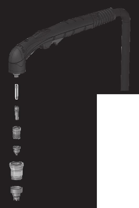
32 Fig. N

33 Fig. O 1.5mm Fig. P d
2N LiftIP. IO Extender. Communicator for Lifts. Version
 2N LiftIP Communicator for Lifts IO Extender Version 2.4.0 www.2n.cz Description The IO extender helps you extend 2N LiftIP with 1 input and 2 outputs. The purpose of the input is to cancel the rescue
DATA SHEET. BC516 PNP Darlington transistor. technický list DISCRETE SEMICONDUCTORS Apr 23. Product specification Supersedes data of 1997 Apr 16
 zákaznická linka: 840 50 60 70 DISCRETE SEMICONDUCTORS DATA SHEET book, halfpage M3D186 Supersedes data of 1997 Apr 16 1999 Apr 23 str 1 Dodavatel: GM electronic, spol. s r.o., Křižíkova 77, 186 00 Praha
ISTRUZIONE MANUALE. (EN)...pag. 5. (EL)... pag. 43 (NL)... pag. 49 (HU)... pag. 55 (RO)... pag. 60 (SV)... pag. 66 (DA)... pag. 71 (NO)... pag.
...pag. 5. (EL)... pag. 43 (NL)... pag. 49 (HU)... pag. 55 (RO)... pag. 60 (SV)... pag. 66 (DA)... pag. 71 (NO)... pag.") MANUALE ISTRUZIONE (EN) (IT) (FR) (ES) (DE) (RU) (PT) (EL) (NL) (HU) (RO) (SV) (DA) (EN)...pag. 5 (IT)... pag. 10 (FR)... pag. 15 (ES)... pag. 21 (DE)... pag. 26 (RU)... pag. 32 (PT)... pag. 38 EXPLANATION
MANUALE ISTRUZIONE (EN) (IT) (FR) (ES) (DE) (RU) (PT) (EL) (NL) (HU) (RO) (SV) (DA) (EN)...pag. 5 (IT)... pag. 10 (FR)... pag. 15 (ES)... pag. 21 (DE)... pag. 26 (RU)... pag. 32 (PT)... pag. 38 EXPLANATION
Litosil - application
 Litosil - application The series of Litosil is primarily determined for cut polished floors. The cut polished floors are supplied by some specialized firms which are fitted with the appropriate technical
SMART CUT 42 COMPRESOR
 SMART CUT 42 COMPRESOR INSTRUCCIONES DE UTILIZACIÓN EQUIPO DE CORTE POR PLASMA MANUAL Código: 2717212 Revisión 0, Enero 2018 (EN)...pag. 5 (IT)... pag. 10 (FR)... pag. 15 (ES)... pag. 21 (DE)... pag. 26
SERVISNÍ MANUÁL PEGAS 250 E CEL OVO SERVICE MANUAL PEGAS 250 E CEL OVO
 MG136-1 PEGAS 250 E CEL OVO SERVICE MANUAL page 1 SERVISNÍ MANUÁL PEGAS 250 E CEL OVO SERVICE MANUAL PEGAS 250 E CEL OVO 1. VAROVÁNÍ WARNING UPOZORNĚNÍ Pouze osoba splňující kvalifikaci danou zákonem je
UŽIVATELSKÁ PŘÍRUČKA
 UŽIVATELSKÁ PŘÍRUČKA Plni víry a naděje míříme kupředu. S odhodláním zlepšujeme své dovednosti. Zapomeňte na zklamání, ale nikoli na svůj nevyužitý potenciál. Touha překonat sám sebe a dosáhnout hranice
UPM3 Hybrid Návod na ovládání Čerpadlo UPM3 Hybrid 2-5 Instruction Manual UPM3 Hybrid Circulation Pump 6-9
 www.regulus.cz UPM3 Hybrid Návod na ovládání Čerpadlo UPM3 Hybrid 2-5 Instruction Manual UPM3 Hybrid Circulation Pump 6-9 CZ EN UPM3 Hybrid 1. Úvod V továrním nastavení čerpadla UPM3 Hybrid je profil PWM
Název společnosti: VPK, s.r.o. Vypracováno kým: Ing. Michal Troščak Telefon: Datum:
 Pozice Počet Popis 1 SCALA2 3-45 A Datum: 2.7.217 Výrobní č.: 98562862 Grundfos SCALA2 is a fully integrated, self-priming, compact waterworks for pressure boosting in domestic applications. SCALA2 incorporates
(EL)... pag. 30 (NL)... pag. 34 (HU)... pag. 37 (RO)... pag. 41 (SV)... pag. 44 (DA)... pag. 48 (NO)... pag. 51 (AR)
... pag. 30 (NL)... pag. 34 (HU)... pag. 37 (RO)... pag. 41 (SV)... pag. 44 (DA)... pag. 48 (NO)... pag. 51 (AR)") MANUALE ISTRUZIONE (EN) (IT) (FR) (ES) (DE) (RU) (PT) (EL) (NL) (HU) (RO) (SV) (EN)...pag. 5 (IT)...pag. 8 (FR)... pag. 12 (ES)... pag. 15 (DE)... pag. 19 (RU)... pag. 22 (PT)... pag. 26 EXPLANATION OF
MANUALE ISTRUZIONE (EN) (IT) (FR) (ES) (DE) (RU) (PT) (EL) (NL) (HU) (RO) (SV) (EN)...pag. 5 (IT)...pag. 8 (FR)... pag. 12 (ES)... pag. 15 (DE)... pag. 19 (RU)... pag. 22 (PT)... pag. 26 EXPLANATION OF
USER'S MANUAL FAN MOTOR DRIVER FMD-02
 USER'S MANUAL FAN MOTOR DRIVER FMD-02 IMPORTANT NOTE: Read this manual carefully before installing or operating your new air conditioning unit. Make sure to save this manual for future reference. FMD Module
GUIDELINES FOR CONNECTION TO FTP SERVER TO TRANSFER PRINTING DATA
 GUIDELINES FOR CONNECTION TO FTP SERVER TO TRANSFER PRINTING DATA What is an FTP client and how to use it? FTP (File transport protocol) - A protocol used to transfer your printing data files to the MAFRAPRINT
Název společnosti: VPK, s.r.o. Vypracováno kým: Ing. Michal Troščak Telefon: Datum:
 Počet 1 SCALA2 3-45 A Datum: 2.7.217 Výrobní č.: 98562862 Grundfos SCALA2 is a fully integrated, self-priming, compact waterworks for pressure boosting in domestic applications. SCALA2 incorporates integrated
TECHNICKÝ LIST řada mechanických odvaděčů kondenzátu AUTODRAIN TECHNICAL DATA SHEET for mechanical autodrain equipment AUTODRAIN
 Popis: Nádoba s mechanickým plovákem k odstraňování pevných nečistot, vody, aerosolů, uhlovodíků, prachu oddělených separátory KING AIR se systémem stlačeného vzduchu. Rozdělení dle využití instalace:
SERVICE MANUAL PEGAS 250 E CEL SERVISNÍ MANUÁL PEGAS 250 E CEL
 MG-011-05 PEGAS 250 E CEL SERVICE MANUAL page 1 SERVISNÍ MANUÁL PEGAS 250 E CEL SERVICE MANUAL PEGAS 250 E CEL 1. VAROVÁNÍ WARNING UPOZORNĚNÍ Pouze osoba splňující kvalifikaci danou zákonem je oprávněna
(NL)... pag. 26 (EL)... pag. 29 (RO)... pag. 33 (SV)... pag. 36 (CS)... pag. 39 (HR-SR)... pag. 42 (PL)... pag. 45 (AR)
... pag. 26 (EL)... pag. 29 (RO)... pag. 33 (SV)... pag. 36 (CS)... pag. 39 (HR-SR)... pag. 42 (PL)... pag. 45 (AR)") MANUALE ISTRUZIONE (EN) (IT) (FR) (ES) (DE) (RU) (PT) (NL) (EL) (RO) (SV) (CS) (EN)...pag. 5 (IT)...pag. 8 (FR)... pag. 11 (ES)... pag. 14 (DE)... pag. 17 (RU)... pag. 20 (PT)... pag. 23 EXPLANATION OF
MANUALE ISTRUZIONE (EN) (IT) (FR) (ES) (DE) (RU) (PT) (NL) (EL) (RO) (SV) (CS) (EN)...pag. 5 (IT)...pag. 8 (FR)... pag. 11 (ES)... pag. 14 (DE)... pag. 17 (RU)... pag. 20 (PT)... pag. 23 EXPLANATION OF
2N Voice Alarm Station
 2N Voice Alarm Station 2N Lift1 Installation Manual Version 1.0.0 www.2n.cz EN Voice Alarm Station Description The 2N Voice Alarm Station extends the 2N Lift1/ 2N SingleTalk with an audio unit installed
Uživatelská příručka. USB Charger UCH20
 Uživatelská příručka USB Charger UCH20 Obsah Úvod...3 USB Charger popis... 3 Používání nabíječky USB... 4 Nabíjení zařízení... 4 Právní informace... 5 Declaration of Conformity...6 2 Úvod USB Charger popis
:= = := :=.. := := := := ρ := := α := π α = α = := = :=
 := = := :=.. := := := := ρ := := α := π α = α = := = := := α := α := = := α := := α = = ρ ρ := := := = := = := := := + + := + + := + := := := := + + := + + := + = = = :=.. := η := η := := π = :=.. :=,
(EN) (DE)... pag. 22 (NO)... pag. 58 (BG)... pag. 93 (DE) (RU) (PT) (NL)... pag. 38 (SL)... pag. 74
 (DE)... pag. 22 (NO)... pag. 58 (BG)... pag. 93 (DE) (RU) (PT) (NL)... pag. 38 (SL)... pag. 74") (EN) (IT) (FR) (ES) (DE) (RU) (PT) (EL) (NL) (HU) (RO) (SV) Cod.954454 (EN)...pag. 6 (HU)... pag. 42 (HR-SR)... pag. 77 (IT)... pag. 10 (RO)... pag. 46 (LT)... pag. 81 (FR)... pag. 14 (SV)... pag. 50 (ET)...
(EN) (IT) (FR) (ES) (DE) (RU) (PT) (EL) (NL) (HU) (RO) (SV) Cod.954454 (EN)...pag. 6 (HU)... pag. 42 (HR-SR)... pag. 77 (IT)... pag. 10 (RO)... pag. 46 (LT)... pag. 81 (FR)... pag. 14 (SV)... pag. 50 (ET)...
EN IT FR ES DE RU PT EL NL HU RO SV DA NO FI CS SK SL HR-SR LT ET LV BG PL AR
 EN IT FR ES DE RU PT EL NL HU RO SV DA NO FI CS SK SL HR-SR LT ET LV BG PL AR (EN) دليل التشغيل INSTRUCTION MANUAL (IT) MANUALE D ISTRUZIONE (FR) MANUEL D INSTRUCTIONS (ES) MANUAL DE INSTRUCCIONES (DE)
(EL)... pag. 26 (NL)... pag. 29 (HU)... pag. 33 (RO)... pag. 36 (SV)... pag. 39 (DA)... pag. 42 (NO)... pag. 45 (AR)
... pag. 26 (NL)... pag. 29 (HU)... pag. 33 (RO)... pag. 36 (SV)... pag. 39 (DA)... pag. 42 (NO)... pag. 45 (AR)") MANUALE ISTRUZIONE (EN) (IT) (FR) (ES) (DE) (RU) (PT) (EL) (NL) (HU) (RO) (SV) (EN)...pag. 5 (IT)...pag. 8 (FR)... pag. 11 (ES)... pag. 14 (DE)... pag. 17 (RU)... pag. 20 (PT)... pag. 23 EXPLANATION OF
MANUALE ISTRUZIONE (EN) (IT) (FR) (ES) (DE) (RU) (PT) (EL) (NL) (HU) (RO) (SV) (EN)...pag. 5 (IT)...pag. 8 (FR)... pag. 11 (ES)... pag. 14 (DE)... pag. 17 (RU)... pag. 20 (PT)... pag. 23 EXPLANATION OF
SPECIFICATION FOR ALDER LED
 SPECIFICATION FOR ALDER LED MODEL:AS-D75xxyy-C2LZ-H1-E 1 / 13 Absolute Maximum Ratings (Ta = 25 C) Parameter Symbol Absolute maximum Rating Unit Peak Forward Current I FP 500 ma Forward Current(DC) IF
EN IT FR ES DE RU PT EL NL HU RO SV DA NO FI CS SK SL HR-SR LT ET LV BG PL AR
 EN IT FR ES DE RU PT EL NL HU RO SV DA NO FI CS SK SL HR-SR LT ET LV BG PL AR (EN) دليل التشغيل INSTRUCTION MANUAL (IT) MANUALE D ISTRUZIONE (FR) MANUEL D INSTRUCTIONS (ES) MANUAL DE INSTRUCCIONES (DE)
Size / Světlost : DN 1/4 to 4 / DN 1/4 až 4
 Size / Světlost : 1/4 to 4 / 1/4 až 4 Ends / Konce : Threaded BSP / Závitové BSP Min. Temperature / Minimální teplota : -20 C Max. Temperature / Maximální teplota : +180 C Max. Pressure / Maximální tlak
ADDRESS CONVERSION TABLE FOR MANUAL SETTING
 - (06-57) - ADDRESS CVERSI TABLE FOR MANUAL SETTING In the case of a multiple refrigerant system, each refrigerant system should be set an exclusive refrigerant. Conversion table of refrigerant and rotary
EN IT FR ES DE RU PT EL NL HU RO SV DA NO FI CS SK SL HR-SR LT ET LV BG PL AR
 EN IT FR ES DE RU PT EL NL HU RO SV DA NO FI CS SK SL HR-SR LT ET LV BG PL AR (EN) دليل التشغيل INSTRUCTION MANUAL (IT) MANUALE D ISTRUZIONE (FR) MANUEL D INSTRUCTIONS (ES) MANUAL DE INSTRUCCIONES (DE)
MA251 (cz_en) Operating instructions. MA251 (cz_en) Montážní návod. Krimpovací kleště PV-CZM... pro MC3, MC4 a MC4-EVO 2
 Operating instructions. MA251 (cz_en) Montážní návod. Krimpovací kleště PV-CZM... pro MC3, MC4 a MC4-EVO 2") MA251 (cz_en) Montážní návod Krimpovací kleště PV-CZM... pro MC3, MC4 a MC4-EVO 2 MA251 (cz_en) Operating instructions Crimping pliers PV-CZM... for MC3, MC4 and MC4-EVO 2 Obsah Bezpečnostní pokyny...2
MA251 (cz_en) Montážní návod Krimpovací kleště PV-CZM... pro MC3, MC4 a MC4-EVO 2 MA251 (cz_en) Operating instructions Crimping pliers PV-CZM... for MC3, MC4 and MC4-EVO 2 Obsah Bezpečnostní pokyny...2
EN IT FR ES DE RU PT EL NL HU RO SV DA NO FI CS SK SL HR-SR LT ET LV BG PL AR
 EN IT FR ES DE RU PT EL NL HU RO SV DA NO FI CS SK SL HR-SR LT ET LV BG PL AR (EN) دليل التشغيل INSTRUCTION MANUAL (IT) MANUALE D ISTRUZIONE (FR) MANUEL D INSTRUCTIONS (ES) MANUAL DE INSTRUCCIONES (DE)
GB I F E D RU P GR NL H RO S DK N SF CZ SK SI HR/SCG LT EE LV BG PL
 GB I F E D RU P GR NL H RO S DK N SF CZ SK SI HR/SCG LT EE LV BG PL GB INSTRUCTION MANUAL I MANUALE D ISTRUZIONE F MANUEL D INSTRUCTIONS E MANUAL DE INSTRUCCIONES D BEDIENUNGSANLEITUNG RU РУКОВОДСТВО ПОЛЬЗОВАТЕЛЯ
Mechanika Teplice, výrobní družstvo, závod Děčín TACHOGRAFY. Číslo Servisní Informace Mechanika: 5-2013
 Mechanika Teplice, výrobní družstvo, závod Děčín TACHOGRAFY Servisní Informace Datum vydání: 20.2.2013 Určeno pro : AMS, registrované subj.pro montáž st.měř. Na základě SI VDO č./datum: Není Mechanika
1-AYKY. Instalační kabely s Al jádrem. Standard TP-KK-133/01, PNE 347659-3. Konstrukce. Použití. Vlastnosti. Installation cables with Al conductor
 Instalační kabely s Al jádrem Installation cables with Al conductor Standard TP-KK-133/01, PNE 347659-3 4 3 2 1 Konstrukce Construction 1 Hliníkové jádro Aluminium conductor 2 Izolace PVC 3 Výplňový obal
Hi-Res Audio/DNC Headset MDR-NC750
 Uživatelská příručka Hi-Res Audio/DNC Headset MDR-NC750 Obsah Začínáme...3 Úvod...3 Přehled... 3 Základy práce...4 Nošení náhlavní soupravy...4 Připojení náhlavní soupravy k vašemu zařízení... 4 Nastavení
TechoLED H A N D B O O K
 TechoLED HANDBOOK Světelné panely TechoLED Úvod TechoLED LED světelné zdroje jsou moderním a perspektivním zdrojem světla se širokými možnostmi použití. Umožňují plnohodnotnou náhradu žárovek, zářivkových
Uživatelská příručka. Xperia P TV Dock DK21
 Uživatelská příručka Xperia P TV Dock DK21 Obsah Úvod...3 Přehled zadní strany stanice TV Dock...3 Začínáme...4 Správce LiveWare...4 Upgradování aplikace Správce LiveWare...4 Použití stanice TV Dock...5
20 ka / 1 s (dle typu cívky) přirozené
 přirozené") KATALOG CATALOGUE 051/03/2013 VÝKONOVÝ REAKTOR NN, NASTAVITELNÝ LOW VOLTAGE POWER REACTOR COIL, ADJUSTABLE pro napětí do 1000 V for voltages up to 1000V TYP LNN ISO 9001:2009 ISO 14001:2005 VŠEOBECNĚ Výkonový
KATALOG CATALOGUE 051/03/2013 VÝKONOVÝ REAKTOR NN, NASTAVITELNÝ LOW VOLTAGE POWER REACTOR COIL, ADJUSTABLE pro napětí do 1000 V for voltages up to 1000V TYP LNN ISO 9001:2009 ISO 14001:2005 VŠEOBECNĚ Výkonový
NOPOVIC NHXH FE180 E90
 Kabely se sníženým požárním nebezpečím(lfhc kabely) se zachováním funkční integrity systému kabelové trasy E90 NOPOVIC NHXH FE180 E90 Low fire-hazard cables (LFHC cables) with system integrity in case
MIG-MAG EN IT FR ES DE RU PT EL NL HU RO SV DA NO FI CS SK SL HR-SR LT ET LV BG PL AR
 EN IT FR ES DE RU PT EL NL HU RO SV DA NO FI CS SK SL HR-SR LT ET LV BG PL AR (EN) دليل التشغيل INSTRUCTION MANUAL (IT) MANUALE D ISTRUZIONE (FR) MANUEL D INSTRUCTIONS (ES) MANUAL DE INSTRUCCIONES (DE)
SERVISNÍ MANUÁL PEGAS 200 AC- DC PULSE OVO SERVICE MANUAL PEGAS 200 AC- DC PULSE OVO
 MG35-2 PEGAS 200 AC- PULSE OVO SERVICE MANUAL page /0 SERVISNÍ MANUÁL PEGAS 200 AC- PULSE OVO SERVICE MANUAL PEGAS 200 AC- PULSE OVO. VAROVÁNÍ WARNING UPOZORNĚNÍ Pouze osoba splňující kvalifikaci danou
ROLZ-2. Portable AV/Conference Center. Assembly Instructions
 1 ROLZ-2 Portable AV/Conference Center Assembly Instructions Rolz-2 Portable AV/Conference Center Part Drawing Description Qty Part Drawing Description Qty Hardware List A 1 ½ Flat Head Screw 2 EA P-1
MG125-4 PEGAS 200 AC-DC PULSE SERVICE MANUAL
 MG25-4 PEGAS 200 AC- PULSE SERVICE MANUAL page SERVISNÍ MANUÁL PEGAS 200 AC- PULSE SERVICE MANUAL PEGAS 200 AC- PULSE. VAROVÁNÍ WARNING UPOZORNĚNÍ Pouze osoba splňující kvalifikaci danou zákonem je oprávněna
Použití. Application. Field of application. Rozsah použití A.1.1
 Uzavírací ventil V46.2 DN 10 50, PN 100 400 Regulační ventil V40.2 DN 10 50, PN 100 400 Globe valve V46.2 DN 10 50, PN 100 400 Control valve V40.2 DN 10 50, PN 100 400 Použití Uzavírací ventil (V 46.2)
EN IT FR ES DE RU PT EL NL HU RO SV DA NO FI CS SK SL HR-SR LT ET LV BG PL AR
 EN IT FR ES DE RU PT EL NL HU RO SV DA NO FI CS SK SL HR-SR LT ET LV BG PL AR (EN) دليل التشغيل INSTRUCTION MANUAL (IT) MANUALE D ISTRUZIONE (FR) MANUEL D INSTRUCTIONS (ES) MANUAL DE INSTRUCCIONES (DE)
obal manuálu, asi něco podobného jako u LC 100 asi by to chtělo lepší obrázek!!! FYTOSCOPE FS130 Instruction Guide
 obal manuálu, asi něco podobného jako u LC 100 asi by to chtělo lepší obrázek!!! FYTOSCOPE FS130 Instruction Guide možná tohle trochu zmenšit a dát sem i to varování LED RADIATION co je na další straně
ELEKTROMOTORY SÉRIE CHT CHT ELECTRIC MOTORS
 ELEKTROMOTORY SÉRIE CHT CHT ELECTRIC MOTORS ÚVOD CHT série elektromotor byla vyvinuta pro p ipojení na p evodovky a z tohoto d vodu mají veškeré mechanické a elektrické charakteristiky p izp sobeny práv
2N LiftIP. Voice Alarm Station. Communicator for Lifts. Version
 2N LiftIP Communicator for Lifts Voice Alarm Station Version 2.4.0 www.2n.cz Description The 2N Voice Alarm Station is a switch that helps you extend 2N LiftIP with one or more audio units installed on
MG121-4 PEGAS 200 AC-DC SERVICE MANUAL
 MG2-4 PEGAS 200 AC- SERVICE MANUAL page SERVISNÍ MANUÁL PEGAS 200 AC- SERVICE MANUAL PEGAS 200 AC-. VAROVÁNÍ WARNING UPOZORNĚNÍ Pouze osoba splňující kvalifikaci danou zákonem je oprávněna opravovat stroj.
 11.12. 100 ΕΙΣΟΔΟΣ = E / ENTRANCE = E = = 1174 550 ΤΥΠΟΠΟΙΗΜΕΝΟ ΚΥ = 2000 (ΕΠΙΛΟΓΗ: 2100) / CH STANDARD = 2000 (OPTIONAL: 2100) 243 50 ΚΥ/CH + 293 ΚΥ/CH +103 100 ΚΥ /CH 6 11 6 20 100 0,25 ΚΑ (CO) + 45
RIMINI. Samozavírací hydraulické závěsy Self-closing hydraulic hinges
 3 RIMINI Samozavírací hydraulické závěsy Self-closing hydraulic hinges Bartosini s.r.o. Kancelář: Karvinská 1897, 737 01 Český Těšín tel.: +420 602 322 276; e-mail: bartosini@bartosini.cz WWW.BARTOSINI.CZ
ZB5AV013 bílá signální hlavice Ø22 plná čočka pro integ. LED
 Characteristics bílá signální hlavice Ø22 plná čočka pro integ. LED Doplňky CAD celková šířka CAD celková výška CAD celková hloubka Hmotnost přístroje Označení skříně Označení el. složení Prostředí Stupeň
Izolační manipulační tyče typ IMT IMT Type Insulated Handling Rod
 KATALOG CATALOGUE 024/09/2011 IZOLAČNÍ MANIPULAČNÍ TYČ INSULATED HANDLING ROD TYP IMT KOVOVÁ MANIPULAČNÍ TYČ METALLIC HANDLING ROD TYP KMT ISO 9001:2009 ISO 14001:2005 Izolační manipulační tyče typ IMT
PC/104, PC/104-Plus. 196 ept GmbH I Tel. +49 (0) / I Fax +49 (0) / I I
 / I Fax +49 (0) / I I") E L E C T R O N I C C O N N E C T O R S 196 ept GmbH I Tel. +49 (0) 88 61 / 25 01 0 I Fax +49 (0) 88 61 / 55 07 I E-Mail sales@ept.de I www.ept.de Contents Introduction 198 Overview 199 The Standard 200
E L E C T R O N I C C O N N E C T O R S 196 ept GmbH I Tel. +49 (0) 88 61 / 25 01 0 I Fax +49 (0) 88 61 / 55 07 I E-Mail sales@ept.de I www.ept.de Contents Introduction 198 Overview 199 The Standard 200
Pokyny k použití. Model-300. Napájecí zdroj. Návod na obsluhu Operating Instructions. se systémem Aquacontrol Napájací zdroj
 Pokyny k použití Model-300 Návod na obsluhu Operating Instructions Napájecí zdroj se systémem Napájací zdroj so systémom Power Supply with System BK 0011900 / PC AQUACONTROL Kryt aquacontrol Kryt aquacontrol
Střední průmyslová škola strojnická Olomouc, tř.17. listopadu 49
 Střední průmyslová škola strojnická Olomouc, tř.17. listopadu 49 Výukový materiál zpracovaný v rámci projektu Výuka moderně Registrační číslo projektu: CZ.1.07/1.5.00/34.0205 Šablona: III/2 Anglický jazyk
User manual SŘHV Online WEB interface for CUSTOMERS June 2017 version 14 VÍTKOVICE STEEL, a.s. vitkovicesteel.com
 1/ 11 User manual SŘHV Online WEB interface for CUSTOMERS June 2017 version 14 2/ 11 Contents 1. MINIMUM SYSTEM REQUIREMENTS... 3 2. SŘHV ON-LINE WEB INTERFACE... 4 3. LOGGING INTO SŘHV... 4 4. CONTRACT
Introduction to MS Dynamics NAV
 Introduction to MS Dynamics NAV (Item Charges) Ing.J.Skorkovský,CSc. MASARYK UNIVERSITY BRNO, Czech Republic Faculty of economics and business administration Department of corporate economy Item Charges
USER'S MANUAL FAN MOTOR DRIVER FMD-01, FMD-03
 USER'S MANUAL FAN MOTOR DRIVER FMD-01, FMD-03 IMPORTANT NOTE: Read this manual carefully before installing or operating your new air conditioning unit. Make sure to save this manual for future reference.
Switch on the appropriate breaker and verify that the light is working properly.
 Package contents Name: MONA WALL PC970 wall light 445 Components included with unit: glass shade with light source, 1x metal light body, 1x wall mount, 3x terminal connectors, 2x hex screws M5, 1x hex
FIRE INVESTIGATION. Střední průmyslová škola Hranice. Mgr. Radka Vorlová. 19_Fire investigation CZ.1.07/1.5.00/
 FIRE INVESTIGATION Střední průmyslová škola Hranice Mgr. Radka Vorlová 19_Fire investigation CZ.1.07/1.5.00/34.0608 Výukový materiál Číslo projektu: CZ.1.07/1.5.00/21.34.0608 Šablona: III/2 Inovace a zkvalitnění
Gymnázium, Brno, Slovanské nám. 7 WORKBOOK. Mathematics. Teacher: Student:
 WORKBOOK Subject: Teacher: Student: Mathematics.... School year:../ Conic section The conic sections are the nondegenerate curves generated by the intersections of a plane with one or two nappes of a cone.
VENTIL ZPĚTNÝ JEDNODÍLNÝ ZÁVITOVÝ Teplota max.-20 C/150 C TYP C09.Z PN16 DN ¼ -4
 VENTIL ZPĚTNÝ JEDNODÍLNÝ ZÁVITOVÝ Teplota max.-20 C/150 C TYP C09.Z PN16 DN ¼ -4 Size / Světlost : DN 1/4" to 4" / DN 1/4" až 4" Ends / Konce : Female-Female BSP / Závitové, vnitřní-vnitřní závit BSP Min.
ZÓNOVÉ VENTILY S VRATNOU PRUŽINOU dvoucestné VZP 2XX 230 1P 001 třícestné VZP 3XX 230 1P 001
 Návod na instalaci a použití ZÓNOVÉ VENTILY S VRATNOU PRUŽINOU dvoucestné VZP 2XX 230 1P 001 třícestné VZP 3XX 230 1P 001 CZ verze 1.2 Popis: Zónové ventily s vratnou pružinou jsou určeny do hydraulických
Návod k obsluze a montáži N129/R04 (10.03.14 ) SUŠÁK NA RUCE
 SUŠÁK NA RUCE") Návod k obsluze a montáži N129/R04 (10.03.14 ) SUŠÁK NA RUCE Čtěte prosím pozorně informace uvedené v tomto návodu, který obsahuje důležité pokyny pro bezpečnou montáž, použití a údržbu jednotky. Uchovávejte
Návod k obsluze a montáži N129/R04 (10.03.14 ) SUŠÁK NA RUCE Čtěte prosím pozorně informace uvedené v tomto návodu, který obsahuje důležité pokyny pro bezpečnou montáž, použití a údržbu jednotky. Uchovávejte
Ventil zpětný Z15.1 DN 10 50, PN 100 400 Piston check valve Z15.1 DN 10 50, PN 100 400
 DN 10 50, PN 100 400 DN 10 50, PN 100 400 Použití Zpětný ventil je samočinná armatura, zamezující zpětnému proudění provozní tekutiny, určená pro vodu, vodní páru, plyny i jiné provozní tekutiny používané
GENERAL INFORMATION RUČNÍ POHON MANUAL DRIVE MECHANISM
 KATALOG CATALOGUE RUČNÍ POHONY PRO VENKOVNÍ PŘÍSTROJE, MONTÁŽ NA BETONOVÉ SLOUPY MANUAL DRIVE MECHANISM FOR THE ACTUATION OF OUTDOOR TYPE SWITCHING DEVICES MOUNTED ON THE CONCRETE POLES TYP RPV ISO 9001:2009
WL-5480USB. Quick Setup Guide
 Quick Setup Guide 1 Czech 7 Install Utility Software Note1: Before installing the utility software, DO NOT inserts the into your computer. If the adapter is inserted already, Windows will detect the adapter
INSTALAČNÍ NÁVOD OPERATING INSTRUCTION
 LED PRODISC II + LED PRODISC II MINI + LED PRODISC II MAXI INSTALAČNÍ NÁVOD OPERATING INSTRUCTION 4000944x 4000945x 4000940x 4000941x 4000946x 4000947x Prodisc II Mini Prodisc II Mini + MW senzor Prodisc
235 Montážní šablona Přiložte tuto šablonu na zeď.
 A B 235 Montážní šablona Přiložte tuto šablonu na zeď. UPOZORNĚNÍ: - D PŘIPOJENÍ 1. Upevněte základní desku na stěnu. 2. Upevněte na stěnu pomocí ½ šroubů. 3. Připojení: A. Připojte fázový vodič (černá,
INDUCTION HEATING CAPACITORS KONDENZÁTORY PRO INDUKČNÍ OHŘEV
 INDUCTION HEATING CAPACITORS KONDENZÁTORY PRO INDUKČNÍ OHŘEV SCA - 2012-1 CONTENTS OBSAH 03 General technical information Obecné technické informace 04 Medium Frequency Capacitors - water cooled, up to
Automatika na dávkování chemie automatic dosing
 Automatika na dávkování chemie automatic dosing Swimmingpool Technology Autodos 700 Automatické dávkování Autodos Autodos automatic dosing Autodos 700 je jedno-kanálové zaøízení, pro mìøení a dávkování.
harvia griffin COLOUR LIGHT Control unit Ridici jednotka
 harvia griffin COLOUR LIGHT Control unit Ridici jednotka 13082008 These instructions for installation and use are intended for owners of colour light units and control units and for electricians responsible
nkt instal CYKY 450/750 V Instalační kabely Konstrukce Použití Vlastnosti Installation cables Construction 2 Izolace PVC Měděná plná holá jádra
 Instalační kabely Installation cables Standard PN-KV-061-00 4 3 2 1 Konstrukce Construction 1 Měděná plná holá jádra Solid plain copper conductors 2 Izolace PVC 3 Výplňový obal 4 Plášť PVC PVC insulation
AIC ČESKÁ REPUBLIKA CZECH REPUBLIC
 ČESKÁ REPUBLIKA CZECH REPUBLIC ŘÍZENÍ LETOVÉHO PROVOZU ČR, s.p. Letecká informační služba AIR NAVIGATION SERVICES OF THE C.R. Aeronautical Information Service Navigační 787 252 61 Jeneč A 1/14 20 FEB +420
3 Výplňový obal. 4 Plášť PE. Bedding
 Instalační kabely s Cu jádrem Installation cables with Cu conductor Standard VDE0276 T.603-5G-2 4 3 2 1 Konstrukce Construction 1 Měděné jádro Copper conductor 2 Izolace XLPE XLPE insulation 3 Výplňový
2. BLOKOVÉ SCHÉMA ELECTRICAL PRINCIPLE DRAWING
 MG062-2 SERVISNÍ MANUÁL / SERVICE MANUAL ALFIN 150 TP page 1 SERVISNÍ MANUÁL ALFIN 150 TP SERVICE MANUAL ALFIN 150 TP 1. VAROVÁNÍ WARNING UPOZORNĚNÍ Pouze osoba splňující kvalifikaci danou zákonem je oprávněna
Quick Start Guide. Clear. Rychlý průvodce nastavením
 CZ EN Quick Start Guide Clear Rychlý průvodce nastavením Measurement Měření Před Fully prvním charge použitím the blood plně pressure dobijte monitor baterii before přístroje. first use. 1 Rest your bare
DC circuits with a single source
 Název projektu: utomatizace výrobních procesů ve strojírenství a řemeslech egistrační číslo: Z..07/..0/0.008 Příjemce: SPŠ strojnická a SOŠ profesora Švejcara Plzeň, Klatovská 09 Tento projekt je spolufinancován
NOPOVIC 1-CXKH-V B2cas1d0 a1 FE180 E60 P60-R PS60
 Kabely se sníženým požárním nebezpečím (LFHC kabely) se zachováním funkční integrity systému kabelové trasy P30-R, P60-R Low fire-hazard cables (LFHC cables) with system integrity in case of fire E30,
FILTR ZÁVITOVÝ CELONEREZOVÝ Teplota max.-30 C/200 C TYP D PN16 DN1/4-2. Size / Světlost : DN 1/4 to 2 / DN 1/4 až 2 Ends / Konce :
 FILTR ZÁVITOVÝ CELONEREZOVÝ Teplota max.-30 C/200 C TYP D71 137 PN16 DN1/4-2 Size / Světlost : DN 1/4 to 2 / DN 1/4 až 2 Ends / Konce : Female Female BSP / Závitové BSP (vnitřní-vnitřní) Min. Temperature
3 Výplňový obal. 4 Plášť PE. Bedding
 Instalační kabely s Al jádrem Installation cables with Al conductor Standard VDE0276 T.603-5G-2 4 3 2 1 Konstrukce Construction 1 Hliníkové jádro Aluminium conductor 2 Izolace XLPE XLPE insulation 3 Výplňový
NY2Y 0,6/1 kv. Instalační kabely s Cu jádrem VDE 0276 T.603-3G-2. Konstrukce. Použití. Vlastnosti. Installation cables with Cu conductor.
 Instalační kabely s Cu jádrem Installation cables with Cu conductor Standard VDE 0276 T.603-3G-2 4 3 2 1 Konstrukce Construction 1 Měděné jádro Copper conductor 2 Izolace PVC PVC insulation 3 Výplňový
topter AKTIVNÍ OCHRANA Leading Electrotechnology
 topter AKTIVNÍ OCHRANA Leading Electrotechnology topter Aktivní ochrana Průmyslové zásuvky IP44, IP66/IP67 P TECHNICKÉ PARAMETRY e shodě s normami EN 60309- IEC 60309- EN 60309-2 IEC 60309-2 EN 60529 IEC
Instalační kabely. Installation cables NYM 300/500 V. Konstrukce: Construction: Použití: Application: Vlastnosti: Properties: Standard: VDE
 Instalační kabely Installation cables Standard: VDE 0250-204 4 3 2 1 Konstrukce: Construction: 1 Měděná plná holá jádra, třída 1 dle ČSN EN 60228 Solid plain copper conductors, class 1 acc. to ČSN EN 60228
3 Výplňový obal. 4 Plášť PE. Bedding
 Instalační kabely s Al jádrem Installation cables with Al conductor Standard TP-KK-145/03 4 3 2 1 Konstrukce Construction 1 Hliníkové jádro Aluminium conductor 2 Izolace XLPE XLPE insulation 3 Výplňový
2N Lift8 Audio unit machine room
 2N Lift8 Audio unit machine room Brief Manual Version 3.0.0 www.2n.cz The machine room audio unit is intended for installation in the machine room or as an intercom solution located in the reception.
Instalační kabely s koncentrickým vodičem a Al jádrem
 Instalační kabely s koncentrickým vodičem a Al jádrem Installation screened cables with Al conductor NAYCWY 0,6/1 kv Standard VDE 0276 T.603-3G-1 5 4 3 2 1 Konstrukce Construction 1 Hliníkové jádro Aluminium
Light (glass base with power cord and Ehmann dimmer, reflector, glass globe), light source, cotton gloves, installation manual
, light source, cotton gloves, installation manual") Package contents Name: BALLOONS PC858 Table light 607 850 Components included with unit: Light (glass base with power cord and Ehmann dimmer, reflector, glass globe), light source, cotton gloves, installation
Package contents Name: BALLOONS PC858 Table light 607 850 Components included with unit: Light (glass base with power cord and Ehmann dimmer, reflector, glass globe), light source, cotton gloves, installation
AUTOMATICKÝ DÁVKOVAČ Harvia. Návod na instalaci a použití instructions for installation and Use
 AUTOMATICKÝ DÁVKOVAČ Harvia Návod na instalaci a použití instructions for installation and Use 15122011 CZ EN 1. OBECNÉ INFORMACE 1. GENEraL Účelem Harvia automatického dávkovače je aplikovat vodu a směs
4Ever H A N D B O O K
 4Ever HANDBOOK Kancelářský systém 4Ever Úvod Základními stavebními komponenty podnoží jsou bočnice a podélné nosníky. Bočnice je tvořena nohami čtvercového průřezu 45 x 45 mm, spojovacím vodorovným bočním
Instalační kabely s koncentrickým vodičem a Cu jádrem
 Instalační kabely s koncentrickým vodičem a Cu jádrem Installation screened cables with Cu conductor NYCWY 0,6/1 kv Standard VDE 0276 T.603-3G-1 5 4 3 2 1 Konstrukce Construction 1 Měděné jádro Copper
Jmenovitá tloušťka pláště Nominal sheath thickness. 1x10 RE 1,0 1, x16 RE 1,0 1, x25 RE 1,2 1,
 Instalační kabely s Al jádrem Installation cables with Al conductor Standard VDE 0276 T.603-3G-2 4 3 2 1 Konstrukce Construction 1 Hliníkové jádro Aluminium conductor 2 Izolace PVC PVC insulation 3 Výplňový
âistiã vzduchu / Air Cleaner MF 06, MF 08, MF 10 ada ASISTENT, velikost G 1/8, G 1/4, G 3/8 ASISTENT Series, G 1/8, G 1/4, G 3/8 Sizes
 âistiã vzduchu / Air Cleaner MF 06, MF 08, MF 10 ASISTENT Series, G 1/8, G 1/4, G 3/8 Sizes PouÏití pfiístroj na ãi tûní vzduchu a oddûlení vody (více neï 90 %) Use Device for air cleaning and water separation
E-AY2Y 0,6/1 kv. Instalační kabely s Al jádrem. Konstrukce. Použití. Vlastnosti. Installation cables with Al conductor. Construction.
 Instalační kabely s Al jádrem Installation cables with Al conductor Standard OVE-K603 4 3 2 1 Konstrukce Construction 1 Hliníkové jádro Aluminium conductor 2 Izolace PVC 3 Výplňový obal 4 Plášť PE PVC
technický list TRANSIL TM 1.5KE6V8A/440A 1.5KE6V8CA/440CA www.gme.cz str 1
 Dodavatel: GM electronic, spol. s r.o., Křižíkova 77, 186 00 Praha 8 zákaznická linka: 840 50 60 70 technický list 1.5KE6V8A/440A 1.5KE6V8CA/440CA TRANSIL TM FEATURES PEAK PULSE POWER : 1500 W (10/1000µs)
VENTIL ZPĚTNÝ MEZIPŘÍRUBOVÝ PRUŽINOU - CELONEREZOVÝ Teplota max.-20 C/400 C TYP C09 PN 40 DN15-100
 VENTIL ZPĚTNÝ MEZIPŘÍRUBOVÝ PRUŽINOU - CELONEREZOVÝ Teplota max.-20 C/400 C TYP C09 PN 40 DN15-100 Size / Světlost : DN 15 to DN 100 / DN 15 až DN 100 Ends / Konce : Between flanges ISO PN 10/16/25/40
Připojení internetového modulu econet300 Do regulátoru ecomax 810P3-L TOUCH.
 Připojení internetového modulu econet300 Do regulátoru ecomax 810P3-L TOUCH. Connection of econet300 internet module to ecomax 810P3-L TOUCH Controller. Prosím ověřte verzi softwaru vašeho modulu ecomax.
SERVICE ADVISORY SA-5A
 V510 PROPELLER TYPE SERIES REPLACEMENT OF BLADE BEARING SEAL VRTULE TYPOVÉ ŘADY V510 VÝMĚNA TĚSNÍCÍ MANŽETY ULOŽENÍ LISTU 1. GENERAL A. This document provides disassembly and assembly procedure in the
TECHNICKÝ LIST řada STANDARD, HP, FZ TECHNICAL DATA SHEET for STANDARD, HP, FZ 2018 v1.0
 Popis: Separátory KingAir jsou určeny k odstraňování pevných nečistot, vody, aerosolů, uhlovodíků, pachů ze systému stlačeného vzduchu. Provedení zařízení umožňuje efektivní odstranění >99.9999% vody a
SERVISNÍ MANUÁL PEGAS 200 E SERVICE MANUAL PEGAS 200 E
 SERVISNÍ MANUÁL PEGAS 200 E SERVICE MANUAL PEGAS 200 E. VAROVÁNÍ WARNING UPOZORNĚNÍ Pouze osoba splňující kvalifikaci danou zákonem je oprávněna opravovat stroj. PŘED OTEVŘENÍM KRYTU STROJE JEJ ODPOJTE