INSTALLATION AND OPERATION MANUAL
|
|
|
- Stanislava Dušková
- před 6 lety
- Počet zobrazení:
Transkript
1 INSTALLATION AND OPERATION MANUAL System air conditioners FXDQ0M8VB FXDQ5M8VB

2 6 5a 5b 5a 5b 6 7 7
3 CE - ATITIKTIES-DEKLARACIJA CE - ATBILSTĪBAS-DEKLARĀCIJA CE - VYHLÁSENIE-ZHODY CE - UYUMLULUK-BİLDİRİSİ CE - IZJAVA O SKLADNOSTI CE - VASTAVUSDEKLARATSIOON CE - ДЕКЛАРАЦИЯ-ЗА-СЪОТВЕТСТВИЕ CE - IZJAVA-O-USKLAĐENOSTI CE - MEGFELELŐSÉGI-NYILATKOZAT CE - DEKLARACJA-ZGODNOŚCI CE - DECLARAŢIE-DE-CONFORMITATE CE - ERKLÆRING OM-SAMSVAR CE - ILMOITUS-YHDENMUKAISUUDESTA CE - PROHLÁŠENÍ-O-SHODĚ CE - DECLARAÇÃO-DE-CONFORMIDADE СЕ - ЗАЯВЛЕНИЕ-О-СООТВЕТСТВИИ CE - OPFYLDELSESERKLÆRING CE - FÖRSÄKRAN-OM-ÖVERENSTÄMMELSE CE - DECLARACION-DE-CONFORMIDAD CE - DICHIARAZIONE-DI-CONFORMITA CE - H ø H YMMOPºø H CE - DECLARATION-OF-CONFORMITY CE - KONFORMITÄTSERKLÄRUNG CE - DECLARATION-DE-CONFORMITE CE - CONFORMITEITSVERKLARING Daikin Europe N.V. 9 z vso odgovornostjo izjavlja, da so modeli klimatskih naprav, na katere se izjava nanaša: 0 kinnitab oma täielikul vastutusel, et käesoleva deklaratsiooni alla kuuluvad kliimaseadmete mudelid: декларира на своя отговорност, че моделите климатична инсталация, за които се отнася тази декларация: visiška savo atsakomybe skelbia, kad oro kondicionavimo prietaisų modeliai, kuriems yra taikoma ši deklaracija: ar pilnu atbildību apliecina, ka tālāk uzskaitīto modeįu gaisa kondicionētāji, uz kuriem attiecas šī deklarācija: vyhlasuje na vlastnú zodpovednosť, že tieto klimatizačné modely, na ktoré sa vzťahuje toto vyhlásenie: 5 tamamen kendi sorumluluğunda olmak üzere bu bildirinin ilgili olduğu klima modellerinin aşağıdaki gibi olduğunu beyan eder: 0 erklærer under eneansvar, at klimaanlægmodellerne, som denne deklaration vedrører: deklarerar i egenskap av huvudansvarig, att luftkonditioneringsmodellerna som berörs av denna deklaration innebär att: erklærer et fullstendig ansvar for at de luftkondisjoneringsmodeller som berøres av denne deklarasjon innebærer at: ilmoittaa yksinomaan omalla vastuullaan, että tämän ilmoituksen tarkoittamat ilmastointilaitteiden mallit: prohlašuje ve své plné odpovědnosti, že modely klimatizace, k nimž se toto prohlášení vztahuje: 5 izjavljuje pod isključivo vlastitom odgovornošću da su modeli klima uređaja na koje se ova izjava odnosi: 6 teljes felelőssége tudatában kijelenti, hogy a klímaberendezés modellek, melyekre e nyilatkozat vonatkozik: 0 declares under its sole responsibility that the air conditioning models to which this declar ation relates: 0 erklärt auf seine alleinige Verantwortung daß die Modelle der Klimageräte für die diese Erklärung bestimmt ist: 7 deklaruje na własną i wyłączną odpowiedzialność, że modele klimatyzatorów, których dotyczy niniejsza deklaracja: 8 declară pe proprie răspundere că aparatele de aer condiţionat la care se referă această declaraţie: 0 déclare sous sa seule responsabilité que les appareils d'air conditionné visés par la présente déclar ation: 0 verklaart hierbij op eigen exclusieve verantwoordelijkheid dat de airconditioning units waarop deze verklaring betrekking heeft: 05 declara baja su única responsabilidad que los modelos de aire acondicionado a los cuales hace ref erencia la declaración: 06 dichiara sotto sua responsabilità che i condizionatori modello a cui è riferita questa dichiarazione: 07 ËÏÒÓÂÈ Ì appleôîïâèûùèî ÙË Â ı ÓË fiùè Ù ÌÔÓÙ Ï ÙˆÓ ÎÏÈÌ ÙÈÛÙÈÎÒÓ Û ÛΠÒÓ ÛÙ ÔappleÔ Ó Ê ÚÂÙ È Ë apple ÚÔ Û ÏˆÛË: 08 declara sob sua exclusiva responsabilidade que os modelos de ar condicionado a que esta declaração se refere: 09 заявляет, исключительно под свою ответственность, что модели кондиционеров воздуха, к которым относится настоящее заявление: FXDQ0M8VB, FXDQ5M8VB 6 megfelelnek az alábbi szabvány(ok)nak vagy egyéb irányadó dokumentum(ok)nak, ha azokat előírás szerint használják: 7 spełniają wymogi następujących norm i innych dokumentów normalizacyjnych, pod warunkiem że używane są zgodnie z naszymi instrukcjami: 8 sunt în conformitate cu următorul (următoarele) standard(e) sau alt(e) document(e) normativ(e), cu condiţia ca acestea să fie utilizate în conformitate cu instrucţiunile noastre 9 skladni z naslednjimi standardi in drugimi normativi, pod pogojem, da se uporabljajo v skladu z našimi navodili: 0 on vastavuses järgmis(t)e standardi(te)ga või teiste normatiivsete dokumentidega, kui neid kasutatakse vastavalt meie juhenditele: съответстват на следните стандарти или други нормативни документи, при условие, че се използват съгласно нашите инструкции: atitinka žemiau nurodytus standartus ir (arba) kitus norminius dokumentus su sąlyga, kad yra naudojami pagal mūsų nurodymus: tad, ja lietoti atbilstoši ražotāja norādījumiem, atbilst sekojošiem standartiem un citiem normatīviem dokumentiem: sú v zhode s nasledovnou(ými) normou(ami) alebo iným(i) normatívnym(i) dokumentom(ami), za predpokladu, že sa používajú v súlade s našim návodom: 5 ürünün, talimatlarımıza göre kullanılması koşuluyla aşağıdaki standartlar ve norm belirten belgelerle uyumludur: 08 estão em conformidade com a(s) seguinte(s) norma(s) ou outro(s) documento(s) normativo(s), desde que estes sejam utilizados de acordo com as nossas instruções: 09 соответствуют следующим стандартам или другим нормативным документам, при условии их использования согласно нашим инструкциям: 0 overholder følgende standard(er) eller andet/andre retningsgivende dokument(er), forudsat at disse anvendes i henhold til vore instrukser: respektive utrustning är utförd i överensstämmelse med och följer följande standard(er) eller andra normgivande dokument, under förutsättning att användning sker i överensstämmelse med våra instruktioner: respektive utstyr er i overensstemmelse med følgende standard(er) eller andre normgivende dokument(er), under forutssetning av at disse brukes i henhold til våre instrukser: vastaavat seuraavien standardien ja muiden ohjeellisten dokumenttien vaatimuksia edellyttäen, että niitä käytetään ohjeidemme mukaisesti: za předpokladu, že jsou využívány v souladu s našimi pokyny, odpovídají následujícím normám nebo normativním dokumentům: 5 u skladu sa slijedećim standardom(ima) ili drugim normativnim dokumentom(ima), uz uvjet da se oni koriste u skladu s našim uputama: 0 are in conformity with the following standard(s) or other normative document(s), provided that these are used in accordance with our instructions: 0 der/den folgenden Norm(en) oder einem anderen Normdokument oder -dokumenten entspricht/entsprechen, unter der Voraussetzung, daß sie gemäß unseren Anweisungen eingesetzt werden: 0 sont conformes à la/aux norme(s) ou autre(s) document(s) normatif(s), pour autant qu'ils soient utilisés conformément à nos instructions: 0 conform de volgende norm(en) of één of meer andere bindende documenten zijn, op voorwaarde dat ze worden gebruikt overeenkomstig onze instructies: 05 están en conformidad con la(s) siguiente(s) norma(s) u otro(s) documento(s) normativo(s), siempre que sean utilizados de acuerdo con nuestras instrucciones: 06 sono conformi al(i) seguente(i) standard(s) o altro(i) documento(i) a carattere normativo, a patto che vengano usati in conformità alle nostre istruzioni: 07 Â Ó È Û ÌÊˆÓ Ì ÙÔ( ) ÎfiÏÔ ıô( ) appleúfiù appleô( ) ÏÏÔ ÁÁÚ ÊÔ( ) Î ÓÔÓÈÛÌÒÓ, applefi ÙËÓ appleúô applefiıâûë fiùè ÚËÛÈÌÔappleÔÈÔ ÓÙ È Û ÌÊˆÓ Ì ÙÈ Ô ËÁ Â Ì : EN605--0, 9 Direktive z vsemi spremembami. 0 Direktiivid koos muudatustega. Директиви, с техните изменения. Direktyvose su papildymais. Direktīvās un to papildinājumos. Smernice, v platnom znení. 5 Değiştirilmiş halleriyle Yönetmelikler. 0 Direktiver, med senere ændringer. Direktiv, med företagna ändringar. Direktiver, med foretatte endringer. Direktiivejä, sellaisina kuin ne ovat muutettuina. v platném znění. 5 Smjernice, kako je izmijenjeno. 6 irányelv(ek) és módosításaik rendelkezéseit. 7 z późniejszymi poprawkami. 8 Directivelor, cu amendamentele respective. 0 Directives, as amended. 0 Direktiven, gemäß Änderung. 0 Directives, telles que modifiées. 0 Richtlijnen, zoals geamendeerd. 05 Directivas, según lo enmendado. 06 Direttive, come da modifica. 07 ËÁÈÒv, fiappleˆ Ô Ó ÙÚÔappleÔappleÔÈËıÂ. 08 Directivas, conforme alteração em. 09 Директив со всеми поправками. Low Voltage 7//EEC Machinery Safety 98/7/EEC Electromagnetic Compatibility 89/6/EEC * 9 ob upoštevanju določb: 0 vastavalt nõuetele: следвайки клаузите на: laikantis nuostatų, pateikiamų: ievērojot prasības, kas noteiktas: održiavajúc ustanovenia: 5 bunun koşullarına uygun olarak: 0 under iagttagelse af bestemmelserne i: enligt villkoren i: gitt i henhold til bestemmelsene i: noudattaen määräyksiä: za dodržení ustanovení předpisu: 5 prema odredbama: 6 követi a(z): 7 zgodnie z postanowieniami Dyrektyw: 8 în urma prevederilor: 0 following the provisions of: 0 gemäß den Vorschriften der: 0 conformément aux stipulations des: 0 overeenkomstig de bepalingen van: 05 siguiendo las disposiciones de: 06 secondo le prescrizioni per: 07 Ì ٠ÚËÛË Ùˆv È Ù Íˆv Ùˆv: 08 de acordo com o previsto em: 09 в соответствии с положениями: 9 Opomba * kot je določeno v tehnični mapi DAIKIN.TCF.0 in odobreno s strani TNO v skladu s certifikatom Märkus * nagu on näidatud tehnilises dokumentatsioonis DAIKIN.TCF.0 ja heaks kiidetud TNO järgi vastavalt sertifikaadile Забележка * както е заложено в Акта за техническа конструкция DAIKIN.TCF.0 и оценено положително от TNO съгласно Сертификат Pastaba * kaip nurodyta Techninėje konstrukcijos byloje DAIKIN.TCF.0 ir patvirtinta TNO pagal pažymėjimą Piezīmes * kā noteikts tehniskajā dokumentācijā DAIKIN.TCF.0, atbilstoši TNO pozitīvajam lēmumam ko apliecina sertifikāts Poznámka * ako je to stanovené v Súbore technickej konštrukcie DAIKIN.TCF.0 a kladne posúdené TNO podľa Certifikátu Not * DAIKIN.TCF.0 Teknik Yapı Dosyasında belirtildiği gibi ve 0000 sertifikasına göre TNO tarafından olumlu olarak değerlendirilmiştir. 0 Bemærk * som anført i den Tekniske Konstruktionsfil DAIKIN.TCF.0 og positivt vurderet af TNO i henhold til Certifikat Information * utrustningen är utförd i enlighet med den Tekniska Konstruktionsfilen DAIKIN.TCF.0 som positivt intygas av TNO vilket också framgår av Certifikat Merk * som det fremkommer i den Tekniske Konstruksjonsfilen DAIKIN.TCF.0 og gjennom positiv bedømmelse av TNO ifølge Sertifikat Huom * jotka on esitetty Teknisessä Asiakirjassa DAIKIN.TCF.0 ja jotka TNO on hyväksynyt Sertifikaatin 0000 mukaisesti. Poznámka * jak bylo uvedeno v souboru technické konstrukce DAIKIN.TCF.0 a pozitivně zjištěno TNO v souladu s osvědčením Napomena * kako je izloženo u Datoteci o tehničkoj konstrukciji DAIKIN.TCF.0 i pozitivno ocijenjeno od strane TNO prema Certifikatu Megjegyzés * a(z) DAIKIN.TCF.0 műszaki konstrukciós dokumentáció alapján, a(z) TNO igazolta a megfelelést a(z) 0000 tanúsítvány szerint. 7 Uwaga * zgodnie z archiwalną dokumentacją konstrukcyjną DAIKIN.TCF.0, pozytywną opinią TNO i Świadectwem Notă * conform celor stabilite în Dosarul tehnic de construcţie DAIKIN.TCF.0 şi apreciate pozitiv de TNO în conformitate cu Certificatul Note * as set out in the Technical Construction File DAIKIN.TCF.0 and judged positively by TNO according to the Certificate Hinweis * wie in der Technischen Konstruktionsakte DAIKIN.TCF.0 aufgeführt und von TNO positiv ausgezeichnet gemäß Zertifikat Remarque * tel que stipulé dans le Fichier de Construction Technique DAIKIN.TCF.0 et jugé positivement par TNO conformément au Certificat Bemerk * zoals vermeld in het Technisch Constructiedossier DAIKIN.TCF.0 en in orde bevonden door TNO overeenkomstig Certificaat Nota * tal como se expone en el Archivo de Construcción Técnica DAIKIN.TCF.0 y juzgado positivamente por TNO según el Certificado Nota * delineato nel File Tecnico di Costruzione DAIKIN.TCF.0 e giudicato positivamente da TNO secondo il Certificato ËÌ ˆÛË * fiappleˆ appleúôû ÈÔÚ ÂÙ È ÛÙÔ Ú Â Ô Â ÓÈÎ Ù ÛΠDAIKIN.TCF.0 Î È ÎÚ ÓÂÙ È ıâùèî applefi ÙÔ TNO Û ÌÊˆÓ Ì ÙÔ ÈÛÙÔappleÔÈËÙÈÎfi Nota * tal como estabelecido no Ficheiro Técnico de Construção DAIKIN.TCF.0 e com o parecer positivo de TNO de acordo com o Certificado Примечание * как указано в Досье технического толкования DAIKIN.TCF.0 и в соответствии с положительным решением TNO согласно Свидетельству Zandvoordestraat 00, B-800 Oostende, Belgium Jiro Tomita Director Quality Assurance Ostend, st of February 006 PW5006-7
4 FXDQ0M8VB FXDQ5M8VB Installation and operation manual CONTENTS Page Before installation... Important information regarding the refrigerant used... Selecting installation site... Preparations before installation... Indoor unit installation... Refrigerant piping work... Drain piping work... Electric wiring work... Wiring example and how to set the remote controller... Wiring example... Field setting... 5 Test operation... 6 Special features... 6 Maintenance... 7 Disposal requirements... 7 Wiring diagram... 8 BEFORE INSTALLATION Leave the unit inside its packaging until you reach the installation site. Where unpacking is unavoidable, use a sling of soft material or protective plates together with a rope when lifting, this to avoid damage or scratches to the unit. Refer to the installation manual of the outdoor unit for items not described in this manual. Caution concerning refrigerant series R0A: The connectable outdoor units must be designed exclusively for R0A. Do not place objects in direct proximity of the outdoor unit and do not let leaves and other debris accumulate around the unit. Leaves are a hotbed for small animals which can enter the unit. Once in the unit, such animals can cause malfunctions, smoke or fire when making contact with electrical parts. Precautions READ THESE INSTRUCTIONS CAREFULLY BEFORE INSTALLATION. KEEP THIS MANUAL IN A HANDY PLACE FOR FUTURE REFERENCE. IMPROPER INSTALLATION OR ATTACHMENT OF EQUIPMENT OR ACCESSORIES COULD RESULT IN ELECTRIC SHOCK, SHORT-CIRCUIT, LEAKS, FIRE OR OTHER DAMAGE TO THE EQUIPMENT. BE SURE ONLY TO USE ACCESSORIES MADE BY DAIKIN WHICH ARE SPECIFICALLY DESIGNED FOR USE WITH THE EQUIPMENT AND HAVE THEM INSTALLED BY A PROFESSIONAL. IF UNSURE OF INSTALLATION PROCEDURES OR USE, ALWAYS CONTACT YOUR DAIKIN DEALER FOR ADVICE AND INFORMATION. Do not install or operate the unit in rooms mentioned below: Places with mineral oil, or filled with oil vapour or spray like in kitchens. (Plastic parts may deteriorate.) Where corrosive gas like sulphurous gas exists. (Copper tubing and brazed spots may corrode.) Where volatile flammable gas like thinner or gasoline is used. Where machines generating electromagnetic waves exist. (Control system may malfunction.) Where the air contains high levels of salt such as air near the ocean and where voltage fluctuates a lot (e.g. in factories). Also in vehicles or vessels. Do not install accessories on the casing directly. Drilling holes in the casing may damage electrical wires and consequently cause fire. Accessories Check if the following accessories are included with your unit. Installation and operation manual Optional accessories There are two types of remote controllers: wired and wireless. Select a remote controller according to customers request and install in an appropriate place. Refer to catalogues and technical literature for selecting a suitable remote controller. Wiring adaptor for electrical heater. For the following items, take special care during construction and check after installation is finished Tick when checked Notes to the installer Fuse Caution for servicing sticker Suction air filter Is the indoor unit fixed firmly? The unit may drop, vibrate or make noise. Is the gas leak test finished? It may result in insufficient cooling. Is the unit fully insulated? Condensate water may drip. Does drainage flow smoothly? Condensate water may drip. Does the power supply voltage correspond to that shown on the name plate? The unit may malfunction or components may burn out. Are wiring and piping correct? The unit may malfunction or components may burn out. Is the unit safely grounded? Dangerous at electric leakage. Is the wiring size according to specifications? The unit may malfunction or components may burn out. Is nothing blocking the air outlet or inlet of either the indoor or outdoor units? It may result in insufficient cooling. Are refrigerant piping length and additional refrigerant charge noted down? The refrigerant charge in the system might not be clear. Read this manual carefully to ensure correct installation. Be sure to instruct the customer how to properly operate the system and show him/her the enclosed operation manual. Explain to the customer what system is installed on the site. Be sure to fill out the appropriate installation specifications in the chapter "What to do before operation" of the outdoor unit operation manual. FXDQ0+5M8VB PW508-C
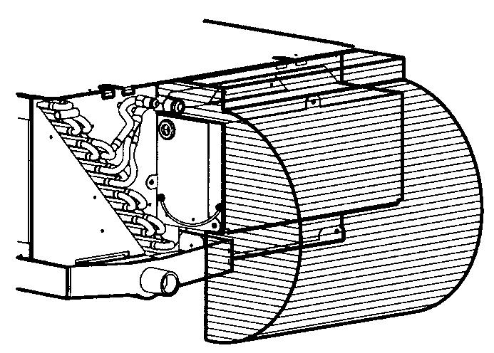
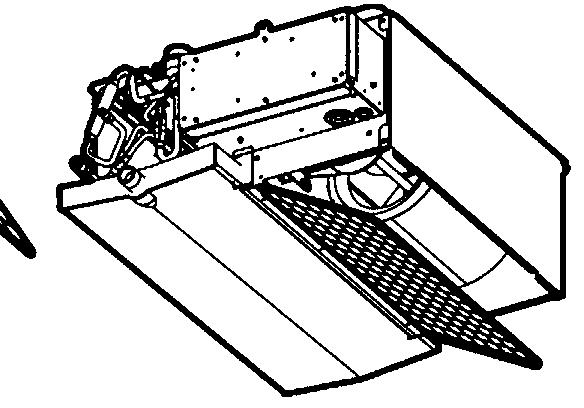
5 IMPORTANT INFORMATION REGARDING THE REFRIGERANT USED This product contains fluorinated greenhouse gases covered by the Kyoto Protocol. Refrigerant type: R0A GWP () value: 975 () GWP = global warming potential Periodical inspections for refrigerant leaks may be required depending on European or local legislation. Please contact your local dealer for more information. SELECTING INSTALLATION SITE (See figure ). Select an installation site where the following conditions are fulfilled and that meets your customer's approval. The units are designed for ceiling concealed installation with an air discharge duct of 500 mm. (See figure ) Where optimum air distribution can be ensured. Where nothing blocks air passage. Where condensate water can be properly drained. Where the false ceiling is not noticeably on an incline. Where sufficient clearance for maintenance and service can be ensured. Where piping between indoor and outdoor units is possible within the allowable limit. (Refer to the installation manual of the outdoor unit.) Make sure that no piping is passing through the hatched area (figure 6). Condensation can drip on the switch box and pipes can prevent you from opening the switch box smoothly. This is a class A product. In a domestic environment this product may cause radio interference in which case the user may be required to take adequate measures. Keep indoor unit, outdoor unit, power supply wiring and transmission wiring at least meter away from televisions and radios. This is to prevent image interference and noise in those electrical appliances. (Noise may be generated depending on the conditions under which the electric wave is generated, even if meter is kept.). Use suspension bolts for installation. Check whether the ceiling is strong enough to support the weight of the indoor unit. If there is a risk, reinforce the ceiling before installing the unit. (See figure ) Service space 00 Drain pipe Power supply wiring port Transmission wiring port 5 Gas pipe 6 Liquid pipe 7 Switch box 8 Switch box cover 9 Screw for opening the switch box cover 0 Suspension bolt pitch (x) Suspension bolt pitch distance PREPARATIONS BEFORE INSTALLATION. Relation of ceiling opening to unit and suspension bolt position. (See figure ) NOTE For other installation than standard installation, contact your Daikin dealer for details.. Make the wall hole to the outdoor side for the electric wiring, the refrigerant and drain piping. The hole must slope down toward the outdoor side. The hole size must be just as large as to hold the protective pipe (Ø7-8 cm) (field supply). Use a wall hole cover (field supply) to hide the wall hole as much as possible. Protective pipe (field supply) Wall hole cover (field supply). The fan speed for this indoor unit is preset to provide standard external static pressure. If higher or lower external static pressure is required, reset the external static pressure by changing the initial setting from the remote controller.. Install the suspension bolts. (See figure ) (Use M0 size bolt for the suspension bolt.) Use anchors for existing ceilings, and a sunken insert, sunken anchors or other field supplied parts for new ceilings to reinforce the ceiling in order to bear the weight of the unit. Anchor Ceiling slab Long nut or turn-buckle Suspension bolt NOTE All the above parts are field supplied. INDOOR UNIT INSTALLATION When installing optional accessories, read also the installation manual of the optional accessories. Depending on the field conditions, it may be easier to install optional accessories before the indoor unit is installed.. Install the indoor unit temporarily. Attach the hanger bracket to the suspension bolt. Be sure to fix it securely by using a nut and washer from the upper and lower sides of the hanger bracket. (See figure ) Field procurement Washer for hanger bracket Tighten (double nut). Check if the unit is horizontally levelled. Do not install the unit tilted. Check if the unit is levelled at all four corners with a water level or a water-filled vinyl tube as shown in figure 9. Water level Vinyl tube. Tighten the upper nut. REFRIGERANT PIPING WORK Ø7-8 cm For refrigerant piping of outdoor unit, refer to the installation manual supplied with the outdoor unit. Before rigging tubes, check which type of refrigerant is used. All field piping must be provided by a licensed refrigeration technician and must comply with the relevant local and national codes. Use a pipe cutter and flare suitable for R0A. Apply ether oil or ester oil around the flare portions before connecting. FXDQ0+5M8VB PW508-C
6 To prevent dust, moisture or other foreign matter from infiltrating the tube, either pinch the end, or cover it with tape. The outdoor unit is charged with refrigerant. Be sure to use both a spanner and torque wrench together when connecting or disconnecting pipes to/from the unit. Torque wrench Spanner Piping union Flare nut Refer to Table for the dimensions of flare nut spaces and the appropriate tightening torque. (Overtightening may damage the flare and cause leaks.) When connecting the flare nut, coat the flare both inside and outside with ether oil or ester oil and initially tighten by hand or turns before tightening firmly. Coat here with ether oil or ester oil DRAIN PIPING WORK Rig the drain piping as shown in figure and take measures against condensation. Improperly rigged piping could lead to leaks and eventually wet furniture and belongings. Hanging bar -.5 m. Install the drain pipes. Keep piping as short as possible and slope it downwards so that air may not remain trapped inside the pipe. Keep pipe size equal to or greater than that of the connecting pipe (Vinyl pipe of 5 mm nominal diameter and mm outer diameter). Do not use a trap in the drain piping and never put the end of the hose into water. (See figure ) If you extend the drain hose, always insulate it up to the outdoor side with polyethylene foam insulation material (field supply). Drain hose fixed to the indoor unit Indoor side extension drain hose Check the pipe connector for gas leaks. Be sure to insulate the gas pipe and the liquid pipe separately with polyethylene foam insulation material (thermal conductivity = 0.0~0.05 kw/mk). Inside diameter Wall thickness Gas pipe insulation 5 mm 8 0 mm Liquid pipe insulation 8 0 mm 7 0 mm Wall Polyethylene foam To ensure a downward slope of :00, install hanging bars every to.5 m. If unifying multiple drain pipes, install the pipes as shown. NOTE For the gas pipe, use a polyethylene foam resistant to a temperature of 0 C. When inserting the refrigerant piping in the wall hole, take care not to let dust or moisture come into the piping. Protect the pipes with a cap or seal the pipe end completely with tape.. After piping work is finished, check if drainage flows smoothly. Make sure that the drain hose is firmly connected. Pour some water into the drain pan to check if the water flows smoothly. When electric wiring work is finished Check drainage flow during COOL running, explained in chapter "Test operation". When electric wiring work is not finished Table Pipe gauge Tightening torque Flare dimension A (mm) Flare shape Remove the switch box lid and connect the power supply and remote controller to the terminals. (See figure 7) Power supply wiring Wiring port Ø6..~7. N m (~76 kgf cm) 8.7~9. 90 ± A 5 ± Indoor PC board Power supply terminal board Ø.7 9.5~60. N m (50~66 kgf cm) 6.~6.6 R=0.~0.8 5 Transmission wiring between units 6 Remote controller wiring 7 Terminal board for unit transmission wiring 8 Electric parts box lid 9 Wiring diagram 0 Electric parts box FXDQ0+5M8VB PW508-C
7 Next, press the inspection/test operation button on the remote controller. The unit will engage the test operation mode. Press the operation mode selector button until selecting fan operation. Then, press the on/off button. The indoor unit fan and drain pump will start up. Check that the water has drained from the unit. Press TEST TEST to go back to the first mode. WIRING EXAMPLE AND HOW TO SET THE REMOTE CONTROLLER How to connect wiring Open the switch box cover, as shown in figure 7, to make connections. ELECTRIC WIRING WORK General instructions All field supplied parts and materials and electric works must conform to local codes. Use copper wire only. Follow the "Wiring diagram" attached to the switch box cover to wire the outdoor unit, indoor units and the remote controller. For details on hooking up the remote controller, refer to the "Installation manual of the remote controller". All wiring must be performed by an authorized electrician. A circuit breaker capable of shutting down power supply to the entire system must be installed. This system consists of multiple indoor units. Mark each indoor unit as unit A, unit B..., and be sure the terminal board wiring to the outdoor unit and BS unit are properly matched. If wiring and piping between the outdoor unit and an indoor unit are mismatched, the system may cause a malfunction. Electrical characteristics Model Hz Volts Voltage range FXDQ min. 98 max. 6 MCA: Min. circuit Amps (A) MFA: Max. Fuse Amps (A) KW: Fan Motor Rated Output (kw) FLA: Full Load Amps (A) Power supply Fan motor Model MCA MFA KW FLA FXDQ A NOTE For details, refer to "Electrical data". Precautions. Observe the notes mentioned below when wiring to the power supply terminal board. Do not connect wires of different gauge to the same power supply terminal. (Looseness in the connection may cause overheating.) When connecting wires of the same gauge, connect them according to the figure.. Keep total current of crossover wiring between indoor units less than A. Branch the line outside the terminal board of the unit in accordance with electrical equipment standards, when using two power wiring of a gauge greater than mm (Ø.6). The branch must be sheathed in order to provide an equal or greater degree of insulation as power supply wiring itself.. Do not connect wires of different gauge to the same grounding terminal. Looseness in the connection may deteriorate the protection.. Remote controller cords and wires connecting the units should be located at least 50 mm away from power supply wiring. Not following this guideline may result in malfunction due to electrical noise. 5. For the remote controller wiring, refer to the "Installation manual of the remote controller" supplied with the remote controller. 6. Never connect the power supply wiring to the terminal board for transmission wiring. This mistake could damage the entire system. 7. Use only specified wires and tightly connect wires to the terminals. Be careful that wires do not place external stress on the terminals. Keep wiring in neat order so that they do not obstruct other equipment such as popping open the service cover. Make sure the cover closes tight. Incomplete connections could result in overheating, and in the worse case, electric shock or fire. Specifications for field supplied fuses and wire Power supply wiring Model Field fuses Wire Size FXDQ0+5 6 A H05VV-UG Local codes Model Wire Size FXDQ0+5 Sheathed wire () mm NOTE For details, refer to the chapter "Wiring example". Allowable length of transmission wiring between indoor and outdoor units, and between the indoor unit and the remote controller is as follows: Outdoor unit - indoor unit: max. 000 m (total wiring length: 000 m) Indoor unit - remote controller: max 500 m WIRING EXAMPLE Fit the power supply wiring of each unit with a switch and fuse as shown in figure 6. Power supply Main switch Power supply wiring Transmission wiring 5 Switch 6 Fuse 7 BS unit REYQ only 8 Indoor unit 9 Remote controller FXDQ0+5M8VB PW508-C
8 Complete system example ( systems) When using remote controller for indoor unit (Normal operation) (See figure 8) For group control or use with remote controllers (See figure 0) When including BS unit (See figure ) Outdoor unit Indoor unit Remote controller (Optional accessories) Most downstream indoor unit 5 For use with remote controllers 6 BS unit NOTE Precautions. A single switch can be used to supply power to units on the same system. However, branch switches and branch circuit breakers must be selected carefully.. For a group control remote controller, choose the remote controller that suits the indoor unit which has the most functions.. Do not ground the equipment on gas pipes, water pipes, lightning rods or crossground with telephones. Improper grounding could result in electric shock. FIELD SETTING It is not necessary to designate indoor unit address when using group control. The address is automatically set when the power is activated. Field setting must be made on the remote controller in function of the installation condition. Setting can be made by changing the "Mode number", "First code No." and "Second code No.". For setting and operation, refer to the "Field settings" in the installation manual of the remote controller. Summary of field settings Mode No. (Note ) 0 (0) () () 5 (5) Note : First code No. 0 Description of setting Filter contamination - Heavy/Light = Setting to define time between filter cleaning display indications. (When contamination is high, setting can be changed to half the time inbetween filter cleaning display indications.) Ultra-longlife filter Long-life filter Standard filter Thermostat sensor selection 6 0 Light Second code No. (Note ) ±0,000 hrs. Heavy ±5,000 hrs. ±,500 hrs. ±,50 hrs. ±00 hrs. ±00 hrs. Use both the unit sensor (or remote sensor if installed) AND the remote controller sensor. (See note 5+6) Use unit sensor only (or remote sensor if installed). (See note 5+6) Use remote controller sensor only. (See note 5+6) Setting for display of time between filter cleaning display Display Do not display indications Thermostat sensor in group control Output signal X-X of the optional KRPB PCB kit ON/OFF input from outside (T/T input) = Setting when forced ON/OFF is to be operated from outside. Fan setting during thermostat OFF at heating operation Differential automatic changeover Use unit sensor only (or remote sensor if installed). (See note 6) Use both the unit senor (or remote sensor if installed) AND the remote controller sensor. (See note +5+6) Thermostat-on + compressor run Operation Malfunction Forced OFF LL ON/OFF operation Set speed 0 C C C OFF (See note ) 5 Auto-restart after power failure Disabled Enabled 9 Fixed cool/heat master Disabled Enabled 6 Setting the external static pressure (To be set in function of the connected duct resistance) Drain pump operation + humidifier interlock Normal High static pressure Low static pressure Equipped Not equipped C (See note 7) Setting is carried out in the group mode, however, if the mode number inside parentheses is selected, indoor units can also be set individually. Note : Factory settings of the Second code No. are marked in grey backgrounds. Note : Only use in combination with optional remote sensor or when setting 0--0 is used. Note : If group control is selected and remocon sensor is to be used, then set & Note 5 : If setting or 0--0 or 0--0 are set at the same time, then setting 0--0, 0--0 or 0--0 have priority. Note 6 : Note 7 : If setting or 0--0 or 0--0 are set at the same time, then setting for group connection, has priority and for individual connection, 0--0, 0--0 or 0--0 have priority. More settings for Differential automatic change over temperatures are: Second code No. 05 C 06 5 C 07 6 C 08 7 C Control by Remote Controllers (Controlling indoor unit by remote controllers) When using remote controllers, one must be set to "MAIN" and the other to "SUB". 5 FXDQ0+5M8VB PW508-C
 (The remote controller PC board is attached to the upper part of the remote controller.). Turn the main/sub changeover switch on one of the two remote controller PC boards to \"S\".")
9 Main/sub changeover. Insert a wedge-head screwdriver into the recess between the upper and lower part of the remote controller and, working from the positions, pry off the upper part. (See figure ) (The remote controller PC board is attached to the upper part of the remote controller.). Turn the main/sub changeover switch on one of the two remote controller PC boards to "S". (See figure 5) (Leave the switch of the other remote controller set to "M".) Remote controller PC board Factory setting Only one remote controller needs to be changed Computerised control (forced off and on/off operation). Wire specifications and how to perform wiring. Connect input from outside to terminals T and T of the terminal board (remote controller to transmission wiring). TEST OPERATION Refer to the installation manual of the outdoor unit. The operation lamp of the remote controller will flash when an error occurs. Check the error code on the liquid crystal display to identify the trouble. An explanation of error codes and the corresponding trouble is provided on "Caution for servicing" sticker included in the accessory bag. SPECIAL FEATURES Air suction direction This feature allows the user to choose the air suction direction. By switching the plate from bottom to rear, the air suction direction can be changed from the rear to the bottom side. Wire specification Gauge mm Length External terminal Sheathed vinyl cord or cable ( wire) Max. 00 m Contact that can ensure the minimum applicable load of 5 V DC, 0 ma See figure. Input A. Actuation The following table explains "forced off" and "on/off operations" in response to input A. Drain pan outlet The customer has the possibility to select either right or left sided water drain outlet. Forced off Input "on" stops operation Input "off" enables control on/off operation input off on: turns on the unit (impossible by remote controllers) input on off: turns off the unit by remote controller. How to select forced off and on/off operation Turn the power on and then use the remote controller to select operation. Set the remote controller to the field set mode. For details, refer to the chapter "How to set in the field", in the remote controller manual. When in the field set mode, select mode No., then set the first code (switch) No. to "". Then set second code (position) No. to "0" for forced off and to "0" for on/off operation. (forced off at factory set.) (See figure 7) Second code No. Mode No. First code No. Field set mode Centralized control For centralized control, it is necessary to designate the group No. For details, refer to the manual of each optional controller for centralized control. Air inlet Air outlet Remote controller FXDQ0+5M8VB PW508-C 6
10 MAINTENANCE Important ONLY A QUALIFIED SERVICE PERSON IS ALLOWED TO PERFORM MAINTENANCE. BEFORE OBTAINING ACCESS TO TERMINAL DEVICES, ALL POWER SUPPLY CIRCUITS MUST BE INTERRUPTED. DO NOT USE WATER OR AIR OF 50 C OR HIGHER FOR CLEANING AIR FILTERS AND OUTSIDE PANELS. DISPOSAL REQUIREMENTS Dismantling of the unit, treatment of the refrigerant, of oil and of other parts must be done in accordance with relevant local and national legislation. How to clean the air filter Clean the air filter when the display shows " " (TIME TO CLEAN AIR FILTER). Increase the frequency of cleaning if the unit is installed in a room where the air is extremely contaminated. (As a yardstick for yourself, consider cleaning the filter once a half year.) If dirt becomes impossible to clean, change the air filter. (Air filter for exchange is optional.) NOTE Do not operate the air conditioner without filters, this to avoid dust accummulation inside the unit.. Removing the air filter Rear suction (See figure 5a): Pull the bottom side of the air filter backwards, over the bends. Bottom suction (See figure 5b): Pull the filter over the two bends situated at the backside of the unit.. Cleaning the air filter Remove dust from the air filter using a vacuum cleaner and gently rinse them in cool water. Do not use detergent or hot water to avoid filter shrinking or deformation. After cleaning dry them in the shade.. Replacing the air filter Rear suction (See figure 5a): Hook the filter behind the flap situated at the top of the unit and push the other side gently over the bends. Bottom suction (See figure 5b): Hook the filter behind the flap situated at the middle of the unit and push the other side gently over the bends.. After turning power on, press the FILTER SIGN RESET button. The "TIME TO CLEAN AIR FILTER" display disappears. (For details, refer to the operation manual of the outdoor unit.) NOTE Do not remove the air filter except when cleaning. Unnecessary handling may damage the filter. Do not use gasoline, benzene, thinner, polishing powder nor liquid insecticide. It may cause discolouring or warping. Do not let the indoor unit get wet. It may cause electric shock or fire. 7 FXDQ0+5M8VB PW508-C
11 WIRING DIAGRAM : FIELD WIRING BLK : BLACK : TERMINAL BLU : BLUE : CONNECTOR ORG : ORANGE : WIRE CLAMP PNK : PINK : PROTECTIVE EARTH (SCREW) RED : RED WHT : WHITE YLW : YELLOW AP...PRINTED CIRCUIT BOARD CR...CAPACITOR (FAN) FU...FUSE (50 V/0 A) FU...FIELD FUSE HAP...LIGHT EMITTING DIODE (SERVICE MONITOR - GREEN) MF...MOTOR (FAN) QE...EARTH LEAK DETECTOR RT...THERMISTOR (AIR) RT,RT...THERMISTOR (REFRIGERANT) RyF-...MAGNETIC RELAY (FAN) XM...TERMINAL STRIP (POWER) XM...TERMINAL STRIP (CONTROL) TR...TRANSFORMER (0-0 V/ V) YE...ELECTRONIC EXPANSION CIRCUIT OPTIONAL PARTS JEH...ELECTRIC HEATER KR...MAGNETIC RELAY (JEH) ADAPTOR FOR WIRING RyC,RyF...MAGNETIC RELAY RyH...MAGNETIC RELAY (JEH) FU,FU...FUSE (50 V/5 A) XA,XA...CONNECTOR (WIRING ADAPTOR) XM...TERMINAL STRIP CONNECTOR FOR OPTIONAL PARTS X6A...CONNECTOR (WIRING ADAPTOR) X8A...CONNECTOR (WIRING ADAPTOR FOR ELECTRICAL APPENDICES) RECEIVER/DISPLAY UNIT : WIRED REMOTE CONTROLLER : SWITCH BOX : TRANSMISSION WIRING : INPUT FROM OUTSIDE : CENTRAL REMOTE CONTROLLER : NOTE. WHEN USING THE CENTRAL REMOTE CONTROLLER, SEE MANUAL FOR CONNECTION TO THE UNIT.. XA IS CONNECTED WHEN THE CENTRAL REMOTE CONTROLLER IS USED.. WHEN CONNECTING THE INPUT WIRES FROM OUTSIDE, FORCED OFF OR ON/OFF CONTROL OPERATION CAN BE SELECTED BY THE REMOTE CONTROLLER. SEE INSTALLATION MANUAL FOR MORE DETAILS. FXDQ0+5M8VB PW508-C 8
12 NOTES


13 8 9 Control box IN/D OUT/D F F F F L N L N L N L N LN P P F F T T LN P P F F T T LN P P F F T T LN P P F F T T P P P P P P P P L N Control box IN/D OUT/D F F F F LN P P F F T T LN P P F F T T LN P P F F T T LN P P F F T T P P 5 P P P P L N Control box IN/D OUT/D F F F F Control box OUT/D IN/D F F F F S M LN P P F F T T F T T FORCED OFF S M P P SETTING
14 Zandvoordestraat 00, B-800 Oostende, Belgium PW508-C
USER'S MANUAL FAN MOTOR DRIVER FMD-02
 USER'S MANUAL FAN MOTOR DRIVER FMD-02 IMPORTANT NOTE: Read this manual carefully before installing or operating your new air conditioning unit. Make sure to save this manual for future reference. FMD Module
ADDRESS CONVERSION TABLE FOR MANUAL SETTING
 - (06-57) - ADDRESS CVERSI TABLE FOR MANUAL SETTING In the case of a multiple refrigerant system, each refrigerant system should be set an exclusive refrigerant. Conversion table of refrigerant and rotary
GUIDELINES FOR CONNECTION TO FTP SERVER TO TRANSFER PRINTING DATA
 GUIDELINES FOR CONNECTION TO FTP SERVER TO TRANSFER PRINTING DATA What is an FTP client and how to use it? FTP (File transport protocol) - A protocol used to transfer your printing data files to the MAFRAPRINT
 11.12. 100 ΕΙΣΟΔΟΣ = E / ENTRANCE = E = = 1174 550 ΤΥΠΟΠΟΙΗΜΕΝΟ ΚΥ = 2000 (ΕΠΙΛΟΓΗ: 2100) / CH STANDARD = 2000 (OPTIONAL: 2100) 243 50 ΚΥ/CH + 293 ΚΥ/CH +103 100 ΚΥ /CH 6 11 6 20 100 0,25 ΚΑ (CO) + 45
2N LiftIP. IO Extender. Communicator for Lifts. Version
 2N LiftIP Communicator for Lifts IO Extender Version 2.4.0 www.2n.cz Description The IO extender helps you extend 2N LiftIP with 1 input and 2 outputs. The purpose of the input is to cancel the rescue
UŽIVATELSKÁ PŘÍRUČKA
 UŽIVATELSKÁ PŘÍRUČKA Plni víry a naděje míříme kupředu. S odhodláním zlepšujeme své dovednosti. Zapomeňte na zklamání, ale nikoli na svůj nevyužitý potenciál. Touha překonat sám sebe a dosáhnout hranice
USER'S MANUAL FAN MOTOR DRIVER FMD-01, FMD-03
 USER'S MANUAL FAN MOTOR DRIVER FMD-01, FMD-03 IMPORTANT NOTE: Read this manual carefully before installing or operating your new air conditioning unit. Make sure to save this manual for future reference.
ROLZ-2. Portable AV/Conference Center. Assembly Instructions
 1 ROLZ-2 Portable AV/Conference Center Assembly Instructions Rolz-2 Portable AV/Conference Center Part Drawing Description Qty Part Drawing Description Qty Hardware List A 1 ½ Flat Head Screw 2 EA P-1
obal manuálu, asi něco podobného jako u LC 100 asi by to chtělo lepší obrázek!!! FYTOSCOPE FS130 Instruction Guide
 obal manuálu, asi něco podobného jako u LC 100 asi by to chtělo lepší obrázek!!! FYTOSCOPE FS130 Instruction Guide možná tohle trochu zmenšit a dát sem i to varování LED RADIATION co je na další straně
2N Voice Alarm Station
 2N Voice Alarm Station 2N Lift1 Installation Manual Version 1.0.0 www.2n.cz EN Voice Alarm Station Description The 2N Voice Alarm Station extends the 2N Lift1/ 2N SingleTalk with an audio unit installed
Uživatelská příručka. USB Charger UCH20
 Uživatelská příručka USB Charger UCH20 Obsah Úvod...3 USB Charger popis... 3 Používání nabíječky USB... 4 Nabíjení zařízení... 4 Právní informace... 5 Declaration of Conformity...6 2 Úvod USB Charger popis
Size / Světlost : DN 1/4 to 4 / DN 1/4 až 4
 Size / Světlost : 1/4 to 4 / 1/4 až 4 Ends / Konce : Threaded BSP / Závitové BSP Min. Temperature / Minimální teplota : -20 C Max. Temperature / Maximální teplota : +180 C Max. Pressure / Maximální tlak
Název společnosti: VPK, s.r.o. Vypracováno kým: Ing. Michal Troščak Telefon: Datum:
 Pozice Počet Popis 1 SCALA2 3-45 A Datum: 2.7.217 Výrobní č.: 98562862 Grundfos SCALA2 is a fully integrated, self-priming, compact waterworks for pressure boosting in domestic applications. SCALA2 incorporates
DATA SHEET. BC516 PNP Darlington transistor. technický list DISCRETE SEMICONDUCTORS Apr 23. Product specification Supersedes data of 1997 Apr 16
 zákaznická linka: 840 50 60 70 DISCRETE SEMICONDUCTORS DATA SHEET book, halfpage M3D186 Supersedes data of 1997 Apr 16 1999 Apr 23 str 1 Dodavatel: GM electronic, spol. s r.o., Křižíkova 77, 186 00 Praha
PC/104, PC/104-Plus. 196 ept GmbH I Tel. +49 (0) / I Fax +49 (0) / I I
 / I Fax +49 (0) / I I") E L E C T R O N I C C O N N E C T O R S 196 ept GmbH I Tel. +49 (0) 88 61 / 25 01 0 I Fax +49 (0) 88 61 / 55 07 I E-Mail sales@ept.de I www.ept.de Contents Introduction 198 Overview 199 The Standard 200
E L E C T R O N I C C O N N E C T O R S 196 ept GmbH I Tel. +49 (0) 88 61 / 25 01 0 I Fax +49 (0) 88 61 / 55 07 I E-Mail sales@ept.de I www.ept.de Contents Introduction 198 Overview 199 The Standard 200
INDUCTION HEATING CAPACITORS KONDENZÁTORY PRO INDUKČNÍ OHŘEV
 INDUCTION HEATING CAPACITORS KONDENZÁTORY PRO INDUKČNÍ OHŘEV SCA - 2012-1 CONTENTS OBSAH 03 General technical information Obecné technické informace 04 Medium Frequency Capacitors - water cooled, up to
Hi-Res Audio/DNC Headset MDR-NC750
 Uživatelská příručka Hi-Res Audio/DNC Headset MDR-NC750 Obsah Začínáme...3 Úvod...3 Přehled... 3 Základy práce...4 Nošení náhlavní soupravy...4 Připojení náhlavní soupravy k vašemu zařízení... 4 Nastavení
Název společnosti: VPK, s.r.o. Vypracováno kým: Ing. Michal Troščak Telefon: Datum:
 Počet 1 SCALA2 3-45 A Datum: 2.7.217 Výrobní č.: 98562862 Grundfos SCALA2 is a fully integrated, self-priming, compact waterworks for pressure boosting in domestic applications. SCALA2 incorporates integrated
User manual SŘHV Online WEB interface for CUSTOMERS June 2017 version 14 VÍTKOVICE STEEL, a.s. vitkovicesteel.com
 1/ 11 User manual SŘHV Online WEB interface for CUSTOMERS June 2017 version 14 2/ 11 Contents 1. MINIMUM SYSTEM REQUIREMENTS... 3 2. SŘHV ON-LINE WEB INTERFACE... 4 3. LOGGING INTO SŘHV... 4 4. CONTRACT
GENERAL INFORMATION RUČNÍ POHON MANUAL DRIVE MECHANISM
 KATALOG CATALOGUE RUČNÍ POHONY PRO VENKOVNÍ PŘÍSTROJE, MONTÁŽ NA BETONOVÉ SLOUPY MANUAL DRIVE MECHANISM FOR THE ACTUATION OF OUTDOOR TYPE SWITCHING DEVICES MOUNTED ON THE CONCRETE POLES TYP RPV ISO 9001:2009
INSTALLATION MANUAL. Split System air conditioners FFQ25B8V1B FFQ35B8V1B FFQ50B8V1B FFQ60B8V1B
 INSTALLATION MANUAL FFQB8VB FFQB8VB FFQ0B8VB FFQ60B8VB 6 7 8 9 0 x x 8x x x x x x x x x 0~00 6 7 8 00 00* 00* 00 700 8~660 7 9 6 7 8 00* 00* 8~660 700 9 8~660* 8 80 7 00* 00* 0 0 6 7 9 0 6 0 00 00 00 -.
WL-5480USB. Quick Setup Guide
 Quick Setup Guide 1 Czech 7 Install Utility Software Note1: Before installing the utility software, DO NOT inserts the into your computer. If the adapter is inserted already, Windows will detect the adapter
INSTALLATION AND OPERATION MANUAL
 INSTALLATION AND OPERATION MANUAL System air conditioners FXSQ0P7VEB FXSQP7VEB FXSQP7VEB FXSQ0P7VEB FXSQ0P7VEB FXSQP7VEB FXSQ80P7VEB FXSQ00P7VEB FXSQP7VEB 7 00 A B 0 700 a b c < 00 80 80 7 80 a b c 7a
Izolační manipulační tyče typ IMT IMT Type Insulated Handling Rod
 KATALOG CATALOGUE 024/09/2011 IZOLAČNÍ MANIPULAČNÍ TYČ INSULATED HANDLING ROD TYP IMT KOVOVÁ MANIPULAČNÍ TYČ METALLIC HANDLING ROD TYP KMT ISO 9001:2009 ISO 14001:2005 Izolační manipulační tyče typ IMT
AUTOMATICKÝ DÁVKOVAČ Harvia. Návod na instalaci a použití instructions for installation and Use
 AUTOMATICKÝ DÁVKOVAČ Harvia Návod na instalaci a použití instructions for installation and Use 15122011 CZ EN 1. OBECNÉ INFORMACE 1. GENEraL Účelem Harvia automatického dávkovače je aplikovat vodu a směs
2N LiftIP. Voice Alarm Station. Communicator for Lifts. Version
 2N LiftIP Communicator for Lifts Voice Alarm Station Version 2.4.0 www.2n.cz Description The 2N Voice Alarm Station is a switch that helps you extend 2N LiftIP with one or more audio units installed on
ELEKTROMOTORY SÉRIE CHT CHT ELECTRIC MOTORS
 ELEKTROMOTORY SÉRIE CHT CHT ELECTRIC MOTORS ÚVOD CHT série elektromotor byla vyvinuta pro p ipojení na p evodovky a z tohoto d vodu mají veškeré mechanické a elektrické charakteristiky p izp sobeny práv
INSTALLATION MANUAL PD 0027.01
 INSTALLATION MANUAL PD 0027.01 OUTDOOR MOTOR DRIVE FOR MV DISCONNECTORS ISO 9001:2009 ISO 14001:2005 OHSAS 18001:2008 TYPE SUP a) STORAGE / SKLADOVÁNÍ The packed devices on wooden pallet it is not allowed
Quick Start Guide. Clear. Rychlý průvodce nastavením
 CZ EN Quick Start Guide Clear Rychlý průvodce nastavením Measurement Měření Před Fully prvním charge použitím the blood plně pressure dobijte monitor baterii before přístroje. first use. 1 Rest your bare
KATALÓGOVÉ LISTY SEZ-KD25-71VAQ. Single split. Inštalačné dáta
 KTLÓGOVÉ LISTY Inštalačné dáta Single split SEZ-KD25-7VQ Kutlíkova 7, Budova TEHNOPOL, 852 Bratislava Telefón: +42 7 845 E-mail: info@dobraklima.sk SEZ SEZ-KD25 7VQ SUZ-K 7V SUZ-K25 35V Kanálové jednotky
SPECIFICATION FOR ALDER LED
 SPECIFICATION FOR ALDER LED MODEL:AS-D75xxyy-C2LZ-H1-E 1 / 13 Absolute Maximum Ratings (Ta = 25 C) Parameter Symbol Absolute maximum Rating Unit Peak Forward Current I FP 500 ma Forward Current(DC) IF
MSZ-SF15VA MSZ-SF20VA
 Multisplit Inverter / chlazení nebo topení Výhody K zajištění optimálního proudění vzduchu je možné nastavit jeden z pěti stupňů otáček ventilátoru. Pro velmi rychlé dosažení požadovaného mikroklima slouží
TECHNICKÝ LIST řada mechanických odvaděčů kondenzátu AUTODRAIN TECHNICAL DATA SHEET for mechanical autodrain equipment AUTODRAIN
 Popis: Nádoba s mechanickým plovákem k odstraňování pevných nečistot, vody, aerosolů, uhlovodíků, prachu oddělených separátory KING AIR se systémem stlačeného vzduchu. Rozdělení dle využití instalace:
Nástěnné jednotky Split Inverter / chlazení nebo topení
 Nástěnné jednotky Split Inverter / chlazení nebo topení Výhody Technologie replace: bez problémů můžete použít stávající R22 vedení chladiva. DC inverterová technologie a ekologické chladivo R410A zajišťuje
INSTALLATION MANUAL. Split series room air conditioners Multi system room air conditioners FDBQ25B8V1
 INSTALLATION MANUAL 1 1 2 3 2 3 6 5 4 4 5 6 CE - ATITIKTIES-DEKLARACIJA CE - ATBILSTĪBAS-DEKLARĀCIJA CE - VYHLÁSENIE-ZHODY CE - UYUMLULUK-BİLDİRİSİ CE - IZJAVA O SKLADNOSTI CE - VASTAVUSDEKLARATSIOON CE
SERVISNÍ MANUÁL PEGAS 250 E CEL OVO SERVICE MANUAL PEGAS 250 E CEL OVO
 MG136-1 PEGAS 250 E CEL OVO SERVICE MANUAL page 1 SERVISNÍ MANUÁL PEGAS 250 E CEL OVO SERVICE MANUAL PEGAS 250 E CEL OVO 1. VAROVÁNÍ WARNING UPOZORNĚNÍ Pouze osoba splňující kvalifikaci danou zákonem je
DVM CHILLER. Installation manual. Module control MCM-A00N
 Installation manual Module control MCMA00N Thank you for purchasing this Samsung air conditioner. Before operating this unit, please read this installation manual carefully and retain it for future reference.
VENTIL ZPĚTNÝ JEDNODÍLNÝ ZÁVITOVÝ Teplota max.-20 C/150 C TYP C09.Z PN16 DN ¼ -4
 VENTIL ZPĚTNÝ JEDNODÍLNÝ ZÁVITOVÝ Teplota max.-20 C/150 C TYP C09.Z PN16 DN ¼ -4 Size / Světlost : DN 1/4" to 4" / DN 1/4" až 4" Ends / Konce : Female-Female BSP / Závitové, vnitřní-vnitřní závit BSP Min.
Gymnázium, Brno, Slovanské nám. 7 WORKBOOK. Mathematics. Teacher: Student:
 WORKBOOK Subject: Teacher: Student: Mathematics.... School year:../ Conic section The conic sections are the nondegenerate curves generated by the intersections of a plane with one or two nappes of a cone.
UPM3 Hybrid Návod na ovládání Čerpadlo UPM3 Hybrid 2-5 Instruction Manual UPM3 Hybrid Circulation Pump 6-9
 www.regulus.cz UPM3 Hybrid Návod na ovládání Čerpadlo UPM3 Hybrid 2-5 Instruction Manual UPM3 Hybrid Circulation Pump 6-9 CZ EN UPM3 Hybrid 1. Úvod V továrním nastavení čerpadla UPM3 Hybrid je profil PWM
Litosil - application
 Litosil - application The series of Litosil is primarily determined for cut polished floors. The cut polished floors are supplied by some specialized firms which are fitted with the appropriate technical
INSTALLATION AND OPERATION MANUAL
 INSTALLATION AND OPERATION MANUAL System air conditioners FXFQ0P8VEB FXFQP8VEB FXFQP8VEB FXFQ0P8VEB FXFQ0P8VEB FXFQP8VEB FXFQ80P8VEB FXFQ00P8VEB FXFQP8VEB 00 00 * * 90 0-00 7 00 mm ~. m 8 0~7 7 7 80 7
INSTALLATION AND OPERATION MANUAL
 INSTALLATION AND OPERATION MANUAL System air conditioners FXFQ0AVEB FXFQAVEB FXFQAVEB FXFQ0AVEB FXFQ0AVEB FXFQAVEB FXFQ80AVEB FXFQ00AVEB FXFQAVEB CE - ATITIKTIES-DEKLARACIJA CE - ATBILSTĪBAS-DEKLARĀCIJA
:= = := :=.. := := := := ρ := := α := π α = α = := = :=
 := = := :=.. := := := := ρ := := α := π α = α = := = := := α := α := = := α := := α = = ρ ρ := := := = := = := := := + + := + + := + := := := := + + := + + := + = = = :=.. := η := η := := π = :=.. :=,
Pokyny k použití. Model-300. Napájecí zdroj. Návod na obsluhu Operating Instructions. se systémem Aquacontrol Napájací zdroj
 Pokyny k použití Model-300 Návod na obsluhu Operating Instructions Napájecí zdroj se systémem Napájací zdroj so systémom Power Supply with System BK 0011900 / PC AQUACONTROL Kryt aquacontrol Kryt aquacontrol
FILTR ZÁVITOVÝ CELONEREZOVÝ Teplota max.-30 C/200 C TYP D PN16 DN1/4-2. Size / Světlost : DN 1/4 to 2 / DN 1/4 až 2 Ends / Konce :
 FILTR ZÁVITOVÝ CELONEREZOVÝ Teplota max.-30 C/200 C TYP D71 137 PN16 DN1/4-2 Size / Světlost : DN 1/4 to 2 / DN 1/4 až 2 Ends / Konce : Female Female BSP / Závitové BSP (vnitřní-vnitřní) Min. Temperature
Uživatelská příručka. Xperia P TV Dock DK21
 Uživatelská příručka Xperia P TV Dock DK21 Obsah Úvod...3 Přehled zadní strany stanice TV Dock...3 Začínáme...4 Správce LiveWare...4 Upgradování aplikace Správce LiveWare...4 Použití stanice TV Dock...5
INSTALLATION MANUAL. Split System air conditioners FDQ125C7VEB
 INSTALLATION MANUAL 7 00 A B 0 700 a b c < 00 80 80 7 80 a b c 7a 80 7c 0 (0~00) 0 A 7b 7a 80 0 0 A 7b 8 9 7c 0 8 9 00 mm ~. m 00 mm 0~7 A 0~ mm 0 CE - ATITIKTIES-DEKLARACIJA CE - ATBILSTĪBAS-DEKLARĀCIJA
1-AYKY. Instalační kabely s Al jádrem. Standard TP-KK-133/01, PNE 347659-3. Konstrukce. Použití. Vlastnosti. Installation cables with Al conductor
 Instalační kabely s Al jádrem Installation cables with Al conductor Standard TP-KK-133/01, PNE 347659-3 4 3 2 1 Konstrukce Construction 1 Hliníkové jádro Aluminium conductor 2 Izolace PVC 3 Výplňový obal
ROZM RY A P IPOJENÍ VÍ IVKY HYDROXEUR PEDI-JET
 DN FORMED Brno s.r.o. Hudcova 76a, 612 48 Brno Telefon: +420 541 321 095 Fax: +420 541 321 096 www.dnformed.cz dnformed@dnformed.cz len Asociace výrobc a dodavatel zdravotnických prost edk ROZM RY A P
2N Lift8 Audio unit machine room
 2N Lift8 Audio unit machine room Brief Manual Version 3.0.0 www.2n.cz The machine room audio unit is intended for installation in the machine room or as an intercom solution located in the reception.
20 ka / 1 s (dle typu cívky) přirozené
 přirozené") KATALOG CATALOGUE 051/03/2013 VÝKONOVÝ REAKTOR NN, NASTAVITELNÝ LOW VOLTAGE POWER REACTOR COIL, ADJUSTABLE pro napětí do 1000 V for voltages up to 1000V TYP LNN ISO 9001:2009 ISO 14001:2005 VŠEOBECNĚ Výkonový
KATALOG CATALOGUE 051/03/2013 VÝKONOVÝ REAKTOR NN, NASTAVITELNÝ LOW VOLTAGE POWER REACTOR COIL, ADJUSTABLE pro napětí do 1000 V for voltages up to 1000V TYP LNN ISO 9001:2009 ISO 14001:2005 VŠEOBECNĚ Výkonový
2N Lift8 Audio unit shaft
 2N Lift8 Audio unit shaft Brief Manual Version 3.0.0 www.2n.cz This audio unit is designed for installation on the lift shaft bottom or lift cabin roof, or wherever it is necessary to communicate (during
harvia griffin COLOUR LIGHT Control unit Ridici jednotka
 harvia griffin COLOUR LIGHT Control unit Ridici jednotka 13082008 These instructions for installation and use are intended for owners of colour light units and control units and for electricians responsible
TechoLED H A N D B O O K
 TechoLED HANDBOOK Světelné panely TechoLED Úvod TechoLED LED světelné zdroje jsou moderním a perspektivním zdrojem světla se širokými možnostmi použití. Umožňují plnohodnotnou náhradu žárovek, zářivkových
www.alu-sv.com BLATNÍKY A BEDNY NA NÁŘADÍ MUDGUARDS AND TOOLBOXES 5.1 5.2 5.3 5.4 5.5
 5.1 CZ LATNÍKY A EDNY NA NÁŘADÍ 5.1 latníky 5.2 edny na nářadí 5.3 Kanystry na vodu a schránky na hasící přístroje 5.4 Zakládací klíny 5.5 Držáky rezervy a navijáky EN 5.1 Mudguards 5.2 Toolboxes 5.3 Plastic
Mechanika Teplice, výrobní družstvo, závod Děčín TACHOGRAFY. Číslo Servisní Informace Mechanika: 5-2013
 Mechanika Teplice, výrobní družstvo, závod Děčín TACHOGRAFY Servisní Informace Datum vydání: 20.2.2013 Určeno pro : AMS, registrované subj.pro montáž st.měř. Na základě SI VDO č./datum: Není Mechanika
ZB5AV013 bílá signální hlavice Ø22 plná čočka pro integ. LED
 Characteristics bílá signální hlavice Ø22 plná čočka pro integ. LED Doplňky CAD celková šířka CAD celková výška CAD celková hloubka Hmotnost přístroje Označení skříně Označení el. složení Prostředí Stupeň
MA251 (cz_en) Operating instructions. MA251 (cz_en) Montážní návod. Krimpovací kleště PV-CZM... pro MC3, MC4 a MC4-EVO 2
 Operating instructions. MA251 (cz_en) Montážní návod. Krimpovací kleště PV-CZM... pro MC3, MC4 a MC4-EVO 2") MA251 (cz_en) Montážní návod Krimpovací kleště PV-CZM... pro MC3, MC4 a MC4-EVO 2 MA251 (cz_en) Operating instructions Crimping pliers PV-CZM... for MC3, MC4 and MC4-EVO 2 Obsah Bezpečnostní pokyny...2
MA251 (cz_en) Montážní návod Krimpovací kleště PV-CZM... pro MC3, MC4 a MC4-EVO 2 MA251 (cz_en) Operating instructions Crimping pliers PV-CZM... for MC3, MC4 and MC4-EVO 2 Obsah Bezpečnostní pokyny...2
INSTALLATION MANUAL. Split System air conditioners FBQ35C8VEB FBQ50C8VEB FBQ60C8VEB FBQ71C8VEB FBQ100C8VEB FBQ125C8VEB FBQ140C8VEB
 INSTALLATION MANUAL FBQC8VEB FBQ0C8VEB FBQ0C8VEB FBQ7C8VEB FBQ00C8VEB FBQC8VEB FBQ0C8VEB 7 00 A B 0 700 a b c < 00 80 80 7 80 a b c 7a 80 7c 0 (0~00) 0 A 7b 7a 80 0 0 A 7b 8 9 7c 0 8 9 00 mm ~. m 00 mm
INSTALAČNÍ NÁVOD OPERATING INSTRUCTION
 LED PRODISC II + LED PRODISC II MINI + LED PRODISC II MAXI INSTALAČNÍ NÁVOD OPERATING INSTRUCTION 4000944x 4000945x 4000940x 4000941x 4000946x 4000947x Prodisc II Mini Prodisc II Mini + MW senzor Prodisc
NÁVOD K OBSLUZE KOMBINOVANÝ OBUVNICKÝ STROJ BT - 202
 NÁVOD K OBSLUZE KOMBINOVANÝ OBUVNICKÝ STROJ BT - 202 OBSAH I. Hlavní součásti obuvnického stroje. II. Konstrukce III. Schéma elektrického zapojení IV. Instalace a uvedení do provozu V. Obsluha stroje VI.
Switch on the appropriate breaker and verify that the light is working properly.
 Package contents Name: MONA WALL PC970 wall light 445 Components included with unit: glass shade with light source, 1x metal light body, 1x wall mount, 3x terminal connectors, 2x hex screws M5, 1x hex
ZÓNOVÉ VENTILY S VRATNOU PRUŽINOU dvoucestné VZP 2XX 230 1P 001 třícestné VZP 3XX 230 1P 001
 Návod na instalaci a použití ZÓNOVÉ VENTILY S VRATNOU PRUŽINOU dvoucestné VZP 2XX 230 1P 001 třícestné VZP 3XX 230 1P 001 CZ verze 1.2 Popis: Zónové ventily s vratnou pružinou jsou určeny do hydraulických
TKGA3. Pera a klíny. Projekt "Podpora výuky v cizích jazycích na SPŠT"
 Projekt "Podpora výuky v cizích jazycích na SPŠT" Pera a klíny TKGA3 Tento projekt je spolufinancován Evropským sociálním fondem a státním rozpočtem ČR Pera a klíny Pera a klíny slouží k vytvoření rozbíratelného
ROLZ-2. Portable AV/Conference Center. Assembly Instructions
 1 ROLZ-2 Portable AV/Conference Center Assembly Instructions Rolz-2 Portable AV/Conference Center Part Drawing Description Qty Part Drawing Description Qty Hardware List A 1 ½ Flat Head Screw 2 EA P-1
VENTIL ZPĚTNÝ MEZIPŘÍRUBOVÝ PRUŽINOU - CELONEREZOVÝ Teplota max.-20 C/400 C TYP C09 PN 40 DN15-100
 VENTIL ZPĚTNÝ MEZIPŘÍRUBOVÝ PRUŽINOU - CELONEREZOVÝ Teplota max.-20 C/400 C TYP C09 PN 40 DN15-100 Size / Světlost : DN 15 to DN 100 / DN 15 až DN 100 Ends / Konce : Between flanges ISO PN 10/16/25/40
 If there is any inconsistency of weather forecast between Local Weather Station and this unit, the Local Weather Station's forecast should prevail. The trend pointer displayed on the LCD indicates the
Připojení internetového modulu econet300 Do regulátoru ecomax 810P3-L TOUCH.
 Připojení internetového modulu econet300 Do regulátoru ecomax 810P3-L TOUCH. Connection of econet300 internet module to ecomax 810P3-L TOUCH Controller. Prosím ověřte verzi softwaru vašeho modulu ecomax.
H2shop.cz. english česky
 návod Řídící elektronika HHO generátoru english česky Řídící jednotka slouží k uživatelskému nastavení impulzního proudu protékajícího HHO generátorem. Po nastavení jednotka sama udržuje konstantní nastavený
âistiã vzduchu / Air Cleaner MF 06, MF 08, MF 10 ada ASISTENT, velikost G 1/8, G 1/4, G 3/8 ASISTENT Series, G 1/8, G 1/4, G 3/8 Sizes
 âistiã vzduchu / Air Cleaner MF 06, MF 08, MF 10 ASISTENT Series, G 1/8, G 1/4, G 3/8 Sizes PouÏití pfiístroj na ãi tûní vzduchu a oddûlení vody (více neï 90 %) Use Device for air cleaning and water separation
SERVICE ADVISORY SA-5A
 V510 PROPELLER TYPE SERIES REPLACEMENT OF BLADE BEARING SEAL VRTULE TYPOVÉ ŘADY V510 VÝMĚNA TĚSNÍCÍ MANŽETY ULOŽENÍ LISTU 1. GENERAL A. This document provides disassembly and assembly procedure in the
HandiClamp. Single Band Repair Clamp Jednodílný Opravný Třmen INSTALLATION INSTRUCTIONS
 HandiClamp Single Band Repair Clamp Jednodílný Opravný Třmen INSTALLATION INSTRUCTIONS Montážní návod GB CZ Pioneers in pipe solutions INSTALLATION INSTRUCTIONS - English Single Band Repair Clamp 1 2 3
WORKSHEET 1: LINEAR EQUATION 1
 WORKSHEET 1: LINEAR EQUATION 1 1. Write down the arithmetical problem according the dictation: 2. Translate the English words, you can use a dictionary: equations to solve solve inverse operation variable
INSTALLATION MANUAL. Split System air conditioners FCQG35FVEB FCQG50FVEB FCQG60FVEB FCQG71FVEB FCQG100FVEB FCQG125FVEB FCQG140FVEB
 INSTALLATION MANUAL Split System air conditioners FCQGFVEB FCQG0FVEB FCQG0FVEB FCQG7FVEB FCQG00FVEB FCQGFVEB FCQG0FVEB FCQHG7FVEB FCQHG00FVEB FCQHGFVEB FCQHG0FVEB 00 00 * * 90 0-00 7 00 mm ~. m 8 0~7 7
Specifications AR5500
 Specifications AR5500 Easy Filter Plus Triangle Design Wi-Fi Control - Samsung SmartThings Model Name AR07NXWSAURNEU AR09NXWSAURNEU AR12NXWSAURNEU Power Supply Φ, #, V, Hz 1, 2, 220~240, 50 1, 2, 220~240,
jednodílný PN 40 závitový DN t.max. -20/+180 C
 100 Světlost / Size : DN 1/4 až 2 / DN 1/4 to 2 Konce / Ends : Závitové BSP / Threaded BSP Minimální teplota / Min. Temperature : -20 C Maximální teplota / Max. Temperature : +180 C Maximální tlak / Max.
1. ROZLIŠENÍ CS CU-05 a CS CU-05C
 - 1 Evidenční číslo: MG 004-01 Stroj / podskupina: Vodní chlazení Počet stran: 6 Počet příloh: Kopie č.: Vypracoval: Pavel Mastný Kontroloval: Holý Schválil: Holý Podpis: Podpis: Podpis: Datum: 9.2.2009
Tento materiál byl vytvořen v rámci projektu Operačního programu Vzdělávání pro konkurenceschopnost.
 Tento materiál byl vytvořen v rámci projektu Operačního programu Vzdělávání pro konkurenceschopnost. Projekt MŠMT ČR Číslo projektu Název projektu školy Klíčová aktivita III/2 EU PENÍZE ŠKOLÁM CZ.1.07/1.4.00/21.2146
DC circuits with a single source
 Název projektu: utomatizace výrobních procesů ve strojírenství a řemeslech egistrační číslo: Z..07/..0/0.008 Příjemce: SPŠ strojnická a SOŠ profesora Švejcara Plzeň, Klatovská 09 Tento projekt je spolufinancován
2N Lift8 Splitter. Brief Manual. Version
 2N Lift8 Splitter Brief Manual Version 2.0.0 www.2n.cz EN The splitter helps extend installations by interconnecting audio units in multiple lift shafts (audio units can be connected directly to the central
SERVICE MANUAL PEGAS 250 E CEL SERVISNÍ MANUÁL PEGAS 250 E CEL
 MG-011-05 PEGAS 250 E CEL SERVICE MANUAL page 1 SERVISNÍ MANUÁL PEGAS 250 E CEL SERVICE MANUAL PEGAS 250 E CEL 1. VAROVÁNÍ WARNING UPOZORNĚNÍ Pouze osoba splňující kvalifikaci danou zákonem je oprávněna
INSTALLATION MANUAL. System air conditioner. BS unit BSVQ100P9V1B BSVQ160P9V1B BSVQ250P9V1B
 INSTALLATION MANUAL System air conditioner READ THESE INSTRUCTIONS CAREFULLY BEFORE INSTALLATION. KEEP THIS MANUAL IN A HANDY PLACE FOR FUTURE REFERENCE. BSVQ100P9V1B BSVQ160P9V1B BSVQ250P9V1B 2 1 3 4
INSTALAČNÍ NÁVOD. R32 Split Series. Modely RXJ20M2V1B RXJ25M2V1B RXJ35M2V1B RXM20M2V1B RXM25M2V1B RXM35M2V1B ARXM25M2V1B ARXM35M2V1B
 INSTALAČNÍ NÁVOD R32 Split Series Modely RXJ20M2V1B RXJ25M2V1B RXJ35M2V1B RXM20M2V1B RXM25M2V1B RXM35M2V1B ARXM25M2V1B ARXM35M2V1B CE - ATITIKTIES-DEKLARACIJA CE - ATBILSTĪBAS-DEKLARĀCIJA CE - VYHLÁSENIE-ZHODY
Hama GmbH & Co KG D-86651 Monheim/Germany. www.hama.com 6 7052312/06.09
 d Die Konformitätserklärung nach der R&TTE Richtlinie 99/5/EG finden Sie unter www.hama.com g See www.hama.com for declaration of conformity according to R&TTE Directive 99/5/EC guidelines f La déclaration
TECHNOLOGIE A EFEKTIVITA. Specialista na prádelenskou technologii od roku1922 Specialists in industrial laundry since 1922
 TECHNOLOGIE A EFEKTIVITA Specialista na prádelenskou technologii od roku1922 Specialists in industrial laundry since 1922 II PROFESSIONAL EQUIPMENT II 201 PROFESSIONAL EQUIPMENT Nová řada vysokoobrátkových
Lenovo A5000. Quick Start Guide v1.0. English/Česky
 Lenovo A5000 Quick Start Guide v1.0 English/Česky English Read this guide carefully before using your smartphone. Learning more Getting support Electronic emission notices To learn more information about
Výukový materiál zpracovaný v rámci operačního programu Vzdělávání pro konkurenceschopnost
 Výukový materiál zpracovaný v rámci operačního programu Vzdělávání pro konkurenceschopnost Registrační číslo: CZ.1.07/1. 5.00/34.0084 Šablona: II/2 Inovace a zkvalitnění výuky cizích jazyků na středních
2N Lift8 Audio unit cabin universal
 2N Lift8 Audio unit cabin universal Brief Manual Version 2.0.0 www.2n.cz EN The user does not come into direct contact with this product. The control and indication elements depend on the specific installation.
spa díly spa components jedineèná relaxace Swimmingpool Technology unique relaxation
 spa díly spa components jedineèná relaxace unique relaxation Swimmingpool Technology Masážní èerpadlo "Sta-Rite" -"Sta-Rite" massage pump 0,7 0,55 Výkon m/h Capacity m/h 2 6 2-250 -25-252 0,75,0 27-25
Get started Začínáme Začíname
 Get started Začínáme Začíname Get started Začínáme Začíname 1 Insert the included AA batteries before proceeding with the installation. Před zahájením instalace vložte přiložené baterie AA. Pred začatím
First School Year PIPING AND FITTINGS
 First School Year PIPING AND FITTINGS 1. Piping We use it for transporting liquids, gases and loose substances. By using piping we can regulate and interrupt the amount of substances. The main parts of
3 Výplňový obal. 4 Plášť PE. Bedding
 Instalační kabely s Cu jádrem Installation cables with Cu conductor Standard VDE0276 T.603-5G-2 4 3 2 1 Konstrukce Construction 1 Měděné jádro Copper conductor 2 Izolace XLPE XLPE insulation 3 Výplňový
SUBSTRUCTURES underground structures
 SUBSTRUCTURES underground structures FUNCTION AND REQUIREMENTS Static function substructure transfers the load to the foundation soil: vertical loading from upper stucture horizontal reaction of upper
INSTALLATION MANUAL. SYSTEM Inverter Air Conditioners FXDQ20P7VEB FXDQ25P7VEB FXDQ32P7VEB FXDQ40P7VEB FXDQ50P7VEB FXDQ63P7VEB
 INSTALLATION MANUAL SYSTEM Inverter Air Conditioners FXDQ20P7VEB FXDQ25P7VEB FXDQ32P7VEB FXDQ40P7VEB FXDQ50P7VEB FXDQ63P7VEB CE - ATITIKTIES-DEKLARACIJA CE - ATBILSTĪBAS-DEKLARĀCIJA CE - VYHLÁSENIE-ZHODY
Size / Světlost DN 40 to 600 / DN 40 až 600 Ends / Konce : Between flanges PN 10/16 / Mezi příruby PN 10/16
 KLAPKA ZPĚTNÁ MEZIPŘÍRUBOVÁ BEZ PRUŽINY Teplota max. -20 C/180 C TYP L01 PN10/16 DN40-600 Size / Světlost DN 40 to 600 / DN 40 až 600 Ends / Konce : Between flanges PN 10/16 / Mezi příruby PN 10/16 Min.
When unpacking the light, do so with regard for its material composition. Prior to installation, switch off power at the main circuit panel.
 Package contents ame: MEMORY SET PC1001 ceiling light Components included with unit: 1 ceiling canopy with terminal connectors, 3 metal light bodies, 3 glass shades, 3 metal end caps, 9 screws for securing
BD250NE305 BD250SE305
 ENGLISH ÈESKY INSTRUCTIONS OR USE, NÁVOD K POU ITÍ SWITCHING UNIT SPÍNACÍ BLOK BD5NE35 BD5SE35 BD5NE35 BD5SE35 OD-BHD-KS x CS-BD-A OD-BD-MS Installation, service and maintenance of the electrical equipment
EURO přeshraniční platba
 EURO přeshraniční platba EURO přeshraniční platba je platební příkaz splňující následující kriteria: Je předložen elektronicky Je požadováno standardní provedení (tj. nikoliv urgentní nebo expresní) Částka
BERGAMO FIRENZE RIMINI. Samozavírače a samozavírací závěsy Floor springs and hinges
 3 BERGAMO FIRENZE RIMINI Samozavírače a samozavírací závěsy Floor springs and hinges Bartosini s.r.o. Kancelář: Karvinská 1897, 737 01 Český Těšín tel.: +420 602 322 276; e-mail: bartosini@bartosini.cz