HU SZALAGFŰRÉSZ Kezelési és biztonsági útmutató Az eredeti használati útmutató fordítása
|
|
|
- Tereza Dvořáková
- před 6 lety
- Počet zobrazení:
Transkript


1 BAND SAW PBS 350 A1 GB BAND SAW Operating and Safety Instructions Translation of Original Operating Manual HU SZALAGFŰRÉSZ Kezelési és biztonsági útmutató Az eredeti használati útmutató fordítása SI TRAČNA ŽAGA Navodila za upravljanje in varnostna opozorila Prevod originalnega navodila za uporabo CZ PÁSOVÁ PILA Pokyny pro obsluhu a bezpečnostní pokyny Překlad originálního provozního návodu SK PÁSOVÁ PÍLA Pokyny pre obsluhu a bezpečnostné pokyny Preklad originálneho návodu na obsluhu DE AT CH BANDSÄGE Bedienungs- und Sicherheitshinweise Originalbetriebsanleitung IAN
2 GB Before reading, unfold the page containing the illustrations and familiarise yourself with all functions of the device. HU Olvasás előtt kattintson az ábrát tartalmazó oldalra és végezetül ismerje meg a készülék mindegyik funkcióját. SI Pred branjem odprite stran s slikami in se nato seznanite z vsemi funkcijami naprave. CZ Před čtením si otevřete stranu s obrázky a potom se seznamte se všemi funkcemi přístroje. SK Pred čítaním si odklopte stranu s obrázkami a potom sa oboznámte so všetkými funkciami prístroja. DE AT CH Klappen Sie vor dem Lesen die Seite mit den Abbildungen aus und machen Sie sich anschließend mit allen Funktionen des Gerätes vertraut. GB Operation and Safety Notes Page 01 HU Kezelési és biztonsági útmutató Oldal 12 SI Navodila za upravljanje in varnostna opozorila Stran 25 CZ Pokyny pro obsluhu a bezpečnostní pokyny Strana 36 SK Pokyny pre obsluhu a bezpečnostné pokyny Strana 47 DE / AT / CH Bedienungs- und Sicherheitshinweise Seite 58
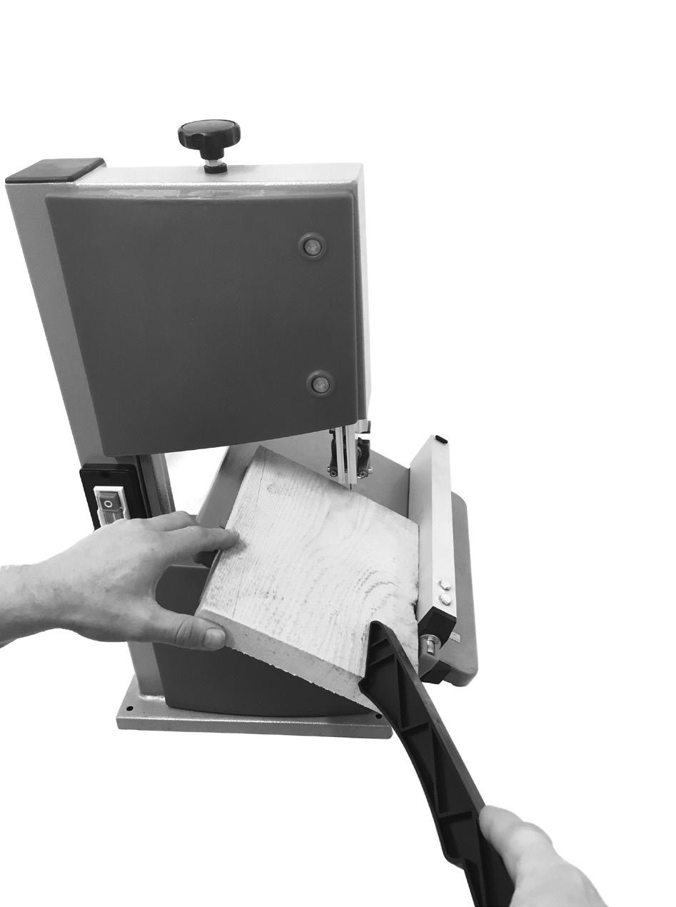
3 m GB Warning! Danger to life, risk of injury or damage to the tool are possible by ignoring! HU SI CZ SK Vigyázz! Életveszély, sérülések kockázatát vagy károsíthatják a szerszám esetén nem tartása! Pozor! Življenjska nevarnost, tveganje za poškodbe ali škodo na orodju v primeru neupoštevanja! Pozor! Možná za nedodržení Nebezpečí ohrožení života, riziko zranění nebo poškození nářadí! Pozor! Nebezpečenstvo ohrozenia života, riziko zranenia alebo poškodenia náradia v prípade nedodržania pokynov! DE AT CH Warnung! Bei Nichteinhaltung Lebensgefahr, Verletzungsgefahr oder Beschädigung des Werkzeugs möglich! GB Read and follow the operating and safety instructions before you start working with this power tool! HU Üzembe helyezés előtt olvassa el a kezelési útmutatót és a biztonsági előírásokat, és mindig tartsa be azokat! SI Pred zagonom preberite navodila za uporabo in varnostne napotke ter jih upoštevajte! CZ Před uvedením do provozu si přečtěte a dodržujte návod k obsluze a bezpečnostní pokyny. SK Pred uvedením do prevádzky si prečítajte návod na obsluhu a bezpečnostné upozornenia a dodržiavajte! DE AT CH Vor Inbetriebnahme Bedienungsanleitung und Sicherheitshinweise lesen und beachten! GB Wear safety goggles! HU Viseljen védőszemüveget! SI Nosite zaščitna očala! CZ Noste ochranné brýle! SK Noste ochranné okuliare! DE AT CH Schutzbrille tragen! GB Wear protective gloves. HU Viseljen védőkesztyűt. SI Nositi zaščitne rokavice. CZ Noste ochranné rukavice. SK Pri štartovaní ochranné rukavice. DE AT CH Tragen Sie Schutzhandschuhe. GB Wear ear-muffs! HU Viseljen hallásvédőt! SI Nosite zaščito sluha! CZ Noste ochranná sluchátka! SK Noste ochranu sluchu! DE AT CH Gehörschutz tragen! GB Attention! Observe the direction of rotation. HU Vigyázz! Fűrészszalag iránya. SI Pozor! Upoštevajte smer vrtenja. CZ Pozor! Sledujte směr otáčení. SK Pozor! Dodržujte smer otáčania. DE AT CH Achtung! Drehrichtung beachten. GB Wear a breathing mask! HU Porképződésnél viseljen légzőmaszkot! SI Pri prašenju nosite zaščito dihal! CZ Bude-li se při práci prášit, noste ochranu dýchacích cest! SK Pri tvorbe prachu noste ochranu dýchania! DE AT CH Bei Staubentwicklung Atemschutz tragen! GB Important! Risk of injury! Never reach into the running saw blade! HU Figyelem! Sérülésveszély! Ne nyúljon a mozgó fűrészszalagba! SI Pozor! Nevarnost poškodb! Ne posegajte v delujoč žagin trak! CZ Pozor! Nebezpečí poranění! Nesahejte do spuštěného pilového pásu! SK Pozor! Nebezpečenstvo poranenia! Nesiahajte do bežiaceho pílového pásu! DE AT CH Achtung! Verletzungsgefahr! Nicht in das laufende Sägeblatt greifen! GB HU SI CZ SK DE AT CH Attention! Before installation, cleaning, alterations, maintenance, storage and transport switch off the device and disconnect it from the power supply. Figyelmeztetés! A telepítés előtt, takarítás, átalakítás, karbantartás, tárolás és szállítás kapcsoljuk ki a készüléket, és húzza ki a tápegység. Opozorilo! Pred namestitvijo, čiščenje, rekonstrukcije, vzdrževanje, skladiščenje in prevoz izklopite napravo in jo izključite iz napajanja. Pozor! Před instalací, čištění, změny, údržby, skladování a přepravu zapnete přístroj a odpojte jej od elektrické sítě. Pozor! Pred inštaláciou, čistenie, zmeny, údržby, skladovanie a prepravu zapnete prístroj a odpojte ho od elektrickej siete. Achtung! Vor Montage, Reinigung, Umbau, Instandhaltung, Lagerung und Transport müssen Sie das Gerät ausschalten und von der Stromversorgung trennen.


4 1a b 1c d


5


6
7
8 Table of contents: Page: 1. Introduction 2 2. Device description 2 3. Scope of delivery 2 4. Intended use 3 5. Safety information 3 6. Technical data 5 7. Before starting the equipment 5 8. Attachment 6 9. Operation Working instructions Electrical connection Cleaning, maintenance and storage Disposal and recycling Transport Troubleshooting Warranty certificate Declaration of conformity 71 GB 1
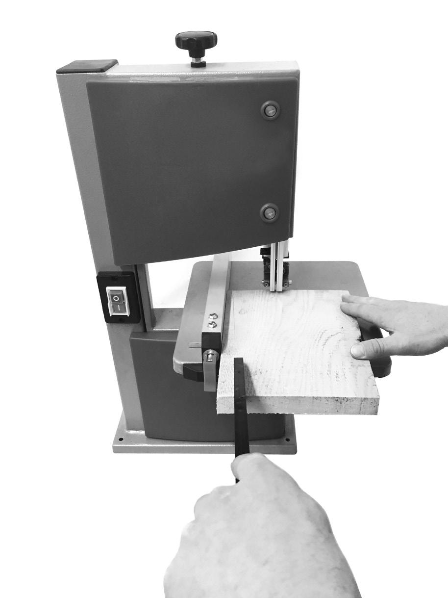
9 1. Introduction MANUFACTURER: scheppach Fabrikation von Holzbearbeitungsmaschinen GmbH Günzburger Straße 69 D Ichenhausen Dear Customer, we hope your new tool brings you much enjoyment and success. NOTE: According to the applicable product liability laws, the manufacturer of the device does not assume liability for damages to the product or damages caused by the product that occurs due to: Improper handling, Non-compliance of the operating instructions, Repairs by third parties, not by authorized service technicians, Installation and replacement of non-original spare parts, Application other than specified, A breakdown of the electrical system that occurs due to the non-compliance of the electric regulations and VDE regulations 0100, DIN / VDE0113. We recommend: Read through the complete text in the operating instructions before installing and commissioning the device. The operating instructions are intended to help the user to become familiar with the machine and take advantage of its application possibilities in accordance with the recommendations. The operating instructions contain important information on how to operate the machine safely, professionally and economically, how to avoid danger, costly repairs, reduce downtimes and how to increase reliability and service life of the machine. In addition to the safety regulations in the operating instructions, you have to meet the applicable regulations that apply for the operation of the machine in your country. Keep the operating instructions package with the machine at all times and store it in a plastic cover to protect it from dirt and moisture. Read the instruction manual each time before operating the machine and carefully follow its information. The machine can only be operated by persons who were instructed concerning the operation of the machine and who are informed about the associated dangers. The minimum age requirement must be complied with. In addition to the safety requirements in these operating instructions and your country s applicable regulations, you should observe the generally recognized technical rules concerning the operation of woodworking machines. We accept no liability for damage or accidents which arise due to non-observance of these instructions and the safety information. 2. Device description (Fig. 1-16) 1. Clamping screw 2. Top saw band roller 3. Rubber surface 4. Saw band guard 5. Top saw band guide 6. Table insert 7. Saw table 8. Bottom saw band roller 9. Foot 10. Cover locking mechanism 11. Side cover 12. On/off switch 13. Locking screw for top saw band roller 14. Set screw for top saw band roller 15. Machine frame 16. Mains cable 17. Degree scale for swivel range 18. Motor 19. Extraction nozzle 20. Locking handle for saw table 21. Bandsaw blade 22. Adjustment handle for saw band guide 23. Locking handle for saw band guide 24. Parallel stop 25. Clamping bar for parallel stop 26. Push stick mm Allen key mm Allen key 29. Screwdriver 30. Open-ended spanner 31. Wing nut 32. Clamping plate 33. Knurled nut 34. U-reinforcement 35. Allen screw for top support bearing 36. Top support bearing 37. Top guide pin 38. Allen screw for top guide pins 39. Retainer (top) 40. Allen screw top retainer (2x) 41. Allen screw bottom support bearing 42. Bottom support bearing 43. Screw bottom retainer 44. Saw band protection 45. Allen screw for bottom guide pins 46. Bottom guide pin 47. Retainer (bottom) 48. Push Stick retainer 49. Screw (saw table adjustment) 50. Nut (saw table adjustment) mm Allen key 3. Scope of delivery Open the packaging and remove the device carefully. Remove the packaging material as well as the packaging and transport bracing (if available). Check that the delivery is complete. Check the device and accessory parts for transport damage. 2 GB
10 If possible, store the packaging until the warranty period has expired. ATTENTION The device and packaging materials are not toys! Children must not be allowed to play with plastic bags, film and small parts! There is a risk of swallowing and suffocation! Bandsaw / Bandsaw blade (pre-assembled) Saw table Push stick Parallel stop Open-ended spanner, size 10/13 Allen key, size 3/4/5 Screwdriver Original operating instructions 4. Intended use The band saw is designed to perform longitudinal and cross cuts on timber or wood-type materials. To cut round materials you must use suitable holding devices. The equipment is to be used only for its prescribed purpose. Any other use is deemed to be a case of misuse. The user / operator and not the manufacturer will be liable for any damage or injuries of any kind caused as a result of this. The machine is to be operated only with suitable saw blades. To use the machine properly you must also o serve the safety regulations, the assembly instructions and the operating instructions to be found in this manual. All persons who use and service the machine have to be acquainted with this manual and must be informed about the machine s potential hazards. It is also imperative to observe the accident prevention regulations in force in your area. The same applies for the general rules of occupational health and safety. The manufacturer shall not be liable for any changes made to the machine nor for any damage resulting from such changes. Even when the machine is used as prescribed it is still impossible to eliminate certain residual risk factors. The following hazards may arise in connection with the machine s construction and design: Damage to hearing if ear-muffs are not used as necessary. Harmful emissions of wood dust when used in closed rooms. Contact with the blade in the uncovered cutting zone. Injuries (cuts) when changing the blade. Injury from catapulted workpieces or parts of workpieces. Crushed fingers. Kickback Tilting of the workpiece due to inadequate support. Touching the blade. Catapulting of pieces of timber and workpieces. Please note that our equipment has not been designed for use in commercial, trade or industrial applications. Our warranty will be voided if the equipment is used in commercial, trade or industrial businesses or for equivalent purposes. 5. Safety information Attention! The following basic safety measures must be observed when using electric tools for protection against electric shock, and the risk of injury and fire. Read all these notices before using the electric tool and keep the safety instructions for later reference. Safe work 1. Keep the work area orderly Disorder in the work area can lead to accidents. 2. Take environmental influences into account Do not expose electric tools to rain. Do not use electric tools in a damp or wet environment. Make sure that the work area is well-illuminated. Do not use electric tools where there is a risk of fire or explosion. 3. Protect yourself from electric shock Avoid physical contact with earthed parts (e.g. pipes, radiators, electric ranges, cooling units). 4. Keep other people away Do not let other people especially children touch the electric tool or its cable. Keep them clear of the work area. 5. Securely store unused electric tools Unused electric tools should be stored in a dry, elevated or closed location out of the reach of children. 6. Do not overload your electric tool They work better and more safely in the specified output range. 7. Use the correct electric tool Do not use low-output electric tools for heavy work. Do not use the electric tool for purposes for which it is not intended. For example, do not use handheld circular saws for the cutting of branches or logs. Do not use the electric tool to cut firewood. 8. Wear suitable clothing Do not wear wide clothing or jewellery, which can become entangled in moving parts. When working outdoors, anti-slip footwear is recommended. Tie long hair back in a hair net. 9. Use protective equipment Wear protective goggles. Wear a mask when carrying out dust-creating work. 10. Connect the dust extraction device if you will be processing wood, materials similar to wood, or plastics. If connections for dust extraction and a collecting device are present, make sure that they are connected and used properly. When processing wood, materials similar to wood, and plastics. Operation in enclosed spaces is only permitted with the use of a suitable extraction system. 11. Do not use the cable for purposes for which it is not intended Do not use the cable to pull the plug out of the outlet. Protect the cable from heat, oil and sharp edges. 12. Secure the workpiece Use the clamping devices or a vice to hold the workpiece in place. In this manner, it is held more securely than with your hand. GB 3
11 An additional support is necessary for long workpieces (table, trestle, etc.) in order to prevent the machine from tipping over. Always press the workpiece firmly against the working plate and stop in order to prevent bouncing and twisting of the workpiece. 13. Avoid abnormal posture Make sure that you have secure footing and always maintain your balance. Avoid awkward hand positions in which a sudden slip could cause one or both hands to come into contact with the saw blade. 14. Take care of your tools Keep cutting tools sharp and clean in order to be able to work better and more safely. Follow the instructions for lubrication and for tool replacement. Check the connection cable of the electric tool regularly and have it replaced by a recognised specialist when damaged. Check extension cables regularly and replace them when damaged. Keep the handle dry, clean and free of oil and grease. 15. Pull the plug out of the outlet Never remove loose splinters, chips or jammed wood pieces from the running saw blade. During non-use of the electric tool or prior to maintenance and when replacing tools such as saw blades, bits, milling heads. When the saw blade is blocked due to abnormal feed force during cutting, turn the machine off and disconnect it from power supply. Remove the work piece and ensure that the saw blade runs free. Turn the machine on and start new cutting operation with reduced feed force. 16. Do not leave a tool key inserted Before switching on, make sure that keys and adjusting tools are removed. 17. Avoid inadvertent starting Make sure that the switch is switched off when plugging the plug into an outlet. 18. Use extension cables for outdoors Only use approved and appropriately identified extension cables for use outdoors. Only use cable reels in the unrolled state. 19. Remain attentive Pay attention to what you are doing. Remain sensible when working. Do not use the electric tool when you are distracted. 20. Check the electric tool for potential damage Protective devices and other parts must be carefully inspected to ensure that they are fault-free and function as intended prior to continued use of the electric tool. Check whether the moving parts function faultlessly and do not jam or whether parts are damaged. All parts must be correctly mounted and all conditions must be fulfilled to ensure fault-free operation of the electric tool. The moving protective hood may not be fixed in the open position. Damaged protective devices and parts must be properly repaired or replaced by a recognised workshop, insofar as nothing different is specified in the operating manual. Damaged switches must be replaced at a customer service workshop. Do not use any faulty or damaged connection cables. Do not use any electric tool on which the switch cannot be switched on and off. 21. ATTENTION! The use of other insertion tools and other accessories can entail a risk of injury. 22. Have your electric tool repaired by a qualified electrician This electric tool conforms to the applicable safety regulations. Repairs may only be performed by an electrician using original spare parts. Otherwise accidents can occur. Additional safety instructions Wear safety gloves whenever you carry out any maintenance work on the blade! When cutting round or irregularly shaped wood, use a device to stop the workpiece from twisting. When cutting boards in upright position, use a device to prevent kick-back. A dust extraction system designed for an air velocity of 20 m/s should be connected in order to comply with woodworking dust emission values and to ensure reliable operation. Give these safety regulations to all persons who work on the machine. Do not use this saw to cut fire wood. The machine is equipped with a safety switch to prevent it being switched on again accidentally after a power failure. Before you use the machine for the first time, check that the voltage marked on the rating plate is the same as your mains voltage. If you use a cable reel, the complete cable has to be pulled off the reel. Persons working on the machine should not be distracted. Note the direction of rotation of the motor and blade. Never dismantle the machineʼs safety devices or put them out of operation. Never cut workpieces which are too small to hold securely in your hand. Never remove loose splinters, chips or jammed pieces of wood when the saw blade is running. It is imperative to observe the accident prevention regulations in force in your area as well as all other generally recognized rules of safety. Note the information published by your professional associations. Adjustable protective devices have to be adjusted as close as possible to the workpiece. Important! Support long workpieces (e.g. with a roller table) to prevent them sagging at the end of a cut. Make sure the blade guard (4) is in its lower position when the saw is being transported. Safety guards are not to be used to move or misuse the machine. 4 GB
12 Blades that are misshapen or damaged in any way must not be used. If the table insert is worn, replace it. Never operate the machine if either the door protecting the blade or the detachable safety device are open. Ensure that the choice of blade and the selected speed are suitable for the material to be cut. Do not begin cleaning the blade until it has come to a complete standstill. For straight cuts of small workpieces against the longitudinal limit stop the push stick has to be used. Wear gloves when handling the saw blade and rough materials The bandsaw blade guard should be in its lowest position close to the bench during transport. For miter cuts when the table is tilted, the parallel stop must be positioned on the lower part of the table. Never use guards to lift or transport items. Ensure that the bandsaw blade guards are used and correctly adjusted. Keep your hands a safety distance away from the bandsaw blade. Use a push stick for narrow cuts. The push stick has to be stored on the intended device, so that it can be reached from normal working position and is always ready to be used. In the normal operating position the operator is in front of the machine. Warning! This electric tool generates an electromagnetic field during operation. This field can impair active or passive medical implants under certain conditions. In order to prevent the risk of serious or deadly injuries, we recommend that persons with medical implants consult with their physician and the manufacturer of the medical implant prior to operating the electric tool. Remaining hazards The machine has been built using modern technology in accordance with recognized safety rules. Some remaining hazards, however, may still exist. Risk of injury for fingers and hands by the rotating saw band due to improper handling of the work piece. Risk of injury through the hurling work piece due to improper handling, such as working without the push stick. Risk of damaging your health due to wood dust and wood chips. Wear personal protective cloth such as goggles. Use a fitting dust extractor. Risk of injury due to defective saw band. Regularely check saw band for such defects. Risk of injury for fingers and hands while changing saw band. Wear proper gloves. Risk of injury due to starting saw band while switching on the machine. The use of incorrect or damaged mains cables can lead to injuries caused by electricity. Wear only closefitting clothes. Remove rings, bracelets and other jewelry. For the safety of long hair, wear a cap or hair net. Even when all safety measures are taken, some remaining hazards which are not yet evident may still be present. Remaining hazards can be minimized by following the instructions in General safety instructions Proper Use and in the entire operating manual. 6. Technical data Electro motor V 50 Hz Power S1 350W* Revolutions n min -1 Saw band length Saw band width Saw band width max. Cutting speed Passage height Passage width Table size 1400 mm 3,5-12 mm 12 mm 900 m/min 0-80 mm 200 mm 300 x 300 mm Slewing range of the table 0 bis 45 Max. size of the workpiece Overall weight Subject to technical modifications! * Operating mode S1, continous operation. 400 x 400 x 80 mm 14,8 kg The work piece must have a minimum height of 3 mm and a minimum width of 10 mm. The total noise values determined in accordance with EN Sound pressure level L pa Uncertainty K pa Sound power level L WA Uncertainty K WA 77,4 db(a) 3 db 90,4 db(a) 3 db Wear hearing protection! The effects of noise can cause a loss of hearing. Keep the noise level and vibration to a minimum! Only use faultless devices. Maintain and clean the device at regular intervals. Adapt your working methods to the device. Do not overload the device. Have the device checked if necessary. Switch the device off if it is not in use. 7. Before starting the equipment Make sure the machine stands securely, i.e. bolt it to a workbench or solid base. There are two holes for this purpose in the machine foot. The saw table must be mounted correctly. All covers and safety devices have to be properly fitted before the machine is switched on. It must be possible for the blade to run freely. When working with wood that has been processed before, watch out for foreign bodies such as nails or screws etc. GB 5
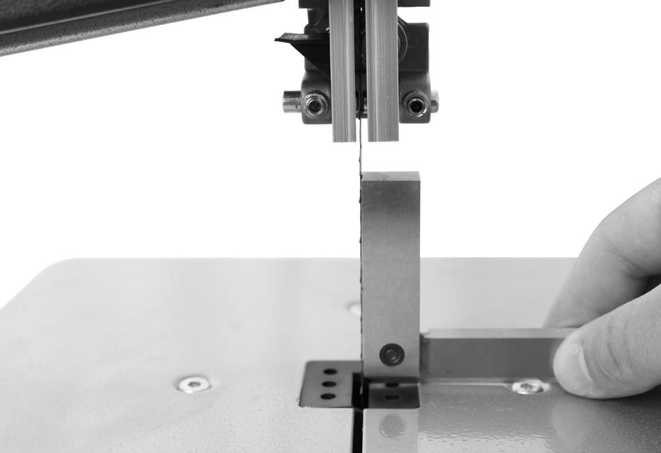
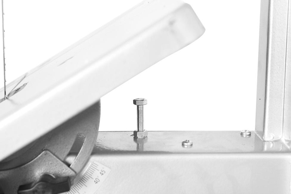
13 Before you actuate the On/Off switch, make sure that the saw blade is correctly fitted and that the machine s moving parts run smoothly. Before you connect the machine to the power supply, make sure the data on the rating plate is the same as that for your mains. 8. Attachment ATTENTION! Before all maintenance, set-up and assembly work on the band saw, unplug the mains plug. Assembly tools 1 Open-ended spanner, size 10/13 1 Allen key, size 3 1 Allen key, size 4 1 Screwdriver The saw table is not assembled for packaging reasons. 8.1 Assembling the saw table (Fig. 2-4) Remove the wing nut (31), the locking handle (20), the two washers and the clamping plate (32). (Fig. 2) Remove the two knurled nuts (33), the U-reinforcement (34) and the two countersunk screws M6x16 from the saw table. (Fig. 3) Guide the saw table (7) over the Bandsaw blade (21). Fasten it to the two screws on the machine frame with the plate (32), the two washers, the wing nut (31) and the locking handle (20). (Fig. 4) Fasten the U-reinforcement (34) to the front side of the saw table with 2 countersunk screws M6x16 and 2 knurled nuts (33). (Fig.3) 8.2 Tensioning the saw band (Fig. 1a) ATTENTION! If the saw is at a standstill for an extended period the saw band tension must be relieved, i.e. before switching the saw on it is necessary to check the saw blade tension. Turn the clamping screw (1) clockwise to tension the Bandsaw blade (21). The correct tension of the saw band can be determined by pressing the finger laterally against the saw band, roughly centrally between the two saw band rollers (2+8). The Bandsaw blade (21) should only depress slightly (approx. 1-2 mm) here. The sufficiently tensioned saw band makes a metallic sound when tapped. Relieve the saw band tension if it is not in use for an extended time, so that it does not become overstretched. ATTENTION! With high tension, the saw band may break. RISK OF INJURY! If the tension is too low, the driven saw band roller (8) may spin, resulting in the saw band coming to a standstill. 8.3 Adjusting the saw band (Fig. 1a+1b) ATTENTION! Before it is possible to implement the saw band setting, the saw band must be tensioned correctly. Open the side covers (11) by undoing the cover locking mechanisms (10) with the help of the screwdriver (29). Slowly turn the saw band roller (2) clockwise. The Bandsaw blade (21) should run centrally on the saw band roller (2). If this is not the case, the angle of the top saw band roller (2) must be corrected. If the Bandsaw blade (21) runs more towards the rear edge of the saw band roller (2) then the set screw (14) must be rotated anticlockwise. Open the locking screw for the top saw band roller (13). Turn the bottom saw band roller (8) slowly by hand, to check the position of the Bandsaw blade (21). If the Bandsaw blade (21) runs more towards the front edge of the saw band roller (2) then the set screw (14) must be rotated clockwise. After setting the top saw band roller (2), check the position of the Bandsaw blade (21) on the bottom saw band roller (8). The Bandsaw blade (21) should also lie centrally on the saw band roller (8) here. If this is not the case, the angle of the top saw band roller (2) must be adjusted again. Turn the saw band roller a few times, until the adjustment of the top saw band roller (2) acts on the saw band position on the bottom saw band roller (8). Tighten the locking screw for the top saw band roller (13). Once adjustment is complete, close the side covers (11) again and secure with the cover locking mechanisms (10) with the help of the screwdriver (29). 8.4 Adjusting the saw band guide (Fig. 5-8) Both the support bearing ( ) and the guide pins ( ) must be readjusted after every saw band change. Open the side covers (11) by undoing the cover locking mechanisms (10) with the help of the screwdriver (29) Top support bearing (36) ( Fig. 5) Undo Allen screw for top support bearing (35). Move support bearing (36) sufficiently far that it just no longer touches the Bandsaw blade (21) (distance max. 0.5 mm). Retighten the Allen screw for the top support bearing (35) Adjusting the bottom support bearing (42) (Fig. 7) Disassemble the saw table as per 9.1 in the opposite direction. Undo Allen screw for bottom support bearing (41). Move bottom support bearing (42) sufficiently far that it just no longer touches the Bandsaw blade (21) (distance max. 0.5 mm). Retighten Allen screw for bottom support bearing (41) Adjusting the top guide pins (37) Undo Allen screws for top retainer (40) Move top retainer (39), top guide pins (37), until the front edge of the guide pins (37) is approx. 1 mm behind the tooth base of the saw band. Retighten Allen screws for top retainer (40). ATTENTION! The saw band will be unusable if the teeth touch the guide pins with the saw band running. Undo Allen screws for top guide pins (38). Slide the guide pins (37) in the direction of the saw band! Attention! The distance between the guide pins (37) and Bandsaw blade (21) must not exceed 0.5 mm. (Saw band must not jam) Retighten Allen screws (38). 6 GB
14 Turn the top saw band roller (2) a few times in a clockwise direction. Check the setting of the top guide pins (38) again and adjust if necessary. If necessary, adjust the top support bearing (36) (8.4.1) Adjusting the bottom guide pins (46) (Fig.7+8) Disassemble saw table (7) Undo screw for bottom retainer (43) (Allen key, size 5) Move bottom retainer (47), bottom guide pins (46), until the front edge of the bottom guide pins (46) is approx. 1 mm behind the tooth base of the saw band. Retighten screw for bottom retainer (43). ATTENTION! The saw band will be unusable if the teeth touch the guide pins with the saw band running. Undo Allen screws for bottom guide pins (45). Slide the two bottom guide pins (46) sufficiently far in the direction of the saw band that the distance between the guide pins (46) and Bandsaw blade (21) is max. 0.5 mm. (Saw band must not jam) Retighten Allen screws for bottom guide pins (45). Turn the bottom saw band roller (8) a few times in a clockwise direction. Check the setting of the bottom guide pins (46) again and adjust if necessary. If necessary, adjust the bottom support bearing (42) (8.4.2). 8.5 Adjusting the top saw band guide (5) (Fig. 9) Undo locking handle for saw band guide (23). Turn the adjustment handle for the saw band guide (22) to lower the saw band guide (5) as closely as possible (distance approx. 2-3 mm) over the material to be cut. Retighten locking handle (23). Check the setting before every cutting process and adjust if necessary. 8.6 Adjusting the saw table (7) to 90 (Fig ) Set the top saw blade guide (5) fully upwards. Undo locking handle (20) and wing nut (31) (Fig. 2). Place the angle bracket between the Bandsaw blade (21) and saw table (7). Angle bracket not included in the scope of supply. Tilt the saw table (7) by turning, until the angle to the Bandsaw blade (21) is precisely 90. If the saw table is already on the screw (49) and a 90 angle cannot be set, undo the nut (50) and shorten the screw (49) by turning in a clockwise direction. Retighten the locking handle (20) and wing nut (31). Also undo the nut (50). Adjust the screw (49) sufficiently that the saw table touches the underside. Retighten the nut (50) to fix the screw (49) in position. 8.7 Which saw band to use The saw band supplied in the band saw is intended for universal use. The following criteria should be considered when selecting the saw band: It is possible to cut tighter radii with a narrow saw band than with a wide saw band. A wide saw band is used if a straight cut is required. This is important in particular when cutting wood. The saw band has a tendency to follow the wood grain and therefore deviates easily from the desired cutting line. Fine-toothed saw bands cut more smoothly, but also more slowly than coarse saw bands. Attention: Never use bent or torn saw bands! 8.8 Replacing the saw band (Fig. 1a+1b+14) Set the saw band guide (5) at approx. half height between the saw table (7) and machine frame (15). Undo the cover locking mechanisms (10) and open the side covers (11). Remove U-reinforcement (34) as described in 8.1. Relieve the Bandsaw blade (21) tension by turning the clamping screw (1) anti-clockwise. Remove the Bandsaw blade (21) from the saw band rollers (2+8) and through the slot in the saw table (7). Place the new Bandsaw blade (21) centrally on both saw band rollers (2+8). The teeth of the Bandsaw blade (21) must point downwards in the direction of the saw table (Fig. 6). Tension the Bandsaw blade (21) (see 8.2) Close the side cover (11) again. Re-install the U-reinforcement (34). 8.9 Replacing the table insert (Fig. 13) In case of wear or damage, the table insert (6) must be replaced; otherwise there is an increased risk of injury. Remove the worn table insert (6) by lifting it up and out. Installation of the new table insert takes place in reverse order Extraction nozzle (Fig. 1b) The band saw is equipped with an extraction nozzle (19) Ø 40 mm for chips. Only operate the device with a suitable extraction system. Check and clean the suction channels at regular intervals Push Stick retainer (Fig. 12) The Push Stick retainer (48) is pre-mounted on the machine frame. If unused, the Push stick (26) must always be stowed in the Push Stick retainer. 9. Operation 9.1 On/Off switch (12) (Fig. 15) To turn the machine on, press the green button I. To turn the machine off again, press the red button 0. The band saw is equipped with an undervoltage switch. With a power failure, the band saw must be switched back on again. 9.2 Parallel stop (Fig. 16) Press the clamping bar (25) of the parallel stop (24) upwards Slide the parallel stop (24) left or right of the Bandsaw blade (21) on the saw table (7) and set to the desired measurement. GB 7
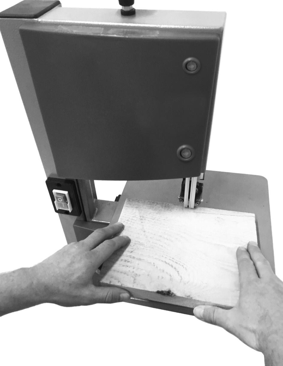
15 Press the clamping bar (25) down to fix the parallel stop (24) in place. In order to increase the clamping force of the clamping bar (25), rotate it clockwise until the parallel stop is sufficiently fixed in place. Make sure that the parallel stop (24) always runs parallel to the Bandsaw blade (21). 9.3 Angled cuts (Fig. 17) In order to execute angled cuts parallel to the Bandsaw blade (21), it is possible to tilt the saw bench (7) forwards from Undo locking handle (20) and wing nut (31). Tilt saw bench (7) forwards, until the desired angle is set on the degree scale (17). Retighten the locking handle (20) and wing nut (31). Attention: With a tilted saw table (7), the parallel stop (24) must always be fitted to the right of the Bandsaw blade (21) in the working direction. This prevents the workpiece from slipping. 10. Working instructions The following recommendations are examples of the safe use of band saws. The following safe working methods should be seen as an aid to safety. They cannot be applied suitably completely or comprehensively to every use. They cannot treat every possible dangerous condition and must be interpreted carefully. Connect the machine to a suction unit when working in closed rooms. A suction device which conforms with commercial regulations must be used for suction in commercial areas. Loosen the sawband when the machine is not in operation (e.g. after finishing work). Attach a notice on the tension of the saw band to the machine for the next user. Collect unused sawbands and store them safely in a dry place. Check for faults (teeth, cracks) before use. Do not use faulty sawbands! Wear suitable gloves when handling sawbands. All protective and safety devices must be securely mounted on the machine before beginning work. Never clean the sawband or the sawband guide with a hand-held brush or scraper while the sawband is running. Resin-covered sawbands impair working safety and must be cleaned regularly. For your own protection, wear protective glasses and hearing protection. Wear a hairnet if you have long hair. Roll up loose sleeves over the elbows. Always position the sawband guide as near the workpiece as possible when working. Insure sufficient lighting in the work area and around the machine. Always use the fence for straight cuts to keep the workpiece from tipping or slipping away. When working on narrow workpieces with manual feed, use the push stick. For diagonal cuts, place the saw bench in the appropriate position and guide the workpiece on the fence. In order to cut dovetail tenons and teeth or wedges, bring the saw table into the corresponding position on the angle scale. For arced and irregular cuts, push the workpiece evenly using both hands with the fingers together. Hold the workpiece with your hands on a safe area. Use a pattern for repeated arced or irregular cuts. Insure that the workpiece does not roll when cutting round pieces. Attention! After every new setting, we recommend performing a test cut, in order to check the dimensional settings. With all cutting processes, the top saw band guide (5) must be positioned as close as possible to the workpiece (see 8.5). The workpiece must always be guided with both hands and kept flat against the saw table (7). This prevents the Bandsaw blade (21) from jamming. Forward feeding should always take place with an even pressure, which is just sufficient for the saw band to cut through the material with ease without becoming blocked. Always use the parallel stop (24) for all cutting processes that it can be used for. It is better to perform a cut in a single working step than in multiple steps, which may require that the workpiece be drawn back. However, if it is not possible to avoid drawing the workpiece back then the band saw must be switched off first. Only draw the workpiece back once the Bandsaw blade (21) has come to a standstill. When sawing, the workpiece must always be guided by its longest side. Attention! When processing narrower workpieces it is essential to use a Push stick. The Push stick (26) must always be stored within reach, on the Push Stick retainer (48) provided for this purpose on the side of the saw Performing longitudinal cuts (Fig. 18) Here, a workpiece is cut in its longitudinal direction. Position the longitudinal fence (24) on the left side (if possible) of the Bandsaw blade (21), in accordance with the desired width. Lower the saw band guide (5) onto the workpiece (9.5). Switch on the saw (see 10.1). Press one edge of the workpiece against the longitudinal fence (24) with the right hand, whilst the flat side lies on the saw bench (7). Slide the workpiece at an even feed rate along the longitudinal fence (24) into the Bandsaw blade (21). Important: Long workpieces must be secured against tipping at the end of the cutting process (e.g. with reel-off stand, etc.) 10.2 Performing angled cuts (Fig. 17) Set saw bench to desired angle (see 9.3). Perform the cut as described under When producing angled cuts, only use the parallel stop to the right of the saw band Freehand cuts (Fig. 19) One of the most important features of a band saw is the ease with which it can cut curves and radii. Lower the saw band guide (5) onto the workpiece (see 8.5). Switch on the saw. 8 GB
16 Press the workpiece firmly onto the saw bench (7) and slowly slide into the Bandsaw blade (21). In many cases it is helpful to roughly saw curves and corners approximately 6 mm from the line. If it is necessary to saw curves that are too tight for the saw band used, auxiliary cuts must be sawn up to the front face of the curve, so that these fall off as wood waste when the final radius is sawn. 11. Electrical connection The electrical motor installed is connected and ready for operation. The connection complies with the applicable VDE and DIN provisions. The customer s mains connection as well as the extension cable used must also comply with these regulations. Important information In the event of an overloading the motor will switch itself off. After a cool-down period (time varies) the motor can be switched back on again. Damaged electrical connection cable The insulation on electrical connection cables is often damaged. This may have the following causes: Passage points, where connection cables are passed through windows or doors. Kinks where the connection cable has been improperly fastened or routed. Places where the connection cables have been cut due to being driven over. Insulation damage due to being ripped out of the wall outlet. Cracks due to the insulation ageing. Such damaged electrical connection cables must not be used and are life-threatening due to the insulation damage. Check the electrical connection cables for damage regularly. Make sure that the connection cable does not hang on the power network during the inspection. Electrical connection cables must comply with the applicable VDE and DIN provisions. Only use connection cables with the marking H05VV-F. The printing of the type designation on the connection cable is mandatory. AC motor The mains voltage must be V~ 50 Hz. Extension cables up to 25 m long must have a cross-section of 1.5 mm 2. Connections and repairs of electrical equipment may only be carried out by an electrician. Please provide the following information in the event of any enquiries: Type of current for the motor Machine data - type plate Machine data - type plate 12. Cleaning, maintenance, and storage m Important! Prior to any adjustment, maintenance or service work disconnect the mains power plug! Cleaning Keep all safety devices, air vents and the motor housing free of dirt and dust as far as possible. Wipe the equipment with a clean cloth or blow it with compressed air at low pressure. We recommend that you clean the device immediately each time you have finished using it. Maintenance There are no parts inside the equipment which require additional maintenance. Storage Store the device and its accessories in a dark, dry and frostproof place that is inaccessible to children. The optimum storage temperature is between 5 and 30 C. Store the power tool in original packaging. Cover the electrical tool in order to protect it from dust and moisture. Store the operating manual with the electrical tool. 13. Disposal and recycling The equipment is supplied in packaging to prevent it from being damaged in transit. The raw materials in this packaging can be reused or recycled. The equipment and its accessories are made of various types of material, such as metal and plastic. Defective components must be disposed of as special waste. Ask your dealer or your local council. The packaging is wholly composed of environment allyfriendly materials that can be disposed of at a local recycling centre. Contact your local refuse disposal authority for more details of how to dispose of your worn out electrical devices. Old devices must not be disposed of with household waste! This symbol indicates that this product must not be disposed of together with domestic waste in compliance with the Directive (2012/19/EU) pertaining to waste electrical and electronic equipment (WEEE). This product must be disposed of at a designated collection point. This can occur, for example, by handing it in at an authorised collecting point for the recycling of waste electrical and electronic equipment. Improper handling of waste equipment may have negative consequences for the environment and human health due to potentially hazardous substances that are often contained in electrical and electronic equipment. GB 9
17 By properly disposing of this product, you are also contributing to the effective use of natural resources. You can obtain information on collection points for waste equipment from your municipal administration, public waste disposal authority, an authorised body for the disposal of waste electrical and electronic equipment or your waste disposal company. 14. Transport The machine must only be lifted and transported on its frame or the frame plate. Never lift the machine at the safety devices, the adjusting levers, or the sawing table. During the transport the saw blade protection must be in the lowest position and near the table. Never raise at the table! Unplug the machine from the mains during transport. 15. Troubleshooting Fault Possible cause Remedy Motor does not work The motor starts up slowly and does not reach operating speed. Motor makes excessive noise The motor does not reach its full power. Motor overheats easily. Saw cut is rough or wavy Workpiece pulls away and/or splinters Saw blade is not running straight Burn marks appear on the wood during the cutting work Saw blade jams during cutting work Motor, cable or plug defective, fuses burnt Housing cover open (limit switch) Voltage too low, coils damaged, capacitor burnt Coils damaged, motor defective Circuits in the network are overloaded (lamps other motors, etc.) Overloading of the motor, insufficient cooling of the motor Saw blade dull, tooth shape not appropriate for the material thickness Excessive cutting pressure and/or saw blade not suitable for use a) Guide has been wrongly set b) Wrong saw blade a) Blunt saw blade b) Wrong saw blade a) Blunt saw blade b) Deposits on the saw blade c) Guide has been set poorly Arrange for inspection of the machine by a specialist. Never repair the motor yourself. Danger! Check fuses and replace as necessary Close housing cover exactly Contact the utility provider to check the voltage. Arrange for inspection of the motor by a specialist. Arrange for replacement of the capacitor by a specialist Arrange for inspection of the motor by a specialist Do not use any other equipment or motors on the same circuit Avoid overloading the motor while cutting, remove dust from the motor in order to ensure optimal cooling of the motor Resharpen saw blade and/or use suitable saw blade Insert suitable saw blade a) Set the saw blade guide according to the operating instructions b) Select a saw blade according to the operating instructions a) Change the saw blade b) Select a saw blade according to the operating instructions a) Change the saw blade b) Clean the saw blade c) Set the saw blade guide according to the operating instructions Service information Please note that the following parts of this product are subject to normal or natural wear and that the following parts are therefore also required for use as consumables. Wear parts*: Bandsaw blade, table inserts, Push stick * Not necessarily included in the scope of delivery! 10 GB
18 16. Warranty certificate Dear Customer, All of our products undergo strict quality checks to ensure that they reach you in perfect condition. In the unlikely event that your device develops a fault, please contact our service department at the address shown on this guarantee card. Of course, if you would prefer to call us then we are also happy to offer our assistance under the service number printed below. Please note the following terms under which guarantee claims can be made: These guarantee terms cover additional guarantee rights and do not affect your statutory warranty rights. We do not charge you for this guarantee. Our guarantee only covers problems caused by material or manufacturing defects, and it is restricted to the rectification of these defects or replacement of the device. Please note that our devices have not been designed for use in commercial, trade or industrial applications. Consequently, the guarantee is invalidated if the equipment is used in commercial, trade or industrial applications or for other equivalent activities. The following are also excluded from our guarantee: compensation for transport damage, damage caused by failure to comply with the installation/assembly instructions or damage caused by unprofessional installation, failure to comply with the operating instructions (e.g. connection to the wrong mains voltage or current type), misuse or inappropriate use (such as overloading of the device or use of non-approved tools or accessories), failure to comply with the maintenance and safety regulations, ingress of foreign bodies into the device (e.g. sand, stones or dust), effects of force or external influences (e.g. damage caused by the device being dropped) and normal wear resulting from proper operation of the device. The guarantee is rendered null and void if any attempt is made to tamper with the device. The guarantee is valid for a period of 3 years starting from the purchase date of the device. Guarantee claims should be submitted before the end of the guarantee period within two weeks of the defect being noticed. No guarantee claims will be accepted after the end of the guarantee period. The original guarantee period remains applicable to the device even if repairs are carried out or parts are replaced. In such cases, the work performed or parts fitted will not result in an extension of the guarantee period, and no new guarantee will become active for the work performed or parts fitted. This also applies when an on-site service is used. In order to assert your guarantee claim, please send your defective device postage-free to the address shown below. Please enclose either the original or a copy of your sales receipt or another dated proof of purchase. Please keep your sales receipt in a safe place, as it is your proof of purchase. It would help us if you could describe the nature of the problem in as much detail as possible. If the defect is covered by our guarantee then your device will either be repaired immediately and returned to you, or we will send you a new device. Of course, we are also happy offer a chargeable repair service for any defects which are not covered by the scope of this guarantee or for units which are no longer covered. To take advantage of this service, please send the device to our service address. Service-Hotline (GB): (0,00 EUR/Min.) Service- (GB): service.gb@scheppach.com Service Address (GB): GreatStar Europe Unit 55 Romsey Industrial Estate, Romsey Hampshire SO51 0HR GB 11
19 Tartalomjegyzék: Oldal: 1. Bevezetés A készülék leírása Szállított elemek Rendeltetésszerűi használat Biztonsági utasítások Technikai adatok Beüzemeltetés előtt Felépítés Kezelés Használati utasítás Elektromos csatlakoztatás Tisztítás, karbantartás és tárolás Megsemmisítés és újrahasznosítás Szállítás Hiaelhárítás Jótállási Tájékoztató Megfelelőségi nyilatkozat HU
ROLZ-2. Portable AV/Conference Center. Assembly Instructions
 1 ROLZ-2 Portable AV/Conference Center Assembly Instructions Rolz-2 Portable AV/Conference Center Part Drawing Description Qty Part Drawing Description Qty Hardware List A 1 ½ Flat Head Screw 2 EA P-1
UŽIVATELSKÁ PŘÍRUČKA
 UŽIVATELSKÁ PŘÍRUČKA Plni víry a naděje míříme kupředu. S odhodláním zlepšujeme své dovednosti. Zapomeňte na zklamání, ale nikoli na svůj nevyužitý potenciál. Touha překonat sám sebe a dosáhnout hranice
Litosil - application
 Litosil - application The series of Litosil is primarily determined for cut polished floors. The cut polished floors are supplied by some specialized firms which are fitted with the appropriate technical
ROLZ-2. Portable AV/Conference Center. Assembly Instructions
 1 ROLZ-2 Portable AV/Conference Center Assembly Instructions Rolz-2 Portable AV/Conference Center Part Drawing Description Qty Part Drawing Description Qty Hardware List A 1 ½ Flat Head Screw 2 EA P-1
GUIDELINES FOR CONNECTION TO FTP SERVER TO TRANSFER PRINTING DATA
 GUIDELINES FOR CONNECTION TO FTP SERVER TO TRANSFER PRINTING DATA What is an FTP client and how to use it? FTP (File transport protocol) - A protocol used to transfer your printing data files to the MAFRAPRINT
USER'S MANUAL FAN MOTOR DRIVER FMD-02
 USER'S MANUAL FAN MOTOR DRIVER FMD-02 IMPORTANT NOTE: Read this manual carefully before installing or operating your new air conditioning unit. Make sure to save this manual for future reference. FMD Module
MA251 (cz_en) Operating instructions. MA251 (cz_en) Montážní návod. Krimpovací kleště PV-CZM... pro MC3, MC4 a MC4-EVO 2
 Operating instructions. MA251 (cz_en) Montážní návod. Krimpovací kleště PV-CZM... pro MC3, MC4 a MC4-EVO 2") MA251 (cz_en) Montážní návod Krimpovací kleště PV-CZM... pro MC3, MC4 a MC4-EVO 2 MA251 (cz_en) Operating instructions Crimping pliers PV-CZM... for MC3, MC4 and MC4-EVO 2 Obsah Bezpečnostní pokyny...2
MA251 (cz_en) Montážní návod Krimpovací kleště PV-CZM... pro MC3, MC4 a MC4-EVO 2 MA251 (cz_en) Operating instructions Crimping pliers PV-CZM... for MC3, MC4 and MC4-EVO 2 Obsah Bezpečnostní pokyny...2
2N Voice Alarm Station
 2N Voice Alarm Station 2N Lift1 Installation Manual Version 1.0.0 www.2n.cz EN Voice Alarm Station Description The 2N Voice Alarm Station extends the 2N Lift1/ 2N SingleTalk with an audio unit installed
 11.12. 100 ΕΙΣΟΔΟΣ = E / ENTRANCE = E = = 1174 550 ΤΥΠΟΠΟΙΗΜΕΝΟ ΚΥ = 2000 (ΕΠΙΛΟΓΗ: 2100) / CH STANDARD = 2000 (OPTIONAL: 2100) 243 50 ΚΥ/CH + 293 ΚΥ/CH +103 100 ΚΥ /CH 6 11 6 20 100 0,25 ΚΑ (CO) + 45
PC/104, PC/104-Plus. 196 ept GmbH I Tel. +49 (0) / I Fax +49 (0) / I I
 / I Fax +49 (0) / I I") E L E C T R O N I C C O N N E C T O R S 196 ept GmbH I Tel. +49 (0) 88 61 / 25 01 0 I Fax +49 (0) 88 61 / 55 07 I E-Mail sales@ept.de I www.ept.de Contents Introduction 198 Overview 199 The Standard 200
E L E C T R O N I C C O N N E C T O R S 196 ept GmbH I Tel. +49 (0) 88 61 / 25 01 0 I Fax +49 (0) 88 61 / 55 07 I E-Mail sales@ept.de I www.ept.de Contents Introduction 198 Overview 199 The Standard 200
Size / Světlost : DN 1/4 to 4 / DN 1/4 až 4
 Size / Světlost : 1/4 to 4 / 1/4 až 4 Ends / Konce : Threaded BSP / Závitové BSP Min. Temperature / Minimální teplota : -20 C Max. Temperature / Maximální teplota : +180 C Max. Pressure / Maximální tlak
NÁVOD K NASTAVENÍ VODÍTEK PILOVÉHO PÁSU ADJUSTING SAW BLADE GUIDE
 CZ Návod k nastavení Pilového pásu EN User Manual Metal band saw NÁVOD K NASTAVENÍ VODÍTEK PILOVÉHO PÁSU ADJUSTING SAW BLADE GUIDE BS 115N / BS 128PRO / BS 712N / BS 712PRO Pásové pily na kov metal band
DATA SHEET. BC516 PNP Darlington transistor. technický list DISCRETE SEMICONDUCTORS Apr 23. Product specification Supersedes data of 1997 Apr 16
 zákaznická linka: 840 50 60 70 DISCRETE SEMICONDUCTORS DATA SHEET book, halfpage M3D186 Supersedes data of 1997 Apr 16 1999 Apr 23 str 1 Dodavatel: GM electronic, spol. s r.o., Křižíkova 77, 186 00 Praha
GENERAL INFORMATION RUČNÍ POHON MANUAL DRIVE MECHANISM
 KATALOG CATALOGUE RUČNÍ POHONY PRO VENKOVNÍ PŘÍSTROJE, MONTÁŽ NA BETONOVÉ SLOUPY MANUAL DRIVE MECHANISM FOR THE ACTUATION OF OUTDOOR TYPE SWITCHING DEVICES MOUNTED ON THE CONCRETE POLES TYP RPV ISO 9001:2009
SPECIFICATION FOR ALDER LED
 SPECIFICATION FOR ALDER LED MODEL:AS-D75xxyy-C2LZ-H1-E 1 / 13 Absolute Maximum Ratings (Ta = 25 C) Parameter Symbol Absolute maximum Rating Unit Peak Forward Current I FP 500 ma Forward Current(DC) IF
NÁVOD K OBSLUZE KOMBINOVANÝ OBUVNICKÝ STROJ BT - 202
 NÁVOD K OBSLUZE KOMBINOVANÝ OBUVNICKÝ STROJ BT - 202 OBSAH I. Hlavní součásti obuvnického stroje. II. Konstrukce III. Schéma elektrického zapojení IV. Instalace a uvedení do provozu V. Obsluha stroje VI.
Název společnosti: VPK, s.r.o. Vypracováno kým: Ing. Michal Troščak Telefon: Datum:
 Pozice Počet Popis 1 SCALA2 3-45 A Datum: 2.7.217 Výrobní č.: 98562862 Grundfos SCALA2 is a fully integrated, self-priming, compact waterworks for pressure boosting in domestic applications. SCALA2 incorporates
Uživatelská příručka. USB Charger UCH20
 Uživatelská příručka USB Charger UCH20 Obsah Úvod...3 USB Charger popis... 3 Používání nabíječky USB... 4 Nabíjení zařízení... 4 Právní informace... 5 Declaration of Conformity...6 2 Úvod USB Charger popis
2N LiftIP. Voice Alarm Station. Communicator for Lifts. Version
 2N LiftIP Communicator for Lifts Voice Alarm Station Version 2.4.0 www.2n.cz Description The 2N Voice Alarm Station is a switch that helps you extend 2N LiftIP with one or more audio units installed on
2N LiftIP. IO Extender. Communicator for Lifts. Version
 2N LiftIP Communicator for Lifts IO Extender Version 2.4.0 www.2n.cz Description The IO extender helps you extend 2N LiftIP with 1 input and 2 outputs. The purpose of the input is to cancel the rescue
Název společnosti: VPK, s.r.o. Vypracováno kým: Ing. Michal Troščak Telefon: Datum:
 Počet 1 SCALA2 3-45 A Datum: 2.7.217 Výrobní č.: 98562862 Grundfos SCALA2 is a fully integrated, self-priming, compact waterworks for pressure boosting in domestic applications. SCALA2 incorporates integrated
HandiClamp. Single Band Repair Clamp Jednodílný Opravný Třmen INSTALLATION INSTRUCTIONS
 HandiClamp Single Band Repair Clamp Jednodílný Opravný Třmen INSTALLATION INSTRUCTIONS Montážní návod GB CZ Pioneers in pipe solutions INSTALLATION INSTRUCTIONS - English Single Band Repair Clamp 1 2 3
1-AYKY. Instalační kabely s Al jádrem. Standard TP-KK-133/01, PNE 347659-3. Konstrukce. Použití. Vlastnosti. Installation cables with Al conductor
 Instalační kabely s Al jádrem Installation cables with Al conductor Standard TP-KK-133/01, PNE 347659-3 4 3 2 1 Konstrukce Construction 1 Hliníkové jádro Aluminium conductor 2 Izolace PVC 3 Výplňový obal
Tento materiál byl vytvořen v rámci projektu Operačního programu Vzdělávání pro konkurenceschopnost.
 Tento materiál byl vytvořen v rámci projektu Operačního programu Vzdělávání pro konkurenceschopnost. Projekt MŠMT ČR Číslo projektu Název projektu školy Klíčová aktivita III/2 EU PENÍZE ŠKOLÁM CZ.1.07/1.4.00/21.2146
The tension belt serves as a tension unit. After emptying the belt is cleaned with a scraper.
 Second School Year BELT AND WORM CONVEYORS They are machines for transporting piece or loose materials even for great distances. In loaders and unloaders it is not necessary to stop the conveyor. The transport
Mechanika Teplice, výrobní družstvo, závod Děčín TACHOGRAFY. Číslo Servisní Informace Mechanika: 5-2013
 Mechanika Teplice, výrobní družstvo, závod Děčín TACHOGRAFY Servisní Informace Datum vydání: 20.2.2013 Určeno pro : AMS, registrované subj.pro montáž st.měř. Na základě SI VDO č./datum: Není Mechanika
ZÓNOVÉ VENTILY S VRATNOU PRUŽINOU dvoucestné VZP 2XX 230 1P 001 třícestné VZP 3XX 230 1P 001
 Návod na instalaci a použití ZÓNOVÉ VENTILY S VRATNOU PRUŽINOU dvoucestné VZP 2XX 230 1P 001 třícestné VZP 3XX 230 1P 001 CZ verze 1.2 Popis: Zónové ventily s vratnou pružinou jsou určeny do hydraulických
Hi-Res Audio/DNC Headset MDR-NC750
 Uživatelská příručka Hi-Res Audio/DNC Headset MDR-NC750 Obsah Začínáme...3 Úvod...3 Přehled... 3 Základy práce...4 Nošení náhlavní soupravy...4 Připojení náhlavní soupravy k vašemu zařízení... 4 Nastavení
OFFICE Španielova 1315/25, Praha Řepy, 16300, Czech Republic ID , VAT CZ
 Package contents Name: CAPSULA PC937 pendent light Components included with unit: Assembly 1 assembled suspension light with light source, 1 metal ceiling canopy with bracket (,, 4.), 2 plastic cable stops
Uživatelská příručka. Xperia P TV Dock DK21
 Uživatelská příručka Xperia P TV Dock DK21 Obsah Úvod...3 Přehled zadní strany stanice TV Dock...3 Začínáme...4 Správce LiveWare...4 Upgradování aplikace Správce LiveWare...4 Použití stanice TV Dock...5
Gymnázium, Brno, Slovanské nám. 7 WORKBOOK. Mathematics. Teacher: Student:
 WORKBOOK Subject: Teacher: Student: Mathematics.... School year:../ Conic section The conic sections are the nondegenerate curves generated by the intersections of a plane with one or two nappes of a cone.
TECHNICKÝ LIST řada mechanických odvaděčů kondenzátu AUTODRAIN TECHNICAL DATA SHEET for mechanical autodrain equipment AUTODRAIN
 Popis: Nádoba s mechanickým plovákem k odstraňování pevných nečistot, vody, aerosolů, uhlovodíků, prachu oddělených separátory KING AIR se systémem stlačeného vzduchu. Rozdělení dle využití instalace:
UPM3 Hybrid Návod na ovládání Čerpadlo UPM3 Hybrid 2-5 Instruction Manual UPM3 Hybrid Circulation Pump 6-9
 www.regulus.cz UPM3 Hybrid Návod na ovládání Čerpadlo UPM3 Hybrid 2-5 Instruction Manual UPM3 Hybrid Circulation Pump 6-9 CZ EN UPM3 Hybrid 1. Úvod V továrním nastavení čerpadla UPM3 Hybrid je profil PWM
USER'S MANUAL FAN MOTOR DRIVER FMD-01, FMD-03
 USER'S MANUAL FAN MOTOR DRIVER FMD-01, FMD-03 IMPORTANT NOTE: Read this manual carefully before installing or operating your new air conditioning unit. Make sure to save this manual for future reference.
Izolační manipulační tyče typ IMT IMT Type Insulated Handling Rod
 KATALOG CATALOGUE 024/09/2011 IZOLAČNÍ MANIPULAČNÍ TYČ INSULATED HANDLING ROD TYP IMT KOVOVÁ MANIPULAČNÍ TYČ METALLIC HANDLING ROD TYP KMT ISO 9001:2009 ISO 14001:2005 Izolační manipulační tyče typ IMT
SERVISNÍ MANUÁL PEGAS 250 E CEL OVO SERVICE MANUAL PEGAS 250 E CEL OVO
 MG136-1 PEGAS 250 E CEL OVO SERVICE MANUAL page 1 SERVISNÍ MANUÁL PEGAS 250 E CEL OVO SERVICE MANUAL PEGAS 250 E CEL OVO 1. VAROVÁNÍ WARNING UPOZORNĚNÍ Pouze osoba splňující kvalifikaci danou zákonem je
Light (glass base with power cord and Ehmann dimmer, reflector, glass globe), light source, cotton gloves, installation manual
, light source, cotton gloves, installation manual") Package contents Name: BALLOONS PC858 Table light 607 850 Components included with unit: Light (glass base with power cord and Ehmann dimmer, reflector, glass globe), light source, cotton gloves, installation
Package contents Name: BALLOONS PC858 Table light 607 850 Components included with unit: Light (glass base with power cord and Ehmann dimmer, reflector, glass globe), light source, cotton gloves, installation
Switch on the appropriate breaker and verify that the light is working properly.
 Package contents Name: MONA WALL PC970 wall light 445 Components included with unit: glass shade with light source, 1x metal light body, 1x wall mount, 3x terminal connectors, 2x hex screws M5, 1x hex
FIRE INVESTIGATION. Střední průmyslová škola Hranice. Mgr. Radka Vorlová. 19_Fire investigation CZ.1.07/1.5.00/
 FIRE INVESTIGATION Střední průmyslová škola Hranice Mgr. Radka Vorlová 19_Fire investigation CZ.1.07/1.5.00/34.0608 Výukový materiál Číslo projektu: CZ.1.07/1.5.00/21.34.0608 Šablona: III/2 Inovace a zkvalitnění
Introduction to MS Dynamics NAV
 Introduction to MS Dynamics NAV (Item Charges) Ing.J.Skorkovský,CSc. MASARYK UNIVERSITY BRNO, Czech Republic Faculty of economics and business administration Department of corporate economy Item Charges
RIMINI. Samozavírací hydraulické závěsy Self-closing hydraulic hinges
 3 RIMINI Samozavírací hydraulické závěsy Self-closing hydraulic hinges Bartosini s.r.o. Kancelář: Karvinská 1897, 737 01 Český Těšín tel.: +420 602 322 276; e-mail: bartosini@bartosini.cz WWW.BARTOSINI.CZ
OFFICE Španielova 1315/25, Praha Řepy, 16300, Czech Republic ID , VAT CZ
 Package contents Name: awa PC1129 Suspension light Components included with unit: ceiling bracket, ceiling canopy, glass component, 2 hex screws (M5x16), hex key (size 5), 2 terminal connectors, 1 terminal
Návod k obsluze a montáži N129/R04 (10.03.14 ) SUŠÁK NA RUCE
 SUŠÁK NA RUCE") Návod k obsluze a montáži N129/R04 (10.03.14 ) SUŠÁK NA RUCE Čtěte prosím pozorně informace uvedené v tomto návodu, který obsahuje důležité pokyny pro bezpečnou montáž, použití a údržbu jednotky. Uchovávejte
Návod k obsluze a montáži N129/R04 (10.03.14 ) SUŠÁK NA RUCE Čtěte prosím pozorně informace uvedené v tomto návodu, který obsahuje důležité pokyny pro bezpečnou montáž, použití a údržbu jednotky. Uchovávejte
User manual SŘHV Online WEB interface for CUSTOMERS June 2017 version 14 VÍTKOVICE STEEL, a.s. vitkovicesteel.com
 1/ 11 User manual SŘHV Online WEB interface for CUSTOMERS June 2017 version 14 2/ 11 Contents 1. MINIMUM SYSTEM REQUIREMENTS... 3 2. SŘHV ON-LINE WEB INTERFACE... 4 3. LOGGING INTO SŘHV... 4 4. CONTRACT
INSTALAČNÍ NÁVOD OPERATING INSTRUCTION
 LED PRODISC II + LED PRODISC II MINI + LED PRODISC II MAXI INSTALAČNÍ NÁVOD OPERATING INSTRUCTION 4000944x 4000945x 4000940x 4000941x 4000946x 4000947x Prodisc II Mini Prodisc II Mini + MW senzor Prodisc
Quick Start Guide. Clear. Rychlý průvodce nastavením
 CZ EN Quick Start Guide Clear Rychlý průvodce nastavením Measurement Měření Před Fully prvním charge použitím the blood plně pressure dobijte monitor baterii before přístroje. first use. 1 Rest your bare
SERVICE ADVISORY SA-5A
 V510 PROPELLER TYPE SERIES REPLACEMENT OF BLADE BEARING SEAL VRTULE TYPOVÉ ŘADY V510 VÝMĚNA TĚSNÍCÍ MANŽETY ULOŽENÍ LISTU 1. GENERAL A. This document provides disassembly and assembly procedure in the
4Ever H A N D B O O K
 4Ever HANDBOOK Kancelářský systém 4Ever Úvod Základními stavebními komponenty podnoží jsou bočnice a podélné nosníky. Bočnice je tvořena nohami čtvercového průřezu 45 x 45 mm, spojovacím vodorovným bočním
EXACT DS OFFICE. The best lens for office work
 EXACT DS The best lens for office work EXACT DS When Your Glasses Are Not Enough Lenses with only a reading area provide clear vision of objects located close up, while progressive lenses only provide
WL-5480USB. Quick Setup Guide
 Quick Setup Guide 1 Czech 7 Install Utility Software Note1: Before installing the utility software, DO NOT inserts the into your computer. If the adapter is inserted already, Windows will detect the adapter
BERGAMO FIRENZE RIMINI. Samozavírače a samozavírací závěsy Floor springs and hinges
 3 BERGAMO FIRENZE RIMINI Samozavírače a samozavírací závěsy Floor springs and hinges Bartosini s.r.o. Kancelář: Karvinská 1897, 737 01 Český Těšín tel.: +420 602 322 276; e-mail: bartosini@bartosini.cz
DC circuits with a single source
 Název projektu: utomatizace výrobních procesů ve strojírenství a řemeslech egistrační číslo: Z..07/..0/0.008 Příjemce: SPŠ strojnická a SOŠ profesora Švejcara Plzeň, Klatovská 09 Tento projekt je spolufinancován
Návod na použití, montáž a údržbu Třícestný kulový ventil s pohonem (s možností směšování) VZK-S 3xx - 230-2P - 001
 VZK-S 3xx - 230-2P - 001") ávod na použití, montáž a údržbu Třícestný kulový ventil s pohonem (s možností směšování) VZK-S 3xx - 230-2P - 001 CZ verze 1.0 1 POUŽITÍ Ventily s pohonem řady VZK-S 3xx - 230-2P mohou být použity ve
ávod na použití, montáž a údržbu Třícestný kulový ventil s pohonem (s možností směšování) VZK-S 3xx - 230-2P - 001 CZ verze 1.0 1 POUŽITÍ Ventily s pohonem řady VZK-S 3xx - 230-2P mohou být použity ve
BEDIENUNGS- UND SICHERHEITSHINWEISE 3 OPERATION AND SAFETY NOTES 19 UNITÀ PRINCIPALE LP PLUS INDICAZIONI PER L USO E PER LA SICUREZZA 47
 DE LADEGERÄT LP PLUS BEDIENUNGS- UND SICHERHEITSHINWEISE 3 GB MAIN UNIT LP PLUS OPERATION AND SAFETY NOTES 19 FR UNITÉ PRINCIPALE LP PLUS INSTRUCTIONS D UTILISATION ET CONSIGNES DE SÉCURITÉ 33 IT UNITÀ
Návod na použití, montáž a údržbu Třícestný zónový kulový ventil s pohonem VZK 3xx - 230-1P - 001
 ávod na použití, montáž a údržbu Třícestný zónový kulový ventil s pohonem VZK 3xx - 230-1P - 001 CZ verze 1.0 1 POUŽITÍ Ventily s pohonem řady VZK 3xx - 230-1P mohou být použity ve spojení s jakýmkoliv
Czech Republic. EDUCAnet. Střední odborná škola Pardubice, s.r.o.
 Czech Republic EDUCAnet Střední odborná škola Pardubice, s.r.o. ACCESS TO MODERN TECHNOLOGIES Do modern technologies influence our behavior? Of course in positive and negative way as well Modern technologies
AIC ČESKÁ REPUBLIKA CZECH REPUBLIC
 ČESKÁ REPUBLIKA CZECH REPUBLIC ŘÍZENÍ LETOVÉHO PROVOZU ČR, s.p. Letecká informační služba AIR NAVIGATION SERVICES OF THE C.R. Aeronautical Information Service Navigační 787 252 61 Jeneč A 1/14 20 FEB +420
Výukový materiál zpracovaný v rámci operačního programu Vzdělávání pro konkurenceschopnost
 Výukový materiál zpracovaný v rámci operačního programu Vzdělávání pro konkurenceschopnost Registrační číslo: CZ.1.07/1. 5.00/34.0084 Šablona: II/2 Inovace a zkvalitnění výuky cizích jazyků na středních
Pokyny k použití. Model-300. Napájecí zdroj. Návod na obsluhu Operating Instructions. se systémem Aquacontrol Napájací zdroj
 Pokyny k použití Model-300 Návod na obsluhu Operating Instructions Napájecí zdroj se systémem Napájací zdroj so systémom Power Supply with System BK 0011900 / PC AQUACONTROL Kryt aquacontrol Kryt aquacontrol
VY_32_INOVACE_06_Předpřítomný čas_03. Škola: Základní škola Slušovice, okres Zlín, příspěvková organizace
 VY_32_INOVACE_06_Předpřítomný čas_03 Autor: Růžena Krupičková Škola: Základní škola Slušovice, okres Zlín, příspěvková organizace Název projektu: Zkvalitnění ICT ve slušovské škole Číslo projektu: CZ.1.07/1.4.00/21.2400
- Pass the cables of the lights through the ceiling canopy and secure them with the provided plastic cable stops.
 Package contents Name: SHADOWS PC891 Suspension light Components included with unit: 5 glass shades, 5 assembled wooden bodies with light sources, 1 wooden ceiling canopy with bracket, 5 plastic cable
20 ka / 1 s (dle typu cívky) přirozené
 přirozené") KATALOG CATALOGUE 051/03/2013 VÝKONOVÝ REAKTOR NN, NASTAVITELNÝ LOW VOLTAGE POWER REACTOR COIL, ADJUSTABLE pro napětí do 1000 V for voltages up to 1000V TYP LNN ISO 9001:2009 ISO 14001:2005 VŠEOBECNĚ Výkonový
KATALOG CATALOGUE 051/03/2013 VÝKONOVÝ REAKTOR NN, NASTAVITELNÝ LOW VOLTAGE POWER REACTOR COIL, ADJUSTABLE pro napětí do 1000 V for voltages up to 1000V TYP LNN ISO 9001:2009 ISO 14001:2005 VŠEOBECNĚ Výkonový
SERVICE MANUAL PEGAS 250 E CEL SERVISNÍ MANUÁL PEGAS 250 E CEL
 MG-011-05 PEGAS 250 E CEL SERVICE MANUAL page 1 SERVISNÍ MANUÁL PEGAS 250 E CEL SERVICE MANUAL PEGAS 250 E CEL 1. VAROVÁNÍ WARNING UPOZORNĚNÍ Pouze osoba splňující kvalifikaci danou zákonem je oprávněna
ALFA 300. TECHO a.s. SIDE montážní desk návod stolu. přísedové stoly 2 DETAIL 1 DETAIL 2. www.interier-ricany.cz. U Továren 770/1b.
 ALFA 00 přísedové stoly SIDE montážní desk návod stolu DETAIL ALFA 00 ALFA 00 montážní návod montážní stolu návod stolu U Továren 770/b 0 TECHO 00 Praha 0 a.s. U Továren 770/b 0 00 Praha 0 A A B C B C
Standardní záruka. http://www.alliedtelesis.cz/support/warranty/signup.aspx
 Standardní záruka Standardní produkty (Enterprise)» Switches» Routers» Converters» NICs, SFPs Operátorské produkty (NSP)» imgs» imaps» 3rd party (Extricom) Bez registrace 2 roky od prodeje koncovému zákazníkovi
topter AKTIVNÍ OCHRANA Leading Electrotechnology
 topter AKTIVNÍ OCHRANA Leading Electrotechnology topter Aktivní ochrana Průmyslové zásuvky IP44, IP66/IP67 P TECHNICKÉ PARAMETRY e shodě s normami EN 60309- IEC 60309- EN 60309-2 IEC 60309-2 EN 60529 IEC
3 Výplňový obal. 4 Plášť PE. Bedding
 Instalační kabely s Al jádrem Installation cables with Al conductor Standard VDE0276 T.603-5G-2 4 3 2 1 Konstrukce Construction 1 Hliníkové jádro Aluminium conductor 2 Izolace XLPE XLPE insulation 3 Výplňový
Buderus System Logatherm Wps K
 Buderus System Logatherm Wps K XV1100K(C)/XV1100SK(C) All rights reserverd. Any reprinting or unauthorized use wihout the written permission of Buderus System Logatherm Wps K Corporation, is expressly
Návod pro vestavbu a montáž Štěrbinový filtr McClean Strana 2-5. Assembly & Installation Instructions Slotted filter McClean Page 6-9
 Návod pro vestavbu a montáž Štěrbinový filtr Mclean Strana 2-5 ssembly & Installation Instructions Slotted filter Mclean Page 6-9 1 / 12 ůležité pokyny Následování a respektování pokynů obsažených v této
PÁSOVÁ PILA NA DŘEVO EN WOOD BANDSAW
 CZ NÁVOD NA OBSLUHU EN USER MANUAL CZ PÁSOVÁ PILA NA DŘEVO EN WOOD BANDSAW HBS 300J Vydání: 2010 Revize 01 ČEŠTINA 1. KONSTRUKCE STROJE (OBR. 1 A 2) 1) Hlavní vypínač 2) Držák 3) Gumové obložení
2N Lift8 Audio unit machine room
 2N Lift8 Audio unit machine room Brief Manual Version 3.0.0 www.2n.cz The machine room audio unit is intended for installation in the machine room or as an intercom solution located in the reception.
nkt instal CYKY 450/750 V Instalační kabely Konstrukce Použití Vlastnosti Installation cables Construction 2 Izolace PVC Měděná plná holá jádra
 Instalační kabely Installation cables Standard PN-KV-061-00 4 3 2 1 Konstrukce Construction 1 Měděná plná holá jádra Solid plain copper conductors 2 Izolace PVC 3 Výplňový obal 4 Plášť PVC PVC insulation
Střední průmyslová škola strojnická Olomouc, tř.17. listopadu 49
 Střední průmyslová škola strojnická Olomouc, tř.17. listopadu 49 Výukový materiál zpracovaný v rámci projektu Výuka moderně Registrační číslo projektu: CZ.1.07/1.5.00/34.0205 Šablona: III/2 Anglický jazyk
jednodílný PN 40 závitový DN t.max. -20/+180 C
 100 Světlost / Size : DN 1/4 až 2 / DN 1/4 to 2 Konce / Ends : Závitové BSP / Threaded BSP Minimální teplota / Min. Temperature : -20 C Maximální teplota / Max. Temperature : +180 C Maximální tlak / Max.
ADDRESS CONVERSION TABLE FOR MANUAL SETTING
 - (06-57) - ADDRESS CVERSI TABLE FOR MANUAL SETTING In the case of a multiple refrigerant system, each refrigerant system should be set an exclusive refrigerant. Conversion table of refrigerant and rotary
3 Výplňový obal. 4 Plášť PE. Bedding
 Instalační kabely s Al jádrem Installation cables with Al conductor Standard TP-KK-145/03 4 3 2 1 Konstrukce Construction 1 Hliníkové jádro Aluminium conductor 2 Izolace XLPE XLPE insulation 3 Výplňový
2N Lift8 Audio unit shaft
 2N Lift8 Audio unit shaft Brief Manual Version 3.0.0 www.2n.cz This audio unit is designed for installation on the lift shaft bottom or lift cabin roof, or wherever it is necessary to communicate (during
Projekt: ŠKOLA RADOSTI, ŠKOLA KVALITY Registrační číslo projektu: CZ.1.07/1.4.00/21.3688 EU PENÍZE ŠKOLÁM
 ZÁKLADNÍ ŠKOLA OLOMOUC příspěvková organizace MOZARTOVA 48, 779 00 OLOMOUC tel.: 585 427 142, 775 116 442; fax: 585 422 713 email: kundrum@centrum.cz; www.zs-mozartova.cz Projekt: ŠKOLA RADOSTI, ŠKOLA
3 Výplňový obal. 4 Plášť PE. Bedding
 Instalační kabely s Cu jádrem Installation cables with Cu conductor Standard VDE0276 T.603-5G-2 4 3 2 1 Konstrukce Construction 1 Měděné jádro Copper conductor 2 Izolace XLPE XLPE insulation 3 Výplňový
Instalace Pokyny pro instalaci v operačním systému Windows XP / Vista / Win7 / Win8
 Instalace Pokyny pro instalaci v operačním systému Windows XP / Vista / Win7 / Win8 1. Stáhněte si instalační program HOST makro engine z oficiálního webu IABYTE. 2. Spusťte instalační program a postupujte
filtrační polomasky disposable respirators
 filtrační polomasky disposable respirators 347-351 respirátory REFIL respirators REFIL 352 masky a polomasky 3M masks and halfmasks 3M 353-362 respirátory a masky JSP respirators and masks JSP 363-366
MC Tlumiče (řízení pohybu) MC Damper
 MC Damper") MC Tlumiče (řízení pohybu) MC Damper Fitness a volný čas Leisure and Training equipment Strojírenství Machinery Automobilový průmysl Vehicle Industry MC Tlumiče (pro řízení pohybu) se používají jako bezpečnostní
MC Tlumiče (řízení pohybu) MC Damper Fitness a volný čas Leisure and Training equipment Strojírenství Machinery Automobilový průmysl Vehicle Industry MC Tlumiče (pro řízení pohybu) se používají jako bezpečnostní
Výukový materiál zpracovaný v rámci operačního programu Vzdělávání pro konkurenceschopnost
 Výukový materiál zpracovaný v rámci operačního programu Vzdělávání pro konkurenceschopnost Registrační číslo: CZ.1.07/1. 5.00/34.0084 Šablona: II/2 Inovace a zkvalitnění výuky cizích jazyků na středních
STORAGE, TRANSPORTATION, HANDLING MANUAL D0141.STHM.01
 STORAGE, TRANSPORTATION, HANDLING MANUAL GENERÁTOROVÉ ROZVÁDĚCÍ SKŘÍNĚ VN - PRIMÁRNÍ ROZVOD, VNITŘNÍ / VENKOVNÍ PROVEDENÍ GENERATOR MV SWITCHGEAR PRIMARY DISTRIBUTION, INDOOR / OUTDOOR DESIGN ISO 9001:2009
 [KLICK] GB Instruction Manual POWERLINE 4 LIGHT FOREWORD Dear Customer, Thank you for purchasing the POWERLINE 4 LIGHT charger. These operating instructions will help you to get the best from your charger.
INSTALLATION MANUAL PD 0027.01
 INSTALLATION MANUAL PD 0027.01 OUTDOOR MOTOR DRIVE FOR MV DISCONNECTORS ISO 9001:2009 ISO 14001:2005 OHSAS 18001:2008 TYPE SUP a) STORAGE / SKLADOVÁNÍ The packed devices on wooden pallet it is not allowed
LOGOMANUÁL / LOGOMANUAL
 LOGOMANUÁL / LOGOMANUAL OBSAH / CONTENTS 1 LOGOTYP 1.1 základní provedení logotypu s claimem 1.2 základní provedení logotypu bez claimu 1.3 zjednodušené provedení logotypu 1.4 jednobarevné a inverzní provedení
Bezpečnostní odfukovací ventil Safety relief Valve SBV - Type 11
 Bezpečnostní odfukovací ventil Safety relief Valve SBV - Type 11 GmbH Akaziengasse 36, P.O.B.63, 1234 Vienna, AUSTRIA Tel.: +43 / 1 / 699 96 00 0 E-mail: brunnbauer@brunnbauer.at Fax.: +43 / 1 / 699 96
ROZM RY A P IPOJENÍ VÍ IVKY HYDROXEUR PEDI-JET
 DN FORMED Brno s.r.o. Hudcova 76a, 612 48 Brno Telefon: +420 541 321 095 Fax: +420 541 321 096 www.dnformed.cz dnformed@dnformed.cz len Asociace výrobc a dodavatel zdravotnických prost edk ROZM RY A P
Postup objednávky Microsoft Action Pack Subscription
 Postup objednávky Microsoft Action Pack Subscription DŮLEŽITÉ: Pro objednání MAPS musíte být členem Microsoft Partner Programu na úrovni Registered Member. Postup registrace do Partnerského programu naleznete
B-17 Flying Fortress landing flaps
 1/2 72 458 B-17 Flying Fortress landing flaps 1/72 scale detail set for Academy kits sada detailů pro modely 1/72 Academy eduard 72 458 APPLY EXPRESS MASK AND PAINT BEFORE GLUING POUŽÍT EXPRESS MASK NABARVIT
TechoLED H A N D B O O K
 TechoLED HANDBOOK Světelné panely TechoLED Úvod TechoLED LED světelné zdroje jsou moderním a perspektivním zdrojem světla se širokými možnostmi použití. Umožňují plnohodnotnou náhradu žárovek, zářivkových
TUNGSTEN CARBIDE BURS TVRDOKOVOVÉ VRTÁČKY
 TUNGSTEN CARBIDE BURS TVRDOKOVOVÉ VRTÁČKY Tungsten Carbide Burs The first products enlisted in our company product portfolio were dental burs. Manufacture of dental burs thus started more than 60 years
NOVINKA. [Řada System 2] Dynamic Electronic Control
![NOVINKA. [Řada System 2] Dynamic Electronic Control](/thumbs/26/8859700.jpg "NOVINKA. [Řada System 2] Dynamic Electronic Control") MADE IN ITALY NOVÝ elektrický lineární hřebenový pohon s technologií DEC NEW Electrical linear rack actuator DEC technology: Technology DEC Dynamic Electronic Control Vyšší životnost pohonu a okna Automatické
MADE IN ITALY NOVÝ elektrický lineární hřebenový pohon s technologií DEC NEW Electrical linear rack actuator DEC technology: Technology DEC Dynamic Electronic Control Vyšší životnost pohonu a okna Automatické
Střední průmyslová škola strojnická Olomouc, tř.17. listopadu 49
 Střední průmyslová škola strojnická Olomouc, tř.17. listopadu 49 Výukový materiál zpracovaný v rámci projektu Výuka moderně Registrační číslo projektu: CZ.1.07/1.5.00/34.0205 Šablona: III/2 Anglický jazyk
IAN TABLE SAW PTK 2000 B2 TABLE SAW FŰRÉSZASZTAL STOLOVÁ KOTÚČOVÁ PÍLA STOLOVÁ KOTOUČOVÁ TISCHKREISSÄGE
 TABLE SAW PTK 2000 B2 TABLE SAW Translation of the original instructions FŰRÉSZASZTAL Az originál használati utasítás fordítása STOLOVÁ KOTOUČOVÁ Překlad originálního provozního návodu STOLOVÁ KOTÚČOVÁ
When unpacking the light, do so with regard for its material composition. Prior to installation, switch off power at the main circuit panel.
 Package contents ame: MEMORY SET PC1001 ceiling light Components included with unit: 1 ceiling canopy with terminal connectors, 3 metal light bodies, 3 glass shades, 3 metal end caps, 9 screws for securing
Ecosun CH. Napětí V. 1096x155x115* 230 V 1N I IP 44 Ecosun CH x155x115*
 Návod k obsluze a montáži N631/R02 (06.08.14 ) Ecosun CH Sálavé panely do kostelních lavic 1. Použití Sálavé panely Ecosun CH jsou určeny k instalaci pod pevně připevněné kostelní lavice. Panely se instaluji
NY2Y 0,6/1 kv. Instalační kabely s Cu jádrem VDE 0276 T.603-3G-2. Konstrukce. Použití. Vlastnosti. Installation cables with Cu conductor.
 Instalační kabely s Cu jádrem Installation cables with Cu conductor Standard VDE 0276 T.603-3G-2 4 3 2 1 Konstrukce Construction 1 Měděné jádro Copper conductor 2 Izolace PVC PVC insulation 3 Výplňový
Presenter SNP6000. Register your product and get support at CS Příručka pro uživatele
 Register your product and get support at www.philips.com/welcome Presenter SNP6000 CS Příručka pro uživatele 1 a b c d e 2 3 4 Federal Communication Commission Interference Statement This equipment has