Park series 4WD 540 DPX. Type P901 CH D
|
|
|
- Zdeňka Musilová
- před 4 lety
- Počet zobrazení:
Transkript
 RIDE-ON LAWNMOWER WITH SEATED OPERATOR CORTADORA DE PASTO CON CONDUCTOR SENTADO ISTUVA JUHIGA MURUNIITJA PÄÄLTÄAJETTAVA RUOHONLEIKKURI TONDEUSE À GAZON À CONDUCTEUR ASSIS SJEDEĆA")
1 Park series 4WD 540 DPX Type P901 CH D TOSAERBA CON CONDUCENTE A BORDO SEDUTO SEKAČKA SE SEDÍCÍ OBSLUHOU HAVETRAKTOR/HAVETRAKTOR MED FRONTKLIPPER (FM) AUFSITZMÄHER (RASENMÄHER MIT FAHRERSITZ MIT SITZENDEM BENUTZER) RIDE-ON LAWNMOWER WITH SEATED OPERATOR CORTADORA DE PASTO CON CONDUCTOR SENTADO ISTUVA JUHIGA MURUNIITJA PÄÄLTÄAJETTAVA RUOHONLEIKKURI TONDEUSE À GAZON À CONDUCTEUR ASSIS SJEDEĆA KOSILICA TRAVE S OPERATEROM VEZETŐÜLÉSES FŰNYÍRÓGÉP BALNINĖ VEJAPJOVĖ SU SĖDINČIU OPERATORIUMI SĒŽOT VADĀMA ZĀLIENU PĻAUJMAŠĪNA GRASMAAIER MET ZITTENDE BEDIENER SITTEGRESSKLIPPER KOSIARKA Z OPERATOREM JADĄCYM, W POZYCJI SIEDZĄCEJ NA MASZYNIE CORTA-RELVAS PARA OPERADOR SENTADO ЕЗДОВАЯ КОСИЛКА С СИДЕНЬЕМ TRAKTORSKA KOSILNICA ÅKGRÄSKLIPPARE OCH FRÄMRE KLIPPNING (FM) MANUALE DI ISTRUZIONI...IT INSTRUKTIONSMANUAL...CS INSTRUKTIONSMANUAL...DA GEBRAUCHSANWEISUNG...DE INSTRUCTION MANUAL... EN USO Y MANTENIMIENT...ES KASUTUSJUHEND... ET KÄYTTÖOPAS...FI MANUEL D UTILISATION... FR PRIRUČNIK ZA UPORABU... HR HASZNÁLATI UTASÍTÁS...HU VARTOJIMO INSTRUKCIJA... LT OPERATORA ROKASGRÅMATA...LV GEBRUIKERSHANDLEIDINGNL...NL BRUKSANVISNING - VEDLIKEHOLD...NO INSTRUKCJE OBSŁUGI...PL MANUAL DE USO... PT РУKОВОДСТВО ПО ЭKСПЛУАТАЦИИ...RU PRIROČNIK Z NAVODILI... SL BRUKSANVISNING OCH UNDERHÅLL...SV /7 06/2018
2
3 M L I J K Type : kw - kg Art.N. s/n /min LWA db D E C 10 G H F B N A 2 C B A D
4 3 D N M R L K F E A H J B G C 4 A max xxx N (xxkg) max xxx N (xxkg) B C E D

![2WD] 8](/docs-images/100/146947458/images/5-1.jpg "[540 4WD]")


5 5 6 E F A B 7 [520 2WD] 8 [540 4WD] 9 L R K L R K D C B A [540 4WD] A B C


![[540 4WD] 15](/docs-images/100/146947458/images/6-2.jpg "H B2 A B 16")
![[520 2WD] 17](/docs-images/100/146947458/images/6-3.jpg "[540 4WD] A2")

6 12 13 [520 2WD] A C1 D E A B1 C D E B B2 B F C 14 [540 4WD] 15 H A B1 C D E B B2 A B 16 [520 2WD] 17 [540 4WD] A2 B2 A2 A1 B1A1 A B A


7 18 19 B A B C A A A 1/3 MAX


8 23 24 C A B A MAX min max 26 A 27 C A B C B C 28 4WD 29 4WD A


9 A [540 4WD] B D MAX MIN A C B 32 A [520 2WD] 33 [540 4WD] MAX MIN B A 34 [540 4WD] 35 [540 4WD] A A


10 A A 38 A 39 D E B B C D F G C E 40 A B


11 41 A F E B D E E C
12 42 [520 2WD] 43 [540 4WD]
13 (Istruzioni Originali) ITALIANO IT 0 TABELLA DATI TECNICI [1] Type P 901 CH D [2] Modello Park 540 DPX [3] Motore Hatz 1B50V [4] Cilindrata cc 517 [5] Trazione 4WD [6] Potenza kw 7,8 [7] Giri motore rpm 3200 [8] Impianto elettrico 12 V [9] Batteria VLRA [10] Carburante EN 590 BS 2869 A1/A2 ASTM D 975-1D / 2D [11] Capacità serbatoio carburante l 12 [12] Olio motore SAE 10W30 (-24 C a +45 C) SAE 5W40 (-30 C a +45 C) [13] Olio motore, specifiche ACEA-B2-E2 API-CF-CG o SHPD [14] Capacità serbatoio olio motore l 1,7 [15] Olio Trasmissione 5W-40 / 5W-50 [16] Quantità olio trasmissione al momento del cambio l 4 [17] Candela - [18] Candela, distanza elettrodi mm - [19] Pneumatici dim. 16x [20] Pressione pneumatici anteriore bar 0,6 - psi 9 posteriore bar 0,4 - psi 6 [21] Altezza di taglio mm [22] Velocità di avanzamento (indicativa), in marcia avanti km/h 10 [23] Velocità di avanzamento (indicativa), in retromarcia km/h 6 [24] Massa kg 256 [25] Dimensioni di ingombro Fig. 2 - [26] A = Lunghezza mm 1960 [27] B = Passo mm 992,5 [28] C = Altezza mm 1236 [29] D = Larghezza mm 864 [30] Livello di potenza sonora misurato db(a) 103 [31] Incertezza db(a) 0,7 [32] Livello di potenza sonora garantito db(a) 103 [33] Livello di pressione sonora db(a) 88 [34] Incertezza db(a) 2,01 [35] Valore delle vibrazioni al posto di guida m/s 2 1 [36] Incertezza m/s 2 0,49 [37] Valore delle vibrazioni al volante m/s 2 5 [38] Incertezza m/s 2 1,49 I
14 IT ITALIANO (Istruzioni Originali) [39] ACCESSORI A RICHIESTA [40] Descrizione Type [41] Rimorchio / ST-1405 [42] Fertilizzatore [43] Raccogli foglie e erba [44] Rastrello ST-1407 / ST-1408 [45] Catene da neve [46] Ruote da fango / neve [47] Assieme del dispositivo di taglio 125C E [48] Erpice frontale PA304 [49] Trinciatrice PA409 / PA409 E [50] Spazzaneve a turbina PA407 [51] Spazzatrice frontale 0 TABELLA DATI TECNICI PA501 / PVA101 / FKM 900 KA [52] Spalaneve a lama ST-1404 [53] Arieggiatore/scarificatore LAR 1405 / LAR 1405 E [54] Sollevatore posteriore per accessori ST-1406 II
 ITALIANO")


![Accessorio [60]](/docs-images/100/146947458/images/15-5.jpg "[41] [42] [43] [44]")
![[45] [46] - - - -](/docs-images/100/146947458/images/15-6.jpg "[45] - [47] - - - -")
![[59] FRONTALI [48]](/docs-images/100/146947458/images/15-7.jpg "[49] [50] - - - - -")
15 (Istruzioni Originali) ITALIANO IT 0 TABELLA DATI TECNICI [57] TABELLA PER LA CORRETTA COMBINAZIONE DEGLI ACCESSORI [58] ACCESSORI POSTERIORI Accessorio [60] [41] [42] [43] [44] [45] [46] [45] - [47] [59] ACCESSORI FRONTALI [48] [49] [50] [51] [52] [53 ] III
16 CS ČESKY (Překlad původních pokynů) 0 TABULKA TECHNICKÝCH ÚDAJŮ [1] Typ [2] Model [3] Motor [4] Objem motoru [5] Trakce [6] Výkon [7] Otáčky motoru [8] Elektrický systém [9] Akumulátor [10] Palivo [11] Kapacita palivové nádrže [12] Motorový olej [13] Motorový olej, provozní třída [14] Kapacita nádrže motorového oleje [15] Převodový olej [16] Množství převodového oleje v momentě převodu [17] Svíčka [18] Svíčka, vzdálenost elektrod [19] Pneumatiky [20] Tlak v pneumatikách přední pneumatikách zadní pneumatiky [21] Výška sekání Informace o výšce sekání naleznete v části Tabulka [A] technických údajů manuálu "jednotky sekací jednotky" [22] Rychlost postupu (indikativní) při postupu napřed [23] Rychlost postupu (indikativní) při couvání [24] Hmotnost [25] Rozměry stroje; [26] A = Délka [27] B = Krok [28] C = Výška [29] D = Šířka [30] Naměřená hladina akustického výkonu [31] Nejistá [32] Garantovaná hladina akustického výkonu [33] Hladina akustického tlaku [34] Nejistá [35] Hodnota vibrací na místě řidiče [36] Nejistá [37] Hodnota vibrací u volantu [38] Nejistá [39] PŘÍSLUŠENSTVÍ NA POŽÁDANÍ [40] Popis [41] Přívěs [42] Rozmetadlo hnojiv [43] Sběrač listí a trávy [44] Pohrabovač [45] Sněhové řetězy [46] Kola do bláta / sněhu [47] Sekací jednotka [48] Přední brána [49] Řezačka [50] Turbínová sněhová fréza [51] Přední zametací zařízení [52] Sněhová radlice [53] Provzdušňovač/rozrývač [54] Zadní zdvih pro příslušenství [57] TABULKA PRO SPRÁVNOU KOMBINACI PŘÍSLUŠENSTVÍ [58] ZADNÍ PŘÍSLUŠENSTVÍ [59] FŘEDNÍ PŘÍSLUŠENSTVÍ [60] Příslušenství
17 (Oversættelse af de originale anvisninger) DANSK DA 0 TABEL OVER TEKNISKE SPECIFIKATIONER [1] Type [2] Model [3] Motor [4] Cylindervolumen [5] Antrieb [6] Effekt [7] Motoromdrejninger [8] Elektrisk anlæg [9] Batteri [10] Brændstof [11] Brændstoftankens rumfang [12] Motorolie [13] Motorolie, klassificering [14] Motorolietankens rumfang [15] Transmissionsolie [16] Transmissionsoliemængde på udskiftningstidspunktet [17] Tændrør [18] Tændrør, elektrodeafstand [19] Dæk [20] Dæktryk forhjul baghjul [21] Schnitthöhe Indhent oplysninger om klippehøjden i Tabel over [A] tekniske specifikationer i vejledningen klippeaggregat [22] Fremføringshastighed (vejledende), i fremgear [23] Fremføringshastighed (vejledende), i bakgear [24] Vægt [25] Pladskrav [26] A = Længde [27] B = Akselafstand [28] C = Højde [29] D = Bredde [30] Målt lydeffektniveau [31] Usikkerhed [32] Garanteret lydeffektniveau [33] Lydtrykniveau [34] Usikkerhed [35] Vibrationsværdi ved førerpladsen [36] Usikkerhed [37] Vibrationsværdi ved rattet [38] Usikkerhed [39] EKSTRAUDSTYR [40] Beskrivelse [41] Anhænger [42] Gødningsspreder [43] Blad- og græsindsamler [44] Rive [45] Snekæder [46] Mudder- og snehjul [47] Klippeaggregat [48] Frontharve [49] Skæremaskine [50] Turbineudstyret sneplov [51] Frontmonteret fejemaskine [52] Sneplov med klinge [53] Udluftningsgreb/plænelufter [54] Udstyrsløfteaggregat bagpå [57] TABEL OVER UDSTYRETS KORREKTE KOMBI- NATION [58] BAGMONTERET TILBEHØR [59] FORMONTERET TILBEHØR [60] Tilbehør
18 DE DEUTSCH (Übersetzung der Originalanleitung) 0 ÜBERSICHT DER TECHNISCHEN DATEN [1] Typ [2] Modell [3] Motor [4] Hubraum [5] Antrieb [6] Leistung [7] Motordrehzahl [8] Elektrische Anlage [9] Batterie [10] Kraftstoff [11] Kraftstofftankinhalt [12] Motoröl [13] Motoröl, Betriebsklasse [14] Inhalt Motorölbehälter, [15] Getriebeöl [16] Getriebeölmenge beim Wechsel [17] Zündkerze [18] Zündkerze, Elektrodenabstand [19] Bereifung [20] Reifendruck vorn hinten [21] Schnitthöhe Für die Schnitthöhe siehe "Übersicht der technischen [A] Daten" in der Anleitung "Baugruppe Mähwerk" [22] Fahrgeschwindigkeit (ca.), vorwärts [23] Fahrgeschwindigkeit (ca.), rückwärts [24] Gewicht [25] Abmessungen [26] A = Länge [27] B = Radstand [28] C = Höhe [29] D = Breite [30] Gemessener Schallleistungspegel [31] Messunsicherheit [32] Garantierter Schallleistungspegel [33] Schalldruckpegel [34] Messunsicherheit [35] Vibrationen am Fahrersitz [36] Messunsicherheit [37] Vibrationen am Lenkrad [38] Messunsicherheit [39] SONDERZUBEHÖR [40] Beschreibung: [41] Anhänger [42] Dungstreuer [43] Laub- und Grassammler [44] Harken [45] Schneeketten [46] M+S-Räder (Matsch- und Schneeräder) [47] Baugruppe Mähwerk [48] Frontegge [49] Häcksler [50] Schneefräse [51] Kehrvorsatz [52] Schneepflug [53] Vertikutierer/Lockerer [54] Heckseitiger Geräteheber [57] ÜBERSICHT FÜR DIE KORREKTE ZUBEHÖR- KOMBINATION [58] HECKSEITIGES ZUBEHÖR [59] FRONTSEITIGES ZUBEHÖR [60] Zubehör
19 (Translation of the Original Instructions) ENGLISH EN 0 TECHNICAL DATA TABLE [1] Type [2] Model [3] Engine [4] Engine displacement [5] Traction [6] Power [7] Engine revs [8] Electrical System [9] Battery [10] Fuel [11] Fuel tank capacity [12] Engine oil [13] Engine oil, service category [14] Engine oil tank capacity [15] Transmission fluid [16] Quantity of transmission fluid required for fluid change [17] Spark plug [18] Spark gap [19] Tyres [20] Tyre pressure front rear [21] Cutting height [A] For the cutting height, please refer to the "Technical Data Table" in the cutting device assy manual. [22] Forward travel speed (indicative) [23] Reverse travel speed (indicative) [24] Weight [25] Overall dimensions [26] A = Length [27] B = Pitch [28] C = Height [29] D = Width [30] Measured sound power level [31] Uncertainty [32] Guaranteed sound power level [33] Sound pressure level [34] Uncertainty [35] Vibration value in the driver's seat [36] Uncertainty [37] Vibration value in the steering wheel [38] Uncertainty [39] ACCESSORIES AVAILABLE ON REQUEST [40] Description [41] Trailer [42] Fertilizer spreader [43] Grass and leaf collector [44] Rake [45] Snow chains [46] Mud / Snow wheels [47] Cutting device assy [48] Front harrow [49] "Shredder [50] Snow thrower [51] Front sweeper [52] Blade type snow plough [53] Aerator/scarifier [54] Rear lifting assembly for accessories [57] TABLE FOR CORRECT ACCESSORY COMBINA- TIONS [58] REAR ACCESSORIES [59] FRONT ACCESSORIES [60] Accessory
20 ES ESPAÑOL (Traducción de las instrucciones originales) 0 TABLA DE DATOS TÉCNICOS [1] Tipo [2] Modelo [3] Motor [4] Cilindrada [5] Tracción [6] Potencia [7] Revoluciones del motor [8] Sistema eléctrico [9] Batería [10] Carburante [11] Capacidad del depósito de carburante [12] Aceite motor [13] Aceite motor, tipo de servicio [14] Capacidad del depósito de aceite del motor [15] Aceite de transmisión [16] Cantidad de aceite de transmisión al efectuar el cambio [17] Bujía [18] Bujía, distancia electrodos [19] Neumáticos [20] Presión de neumáticos delantera trasera [21] Altura de corte Para más información sobre la altura de corte, consulte [A] la Tabla de Datos Técnicos del manual grupo del dispositivo de corte [22] Velocidad de avance (indicativa) con marcha adelante [23] Velocidad de avance (indicativa) con marcha atrás [24] Peso [25] Dimensiones [26] A = Longitud [27] B = Paso [28] C = Altura [29] D = Anchura [30] Nivel de potencia sonora medido [31] Incertidumbre [32] Nivel de potencia sonora garantizado [33] Nivel de presión sonora [34] Incertidumbre [35] Valor de las vibraciones en el puesto de conducción [36] Incertidumbre [37] Valor de vibraciones en el volante [38] Incertidumbre [39] ACCESORIOS BAJO PEDIDO [40] Descripción [41] Remolque [42] Fertilizador [43] Recoge hojas e hierba [44] Rastrillo [45] Cadenas para nieve [46] Ruedas para fango y nieve [47] Grupo del dispositivo de corte [48] Arado frontal [49] Trituradora [50] Quitanieves [51] Quitanieves frontal [52] Quitanieves de cuchilla [53] Aireador/escarificador [54] Elevador trasero para accesorios [57] TABLA PARA COMBINAR ACCESORIOS [58] ACCESORIOS TRASEROS [59] ACCESORIOS FRONTALES [60] Accesorio
21 (Originaaljuhendi tõlge) EESTI ET 0 TEHNILISTE ANDMETE TABEL [1] Tüüp [2] Mudel [3] Mootor [4] Silindrid [5] Vedu [6] Võimsus [7] Mootori pöörete arv [8] Elektriseade [9] Aku [10] Kütus [11] Kütusepaagi maht [12] Mootoriõli [13] Mootoriõli, teenindusklass [14] Mootori õlipaagi maht, [15] Ülekandeõli [16] Ülekandeõli maht vahetamise ajal [17] Küünal [18] Küünal, elektroodide vahemaa [19] Rehvid [20] Rehvirõhk ees taga [21] Niitmiskõrgus [A] Niitmiskõrgust vaata niitmisseadme juhendis tabelist "Tehnilised andmed" [22] Liikumiskiirus (indikatiivne), edasikäigul [23] Liikumiskiirus (indikatiivne), tagasikäigul [24] mass [25] gabariidid [26] A=pikkus [27] B=samm [28] C=kõrgus [29] D=laius [30] Helivõimsuse mõõdetav tase [31] Määramatus [32] Helivõimsuse kindel tase [33] Helirõhu tase [34] Määramatus [35] Vibratsioonid juhikohal [36] Määramatus [37] Vibratsioonid roolil [38] Määramatus [39] TELLIMUSEL LISATARVIKUD [40] Kirjeldus [41] Treiler [42] Väetaja [43] Lehtede ja rohu koguja [44] Reha [45] Lumeketid [46] Lume- ja mudarattad [47] Niitmisseade [48] Esiäke [49] Purustaja [50] Turbiiniga lumepühkija [51] Eesmine koristusseade [52] Lumesahk [53] Kobestaja [54] Tagumine tõstuk tarvikute jaoks [57] TARVIKUTE ÕIGE KOMBINEERIMISE TABEL [58] TAGUMISED TARVIKUD [59] EESMISED TARVIKUD [60] Tarvik
22 FI SUOMI (Alkuperäisten ohjeiden käännös) 0 TEKNISTEN TIETOJEN TAULUKKO [1] Tyyppi [2] Malli [3] Moottori [4] Sylinteritilavuus [5] Veto [6] Teho [7] Moottorin kierrosluku [8] Sähkölaitteisto [9] Akku [10] Polttoneste [11] Polttonestesäiliön tilavuus [12] Moottoriöljy [13] Moottoriöljy, tekniset tiedot [14] Moottorin öljysäiliön tilavuus, [15] Vaihteistoöljy [16] Vaihteistoöljyn määrä vaihdon hetkellä [17] Sytytystulppa [18] Sytytystulppa, elektrodien välinen etäisyys [19] Renkaat [20] Renkaiden paine etu taka [21] Leikkuukorkeus [A] Katso tietoja leikkuukorkeudesta leikkuulaiteoppaan teknisten tietojen taulukosta. [22] Etenemisnopeus (suuntaa-antava), eteenpäin mentäessä [23] Etenemisnopeus (suuntaa-antava), peruutettaessa [24] Massa [25] Mitat [26] A = pituus [27] B = akseliväli [28] C = korkeus [29] D = leveys [30] Mitattu äänitehotaso [31] Epävarmuus [32] Taattu äänitehotaso [33] Äänenpainetaso [34] Epävarmuus [35] Värinäarvo ajajan paikalla [36] Epävarmuus [37] Värinäarvo ohjauspyörään [38] Epävarmuus [39] TILATTAVAT LISÄVARUSTEET [40] Kuvaus [41] Perävaunu [42] Lannoitin [43] Ruoho -ja lehtikerääjä [44] Hiekoitin [45] Harava [46] Muta-/talvipyörät [47] Lumiketjut [48] Leikkuulaiteyksikkö [49] Etuäes [50] Turbiinilumilinko [51] Etuharjalaite [52] Lumiaura [53] Ilmastin/jyrsin [54] Lisävarusteiden takanostin [57] LISÄVARUSTEIDEN OIKEAOPPISEN YHDISTELYN TAULUKKO [58] TAKAVARUSTE [59] ETUVARUSTE [60] Lisävaruste
23 (Traduction des Instructions Originales) FRANÇAIS FR 0 TABLEAU DONNÉES TECHNIQUES [1] Type [2] Modèle [3] Moteur [4] Cylindrée [5] Traction [6] Puissance [7] Tours moteur [8] Installation électrique [9] Batterie [10] Carburant [11] Capacité du réservoir de carburant [12] Huile moteur [13] Huile moteur, classe de service [14] Capacité du réservoir huile moteur, [15] Huile de transmission [16] Quantité huile de transmission au moment de la vidange [17] Bougie [18] Bougie, distance des électrodes [19] Pneus [20] Pression des pneus avant arrière [21] Hauteur de coupe Pour la hauteur de coupe, voir le «Tableau Données [A] Techniques» du manuel «ensemble du dispositif de coupe» [22] Vitesse d'avancement (indicative), en marche avant [23] Vitesse d'avancement (indicative), en marche arrière [24] Masse [25] Dimensions d'encombrement [26] A = Longueur [27] B = Pas [28] C = Hauteur [29] D = Largeur [30] Niveau de puissance sonore mesuré [31] Incertitude [32] Niveau de puissance sonore garanti [33] Niveau de pression sonore [34] Incertitude [35] Valeur des vibrations au poste de conduite [36] Incertitude [37] Valeur des vibrations au volant [38] Incertitude [39] ACCESSOIRES SUR DEMANDE [40] Description [41] Remorque [42] Fertiliseur [43] Ramasse feuilles et herbe [44] Râteau [45] Chaînes à neige [46] Roues complètes boue / neige [47] Ensemble du dispositif de coupe [48] Herse frontale [49] Dispositif à hacher [50] Chasse-neige à turbine [51] Balayeuse frontale [52] Chasse-neige à lame [53] Aérateur/scarificateur [54] Élévateur arrière pour accessoires [57] TABLEAU POUR LA CORRECTE COMBINAISON DES ACCESSOIRES [58] ACCESSOIRES ARRIÈRE [59] ACCESSOIRES FRONTAUX [60] Accessoire
24 HR HRVATSKI (Prijevod originalnih uputa) 0 TABLICA S TEHNIČKIM PODACIMA [1] Tip [2] Model [3] Motor [4] Obujam [5] Trakcija [6] Snaga [7] Broj okretaja motora [8] Električni sustav [9] Baterija [10] Gorivo [11] Obujam spreminka za gorivo [12] Motorno ulje [13] Klasa motornog ulja [14] Kapacitet spremnika motornog ulja [15] Ulje za menjač [16] Količina ulja za mjenjač u prilikom zamijene [17] Svjećica [18] Svjećica, razmak elektroda [19] Gume [20] Tlak guma prednje zadnje [21] Visina rezanja [A] Za visinu rezanja pogledajte Tablicu s tehničkim podacima" u priručniku za "rezno kućište" [22] Brzina hoda (indikativna) prema naprijed [23] Brzina hoda (indikativna) prema nazad [24] Masa [25] Dimenzije [26] A = Dužina [27] B = Hod [28] C = Visina [29] D = Širina [30] Izmerena razina zvučne snage [31] Neizvjesnost [32] Garantovana razina zvučne snage [33] Razina zvučnog tlaka [34] Neizvesnost [35] Vrijednost vibracija na vozačevom mjestu [36] Neizvjesnost [37] Vrijednost vibracija na upravljaču [38] Neizvjesnost [39] DODATNI PRIBOR NA UPIT [40] Opis [41] Prikolica [42] Uređaj za gnojenje [43] Uređaj za skupljanje lišća i trave [44] Grablje [45] Lanci za snijeg [46] Kotači za blato/snijeg [47] Rezno kućište [48] Prednja drljača [49] Uređaj za ustinjavanje [50] Turbinski čistač snijega [51] Prednji čistač snijega [52] Čistač snijega sa sječivima [53] Provetrivač [54] Zadnji podizač dodatnog pribora [57] TABLICA ZA PRAVILNO KOMBINIRANJE DODAT- NOG PRIBORA [58] ZADNJI DODATNI PRIBOG [59] PREDNJI DODATNI PRIBOG [60] Pribor
25 (Eredeti utasítás fordítása) MAGYAR HU 0 MŰSZAKI ADATOK TÁBLÁZATA [1] Típus [2] Modell [3] Motor [4] Hengerűrtartalom [5] Meghajtás [6] Teljesítmény [7] Fordulatszám [8] Elektromos berendezés [9] Akkumulátor [10] Üzemanyag [11] Üzemanyagtartály térfogata [12] Motorolaj [13] Motorolaj, szervizosztály [14] Motorolajtartály térfogata [15] Hajtóműolaj [16] Hajtóműolaj mennyisége olajcserénél [17] Gyújtógyertya [18] Gyújtógyertya, elektródok távolsága [19] Abroncsok [20] Abroncsok nyomása első hátsó [21] Vágásmagasság [A] A vágásmagasságról lásd a nyíróberendezés használati utasításában a "Műszaki adatok táblázatá"-t [22] Haladási sebesség (hozzávetőleges) előremenetben [23] Haladási sebesség (hozzávetőleges) hátramenetben [24] Súly [25] Helyfoglalás [26] A = hossz [27] B = tengelytáv [28] C = magasság [29] D = szélesség [30] Mért hangteljesítmény [31] Pontatlanság [32] Garantált hangteljesítmény [33] Hangnyomás szint [34] Pontatlanság [35] Rezgések értéke vezetőülésnél [36] Pontatlanság [37] Rezgések értéke kormánykeréknél [38] Pontatlanság [39] RENDELHETŐ TARTOZÉKOK [40] Megnevezés [41] Utánfutó [42] Permetező [43] Levél- és fűgyűjtő [44] Lombseprű [45] Hólánc [46] Sár- és hókerekek [47] Nyíróberendezés [48] Front borona [49] Szárzúzó [50] Turbós hómaró [51] Front seprű [52] Késes hókotró [53] Mélyszellőztető/gyeplazító [54] Hátsó tartozékemelő [57] TARTOZÉKOK HELYES KOMBINÁCIÓJA TÁBLÁZAT [58] HÁTSÓ TARTOZÉKOK [59] FRONT TARTOZÉKOK [60] Tartozék
26 LT LIETUVIŠKAI (Originalių instrukcijų vertimas) 0 TECHNINIŲ DUOMENŲ LENTELĖ [1] Tipas [2] Modelis [3] Variklis [4] Tūris [5] Trauka [6] Galia [7] Variklio apsukos [8] Elektros sistema [9] Akumuliatorius [10] Degalai [11] Degalų bako talpa [12] Variklio alyva [13] Variklio alyva, kokybės klasė [14] Variklio alyvos bako talpa [15] Transmisinė alyva [16] Transmisinės alyvos kiekis keitimo metu [17] Žvakė [18] Tarpai tarp žvakės elektrodų [19] Padangos [20] Oro slėgis padangose priekinėse galinėse [21] Pjūvio aukštis [A] Pjūvio aukštį žr. pjovimo agregato instrukcijoje Techninių duomenų lentelėje. [22] Važiavimo greitis (apytikris), priekine eiga [23] Važiavimo greitis (apytikris), atbuline eiga [24] Svoris [25] Išmatavimai [26] A = Ilgis [27] B = Žingsnis [28] C = Aukštis [29] D = Plotis [30] Išmatuota garso lygio galia [31] Paklaida [32] Garantuota garso lygio galia [33] Garso slėgio lygis [34] Paklaida [35] Vibracija vairuotojo vietoje [36] Paklaida [37] Vairo vibracija [38] Paklaida [39] PRIEDAI, KURIUOS GALIMA UŽSISAKYTI [40] Aprašymas [41] Priekaba [42] Tręštuvas [43] Lapų ir žolių rinktuvai [44] Grėblys [45] Sniego grandinės [46] Ratai purvui / sniegui [47] Pjovimo prietaiso agregatas [48] Priekinės akėčios [49] Smulkintuvas [50] Turbininis sniego valytuvas [51] Priekinis šlavimo prietaisas [52] Peilinis sniego valytuvas [53] Aeratorius/skarifikatorius [54] Galinis priedų kėlimo prietaisas [57] TEISINGOS PRIEDŲ KOMBINACIJOS LENTELĖ [58] GALINIAI PRIEDAI [59] PRIEKINIAI PRIEDAI [60] Priedas
27 (Instrukciju tulkojums no oriģinālvalodas) LATVIEŠU LV 0 TEHNISKO DATU TABULA [1] Tips [2] Modelis [3] Dzinējs [4] Tilpums [5] Sajūgs [6] Jauda [7] Dzinēja apgriezienu skaits [8] Elektriskā sistēma [9] Akumulators [10] Degviela [11] Degvielas tvertnes tilpums [12] Motoreļļa [13] Dzinēja eļļa, pakalpojuma kategorija [14] Dzinēja eļļas tvertnes tilpums [15] Transmisijas eļļa [16] Transmisijas eļļas daudzums tās nomaiņas brīdī [17] Svece [18] Svece, elektrodu atstarpe [19] Riepas [20] Riepu spiediens priekšējo aizmugurējo [21] Pļaušanas augstums [A] Pļaušanas augstumam, skatiet "Tehnisko datu tabulu" rokasgrāmatā Pļaušanas ierīces komplekts [22] Kustības ātrums (aptuvens), uz priekšu [23] Kustības ātrums (aptuvens), atpakaļgaitas [24] Svars [25] Balstvirsmas izmēri [26] A = Garums [27] B = Solis [28] C = Augstums [29] D = Platums [30] Mērītās skaņas jaudas līmenis: [31] Nenoteiktība [32] Garantētās skaņas jaudas līmenis [33] Skaņas spiediena līmenis [34] Nenoteiktība [35] Vibrāciju vērtība vadītāja sēdeklī [36] Nenoteiktība [37] Vibrācijas vērtība pie stūres [38] Nenoteiktība [39] PIEDERUMI PĒC PIEPRASĪJUMA [40] Apraksts [41] Piekabe [42] Mēslotājs [43] Lapu un zāles savācējs [44] Grābeklis [45] Sniega ķēdes [46] Dubļu/sniega riteņi [47] Pļaušanas ierīces komplekts [48] Priekšējā ecēšanas ierīce [49] Smalcinātājs [50] Sniega tīrītājs ar turbīnu [51] Priekšējā slaucīšanas mašīna [52] Sniega tīrītājs ar vērstuvi [53] Irdinātājs/skarifikators [54] Piederumu aizmugurējais pacēlājs [57] TABULA PAREIZAI PIEDERUMU KOMBINĀCIJAI [58] AIZMUGURES PIEDERUMI [59] PRIEKŠĒJIE PIEDERUMI [60] Piederums
28 NL NEDERLANDS (Vertaling van de originele gebruiksaanwijzingen) 0 TABEL TECHNISCHE GEGEVENS [1] Type [2] Model [3] Motor [4] Cilinderinhoud [5] Tractie [6] Vermogen [7] Motortoeren [8] Elektrisch systeem [9] Accu [10] Brandstof [11] Inhoud brandstoftank [12] Motorolie [13] Motorolie, klasse [14] Inhoud motoroliereservoir, [15] Transmissieolie [16] Hoeveelheid transmissieolie op het moment van de verversing [17] Bougie [18] Bougie, afstand elektroden [19] Banden [20] Bandenspanning voor achter [21] Maaihoogte Zie voor de maaihoogte de Tabel technische [A] gegevens van de handleiding van de maaisysteemgroep [22] Rijsnelheid (bij benadering), vooruit [23] Rijsnelheid (bij benadering), achteruit [24] Gewicht [25] Afmetingen [26] A = Lengte [27] B = Wielbasis [28] C = Hoogte [29] D = Breedte [30] Gemeten geluidsvermogenniveau [31] Onzekerheid [32] Gegarandeerd geluidsvermogenniveau [33] Geluidsdrukniveau [34] Onzekerheid [35] Waarde van de trillingen op de bestuurdersplaats [36] Onzekerheid [37] Waarde van de trillingen aan het stuurwiel [38] Onzekerheid [39] OPTIONELE ACCESSOIRES [40] Beschrijving [41] Aanhanger [42] Mestverspreider [43] Bladeren- en grasopvangbak [44] Verticuteermachine [45] Sneeuwkettingen [46] Modderwielen/sneeuwwielen [47] Maaisysteemgroep [48] Eg aan voorzijde [49] Hakselaar [50] Roterende sneeuwruimer [51] Frontborstel [52] Sneeuwruimer met sneeuwschuif [53] Bodemventilator/verticuleermachine [54] Hefsysteem achterzijde voor accessoires [57] TABEL VOOR DE JUISTE COMBINATIE VAN ACCESSOIRES [58] ACCESSOIRES ACHTERZIJDE [59] ACCESSOIRES VOORZIJDE [60] Accessoire
29 (Oversettelse av den originale bruksanvisningen) NORSK NO 0 TABELL - TEKNISKE DATA [1] Type [2] Modell [3] Motor [4] Slagvolum [5] Fremdrift [6] Motoreffekt [7] Motoromdreininger [8] Elektrisk anlegg [9] Batteri [10] Drivstoff [11] Kapasitet drivstofftank [12] Motorolje [13] Motorolje, serviceklasse [14] Kapasitet motoroljebeholder [15] Transmisjonsolje [16] Mengde transmisjonsolje ved skifte [17] Tennplugg [18] Tennplugg, elektrodeavstand [19] Dekk [20] Dekktrykk foran bak [21] Klippehøyde [A] Sjekk klippehøyden i "Tabell over tekniske data" i håndboken for klippeaggregatet [22] Fremdriftshastighet (veil.) forover [23] Fremdriftshastighet (veil.) bakover [24] Maskinens totalvekt [25] Utvendige mål [26] A = Lengde [27] B = Akselavstand [28] C = Høyde [29] D = Bredde [30] Målt lydstyrkenivå [31] Toleranse [32] Garantert lydstyrkenivå [33] Lydtrykknivå [34] Toleranse [35] Vibrasjonsverdier ved førerplassen [36] Toleranse [37] Vibrasjonsverdier ratt [38] Toleranse [39] TILLEGGSUTSTYR PÅ FORESPØRSEL [40] Beskrivelse [41] Tilhenger [42] Gjødselspreder [43] Blad- og gressoppsamler [44] Rive [45] Snøkjettinger [46] Gjørme-/snøhjul [47] Klippeaggregat [48] Frontmontert harve [49] Skjæreaggregat [50] Snøfreser med turbin [51] Frontmontert feieaggregat [52] Snøplog med vinge [53] Plenlufter/kultivator [54] Bakmontert redskapsløfter [57] TABELL FOR KORREKT KOMBINERT BRUK AV TILBEHØR [58] BAKMONTERT TILBEHØR [59] FRONTMONTERT TILBEHØR [60] Tilbehør
30 PL POLSKI (Tłumaczenie Instrukcji oryginalnej) 0 TABELA DANYCH TECHNICZNYCH [1] Typ [2] Model [3] Silnik [4] Pojemność skokowa [5] Napęd [6] Moc [7] Obroty silnika [8] Instalacja elektryczna [9] Akumulator [10] Paliwo [11] Pojemność zbiornika paliwa [12] Olej silnikowy [13] Olej silnikowy, specyfikacja [14] Pojemność zbiornika oleju silnikowego. [15] Olej przekładniowy [16] Ilość oleju przekładniowego w chwili wymiany [17] Świeca zapłonowa [18] Świeca, odległość elektrod [19] Opony [20] Ciśnienie w oponach przód tył [21] Wysokość koszenia Odnośnie wysokości koszenia patrz Tabela Danych [A] Technicznych w instrukcji zespołu urządzenia tnącego. [22] Prędkość jazdy (orientacyjnie) podczas ruchu do przodu [23] Prędkość jazdy (orientacyjnie) podczas ruchu do tyłu [24] Ciężar [25] Wymiary [26] A = Długość [27] B = Odstęp [28] C = Wysokość [29] D = Szerokość [30] Mierzony poziom mocy akustycznej [31] Margines niepewności [32] Gwarantowany poziom mocy akustycznej [33] Poziom ciśnienia akustycznego [34] Margines niepewności [35] Wartość wibracji na stanowisku kierowcy [36] Margines niepewności [37] Wartość wibracji przy kierownicy [38] Margines niepewności [39] AKCESORIA DOSTĘPNE NA ZAMÓWIENIE [40] Opis [41] Przyczepa [42] Urządzenie do nawożenia [43] Urządzenie do zbierania liści i trawy [44] Zgrabiarka [45] Łańcuchy śniegowe [46] Koła błotne / śnieżne [47] Zespół urządzenia tnącego [48] Brona przednia [49] Kruszarka [50] Odśnieżarka turbinowa [51] Zamiatarka przednia [52] Pług śnieżny z ostrzem [53] Aerator/ skaryfikator [54] Tylny podnośnik dla akcesoriów [57] TABELA WŁAŚCIWEGO ŁĄCZENIA AKCESORIÓW [58] AKCESORIA TYLNE [59] AKCESORIA PRZEDNIE [60] Akcesorium
31 (Tradução do manual original) PORTUGUÊS PT 0 TÉCNICO TABELA DE DADOS [1] Tipo [2] Modelo [3] Motor [4] Cilindrada [5] Tração [6] Potência [7] Rotações do motor [8] Equipamento elétrico [9] Bateria [10] Combustível [11] Capacidade reservatório de combustível [12] Óleo motor [13] Óleo do motor, especificações [14] Capacidade do reservatório de óleo do motor, [15] Óleo Transmissão [16] Quantidade de óleo da transmissão no momento da substituição [17] Vela [18] Vela, distância elétrodos [19] Pneus [20] Pressão dos pneus. anterior posterior [21] Altura de corte Per l altezza di taglio, vedere la Tabella Dati Tecnici [A] del manuale assieme del dispositivo di taglio Para a altura de corte consultar a "Tabela de Dados Técnicos" do manual "conjunto do dispositivo de corte" [22] Velocidade de progresso (indicativa), em marcha à frente [23] Velocidade de progresso (indicativa), em marchaatrás [24] Massa [25] Dimensões de delimitação [26] A = Comprimento [27] B = Passo [28] C = Altura [29] D = Largura [30] Nível de potência sonora medido [31] Incerteza [32] Nível de potência sonora garantido [33] Nível de pressão sonora [34] Incerteza [35] Valor das vibrações no posto de condução [36] Incerteza [37] Valor das vibrações no volante [38] Incerteza [39] ACESSÓRIOS A PEDIDO [40] Descrição [41] Reboque [42] Fertilizador [43] Recolhedor de folhas e erva [44] Distribuidor de areia [45] Ancinho [46] Rodas para lama / neve [47] Correntes de neve [48] Conjunto do dispositivo de corte [49] Grade frontal [50] Dispositivo para remover a neve de turbina [51] Vassoura frontal [52] Dispositivo para remover a neve de lâmina [53] Arejador/escarificador [54] Sistema de elevação posterior para acessórios [57] TABELA PARA A CORRETA COMBINAÇÃO DOS ACESSÓRIOS [58] ACESSÓRIOS POSTERIORES [59] ACESSÓRIOS FRONTAIS [60] Acessório
32 RU РУССКИЙ (Перевод оригинальных инструкций) 0 ТАБЛИЦА ТЕХНИЧЕСКИХ ДАННЫХ [1] Тип [2] Модель [3] Двигатель [4] Объем цилиндров [5] Привод [6] Мощность [7] Обороты двигателя [8] Электроустановка [9] Аккумулятор [10] Топливо [11] Емкость топливного бака [12] Масло двигателя [13] Масло двигателя, эксплуатационный класс [14] Емкость бака для масла двигателя, [15] Масло коробки передач [16] Количество масла коробки передач в момент замены [17] Свеча зажигания [18] Свеча зажигания, расстояние между электродами [19] Шины [20] Давление в шинах передние задние [21] Высота стрижки [A] Высоту стрижки см. в Таблице технических данных руководства режущего узла [22] Скорость хода (ориентировочная) при движении вперед [23] Скорость хода (ориентировочная) при движении задним ходом [24] Масса [25] Габаритные размеры [26] A = Длина [27] B = Межосевое расстояние [28] C = Высота [29] D = Ширина [30] Уровень измеренной звуковой мощности [31] Погрешность [32] Уровень звуковой мощности гарантированный [33] Уровень звукового давления [34] Погрешность [35] Уровень вибрации на месте водителя [36] Погрешность [37] Уровень вибрации на рулевом колесе [38] Погрешность [39] ПРИНАДЛЕЖНОСТИ НАВЕСНЫЕ ОРУДИЯ ПО ЗАКАЗУ [40] Описание [41] Прицеп [42] Устройство для разбрасывания удобрений [43] Устройство для сбора листьев и травы [44] Грабли [45] Цепи противоскольжения [46] Колеса для грязи / снега [47] Режущий узел [48] Фронтальный рыхлитель [49] Измельчитель [50] Турбинный снегоочиститель [51] Фронтальное подметально-уборочное устройство [52] Шнекороторный снегоочиститель [53] Рыхлитель/культиватор [54] Заднее устройство подъема навесных орудий [57] ТАБЛИЦА ПРАВИЛЬНОГО СОЧЕТАНИЯ ПРИНАДЛЕЖНОСТЕЙ НАВЕСНЫХ ОРУДИЙ [58] ЗАДНИЕ НАВЕСНЫЕ ОРУДИЯ [59] ФРОНТАЛЬНЫЕ НАВЕСНЫЕ ОРУДИЯ [60] Навесное орудие
33 (Prevod originalnih navodil) SLOVENŠČINA SL 0 TABELA S TEHNIČNIMI PODATKI [1] Tip [2] Model [3] Motor [4] Cilindri [5] Oprijem [6] Moč [7] Obrati motorja [8] Električni sistem [9] Akumulator [10] Gorivo [11] Kapaciteta rezervoarja za gorivo [12] Motorno olje [13] Motorno olje, delovni razred [14] Prostornina rezervoarja za motorno olje, [15] Olje v menjalniku [16] Količina olja v menjalniku v trenutku menjave [17] Svečka [18] Svečka, razdalja od elektrod [19] Pnevmatike [20] Pritisk v pnevmatikah sprednje zadnje [21] Višina košnje [A] Za višino košnje glejte Tabelo s tehničnimi podatki v priročniku "Sklopa Plošče za rezanje" [22] Hitrost napredovanja (indikativna) pri vožnji naprej [23] Hitrost napredovanja (indikativna) pri vzvratni vožnji [24] Masa [25] Dimenzije velikosti [26] A = Dolžina [27] B = Korak [28] C = Višina [29] D = Širina [30] Raven izmerjene zvočne moči [31] Negotovost [32] Raven zagotovljene zvočne moči [33] Raven zvočnega pritiska [34] Negotovost [35] Raven vibracij na voznikovem sedežu [36] Negotovost [37] Raven tresljajev na volanu [38] Negotovost [39] DODATNI PRIKLJUČKI NA ZAHTEVO [40] Opis [41] Priklopnik [42] Gnojilo [43] Zbiralna posoda za listje in travo [44] Grablje [45] Snežne verige [46] Kolesa za blato / sneg [47] Sklop naprave za rezanje (košnjo) [48] Frontalna brana [49] Mulčer [50] Turbinski snežni plug [51] Naprava za pometanje cest - frontalni priključek [52] Odmetalnik snega [53] Kultivator/Rahljalnik [54] Naprava za dviganje dodatnih priključkov - zadaj [57] TABELA ZA PRAVILNO KOMBINACIJO DODATNIH PRIKLJUČKOV [58] ZADNJI PRIKLJUČKI [59] SPREDNJI PRIKLJUČKI [60] Dodatni priključek
34 SV SVENSKA (Översättning av bruksanvisning i original) 0 TABELL MED TEKNISKA DATA [1] Typ [2] Modell [3] Motor [4] Cylindervolym [5] Dragkraft [6] Effekt [7] Motorvarvtal [8] Elsystem [9] Batteri [10] Bränsle [11] Volym bränsletank [12] Motorolja [13] Motorolja, serviceklass [14] Motoroljetankens rymd, [15] Transmissionsolja [16] Mängd transmissionsolja vid byte [17] Tändstift [18] Tändstift, avstånd mellan elektroderna [19] Däck [20] Däcktryck fram bak [21] Klipphöjd [A] För klipphöjd, se tabellen med tekniska data i klippaggregatets manual. [22] Hastighet (indikativ) vid körning framåt [23] Hastighet (indikativ) vid backning [24] Vikt [25] Dimensioner [26] A = Längd [27] B = Hjulbas [28] C = Höjd [29] D = Bredd [30] Mätt ljudeffektnivå [31] Osäkerhet [32] Garanterad ljudeffektnivå [33] Ljudtrycksnivå [34] Osäkerhet [35] Vibrationer på förarplatsen [36] Osäkerhet [37] Rattvibrationer [38] Osäkerhet [39] TILLVALSTILLBEHÖR [40] Beskrivning [41] Släp [42] Gödselspridare [43] Blad- och gräsuppsamlare [44] Kratta [45] Snökedjor [46] Hjul för lera/snö [47] Klippaggregat [48] Främre jordfräs [49] Kompostkvarn [50] Snöslunga med turbin [51] Främre borste [52] Snöröjare med blad [53] Luftare/vertikalskärare [54] Bakre tillbehörslyft [57] TABELL ÖVER KORREKT KOMBINATION AV TILLBEHÖR [58] BAKRE TILLBEHÖR [59] FRÄMRE TILLBEHÖR [60] Tillbehör
35 (Translation of the Original Instructions) ENGLISH EN Table of Contents 0 TECHNICAL DATA TABLE. XI 1 INTRODUCTION STRUCTURE OF THE MANUAL SYMBOLS TAKING CARE OF THE MANUAL GETTING TO KNOW THE MACHINE MODEL [2WD] MODEL [4WD] INTENDED USE DEFINITION OF THE TYPE OF USER IMPROPER USE SAFETY SIGNS Decals IDENTIFICATION LABEL MAIN COMPONENTS SAFETY REGULATIONS TRAINING PREPARATION DURING OPERATION MAINTENANCE AND STORAGE TRANSPORTING ENVIRONMENTAL PROTECTION INSURING YOUR LAWNMOWER ASSEMBLY ASSEMBLY COMPONENTS BONNET BATTERY Battery connection Battery charging SEAT STEERING WHEEL TOW BAR ARM RESTS - MODELS: [4WD] QUICK-RELEASE SUPPORTS TYRE PRESSURE ACCESSORIES CONTROLS ACOUSTIC SIGNALLING DEVICE MECHANICAL ACCESSORY LIFT PEDAL [2WD]
36 EN ENGLISH (Translation of the Original Instructions). 6.3 ACCESSORY LIFTING DEVICE, HYDRAULIC [4WD] PARKING BRAKE PEDAL PARKING BRAKE LOCKING LEVER TRACTION PEDAL STEERING WHEEL THROTTLE CONTROL (ACCELERATOR) HEADLAMPS CONTROL IGNITION BLOCK POWER TAKE-OFF HOUR METER CUTTING HEIGHT ADJUSTMENT [4WD] TRANSMISSION RELEASE LEVER SEAT ADJUSTMENT BONNET QUICK-RELEASE SUPPORTS START-UP AND OPERATION PRECAUTIONS FOR USE COMBINED USE OF ACCESSORIES REFUELLING FUEL CIRCUIT PRIMING CHECKING THE ENGINE OIL LEVEL CHECKING THE TRANSMISSION FLUID LEVEL SAFETY CHECKS General safety check Electrical safety check START-UP / OPERATION Start-up Operation Power steering STOPPING CLEANING USING THE ACCESSORY CUTTING HEIGHT MOWING TIPS MAINTENANCE ASSISTANCE PROGRAMME PREPARATION MAINTENANCE TABLE TYRE PRESSURE ENGINE OIL TOP-UP/CHANGE Check / top-up Oil change/filling Oil filter
37 (Translation of the Original Instructions) ENGLISH EN CHECK/TIGHTEN ENGINE SUPPORT SCREWS REPLACING THE FUEL FILTER FUEL TANK CONDENSATE DRAINAGE CHECKING/CHANGING THE TRANSMISSION FLUID Check/top-up Draining off spent fluid [4WD] Fluid filling [4WD] BELT TRANSMISSIONS CHECK STEERING Checks Adjustment BATTERY Charging by the engine Charging with a battery charger Disassembly/assembly Cleaning / Replacement AIR FILTER, ENGINE Air filter - Model Cleaning the air intake LUBRICATION Fuses ASSISTANCE AND REPAIRS STORAGE TERMS OF PURCHASE MAINTENANCE SUMMARY TABLE TROUBLESHOOTING
38 EN ENGLISH (Translation of the Original Instructions) 1 INTRODUCTION Read the instruction manual carefully before starting the machine. 1.1 STRUCTURE OF THE MANUAL This manual is made up of the cover, the table of contents, a section containing all the figures and explanatory text. Contents are divided into chapters, headings and subheadings. This manual contains a number of tables relative to the different engines (if scheduled). To facilitate reading, highlight the data which applies to your machine/engine. Figures The figures in these instructions for use are numbered 1, 2, 3, etc. Components shown in the figures are marked A, B, C, etc. A reference to a figure is written (2). A reference to component A in figure 2 is written (2:A). Headings The headings in these instructions for use are numbered in accordance with the following example: 2.3 INTENDED USE is a subheading to 2 GET- TING TO KNOW THE MACHINE and is included under this heading. When referring to headings, usually only the relative number is specified, e.g. See SYMBOLS WARNING symbol. Failure to observe the instructions provided may result in serious injury and/or material damage. MANDATORY symbol. Used to indicate that an operation is mandatory. PROHIBITION symbol. Used to indicate that an operation is prohibited. NOTE symbol. Indicates information or details which are particularly important. 1.3 TAKING CARE OF THE MANUAL Keep the manual in good, legible condition, in a place which is known and easily accessible to the machine user. 2 GETTING TO KNOW THE MACHINE The machine described herein is gardening equipment, a ride-on lawnmower to be precise, with front cutting. The machine is fitted with an engine which activates the cutting device, protected by a safety guard, as well as a drive unit which moves the machine. The machine is articulated. This means that the frame is divided into a front section and a rear section which can be steered in relation to one another. The articulated steering allows the machine to turn smoothly round trees and other obstacles with a very tight turning radius. The operator can drive the machine and activate the main commands from a sitting position in the driver s seat. The safety devices installed on the machine stop the engine and the cutting device. 2.1 MODEL [2WD] This machine is rear wheel drive. The rear axle is equipped with a hydrostatic transmission with infinitely variable forward and reverse gear ratios. The rear axle is also equipped with a differential to facilitate turning. Front mounted accessories are activated by drive belts. 2.2 MODEL [4WD] This machine has 4-wheel drive. The power from the engine to the drive wheels is transferred hydraulically. The engine activates an oil pump which, via a hydraulic circuit, activates the rear and front axles (wheels). The front and rear wheels rotate at the same speed. Both axles are equipped with a differential to make turning easier. Front mounted accessories are activated by drive belts. 2.3 INTENDED USE This machine has been designed and built to mow grass. The use of special accessories, envisaged by the Manufacturer as original equipment or purchasable separately, allows the user to perform this work in accordance with different operating modes as illustrated in this manual or the instructions accompanying the individual accessories. 4
39 (Translation of the Original Instructions) ENGLISH EN Likewise, the possibility to apply supplementary equipment (if envisaged by the Manufacturer) may extend the range of intended uses to other functions, in accordance with the limits and conditions indicated in the instructions accompanying the equipment in question. The machine must be used by one operator. The stability of the machine is reduced when a front attachment other than the cutting means assembly is used. The machine must be used with at least the cutting means assembly or another front accessory installed DEFINITION OF THE TYPE OF USER This machine is designed for use by the general public, i.e. non-professional operators. This machine is intended for hobby use. 2.4 IMPROPER USE Any other use, different to the uses cited above, may be dangerous and cause injury and/or material damage. Improper uses (by way of example and not limited to) are: Carrying other people, children or animals on the machine or on a trailer. Towing or pushing loads without using the proper towing accessory. Using the machine to travel over unstable, slippery, frozen, pebbly or potholed terrain or puddles or marshes which do not allow the user to accurately assess the solidity of the ground. Activation of the cutting device on grass-free areas. Improper use will render the warranty null and void and the Manufacturer shall be exonerated from all liability, with all responsibility for damages or injuries to self or third parties being transferred to the user. 2.5 SAFETY SIGNS Safety signs on the machine are designed to inform the user as to the correct conduct to be maintained when using the machine, in particular for operations which require special caution and attention. WARNING! Indicates a hazard. It is usually accompanied by other symbols indicating the type of hazard. Warning! Read the instruction manual before using the machine. Warning! Watch out for any loose objects on the ground. Pay attention to any other people who may be in the area. Warning! Always wear hearing protectors. Warning! The machine has not been approved for use on public roads Decals (4) Warning! The machine, equipped with original accessories, must not be driven in any direction on slopes with a gradient greater than 10º. Tyre pressure. The decal shows the optimum tyre pressure values - see cap. 0 TECHNICAL DATA TABLE. Correct tyre pressure is an essential condition for achieving the best performance from your machine. Indicates parking brake blocking. Indicates transmission engaging / release (4:A). The decal is located: near the transmission engage/release lever. max xxx N (xxkg) max xxx N (xxkg) The decal is located: near the tow bar. The decal is located: near the exhaust pipe. Indication of the maximum towable weight (4:B). Warning! Burns hazard (4:C). Do not touch the silencer. 5
40 EN ENGLISH (Translation of the Original Instructions) Warning! Risk of crushing injuries (4:D). Keep hands and feet well away from the articulated steering joint and the towing hook when it is connected to an accessory. The decal is located: near the articulated steering joint; near the tow bar. Any damaged or illegible decals must be replaced. Order replacement decals from an authorised assistance centre. 2.6 IDENTIFICATION LABEL The identification label holds the following data (see fig. 1): 1. Manufacturer's address 2. Type of machine 3. Sound power level 4. CE conformity marking 5. Weight in Kg 6. Engine operating speed and power 7. Year of manufacture 8. Serial number 9. Article code Write your machine s serial number in the space provided in the figure (1:10). The identity of the product is determined by two parts: 1. The machine s item and serial numbers: 2. The engine s model, type and serial numbers: Use these means of identification whenever you contact an authorized service workshop. The example of the declaration of conformity can be found on the second to last page of this manual. 2.7 MAIN COMPONENTS The machine is made up of the following main components (see fig. 1): A. Chassis B. Wheels C. Steering wheel D. Seat E. Console F. Control pedals G. Bonnet H. Fixed engine casing I. Front accessories lift lever J. Fuse box K. Battery L. Fuel tank M. Transmission fluid reservoir N. Engine 3 SAFETY REGULATIONS Read these instructions carefully before using the machine. 3.1 TRAINING CAUTION! Read these instructions carefully before using the machine. Be familiar with the controls and the proper use of the machine. Learn to stop the machine and disengage the controls quickly. Failure to observe the warnings and instructions may lead to electric shock, fire and/or serious injury. Please keep all the warnings and instructions for future reference. Never allow children or people unfamiliar with these instructions to use the machine. Local regulations may restrict the age of the operator. Never use the machine when bystanders, especially children, or pets are in the surroundings. Never use the machine if the user is tired or unwell, or has taken medicine, drugs, alcohol or substances which may slow his reflexes and compromise his judgement. Keep in mind that the operator or user is responsible for accidents or hazards occurring to other people or their property. It is the user s responsibility to assess the potential risk of the area where work is to be carried out, and to take all the necessary precautions to ensure his own safety and that of others, parti- 6
41 (Translation of the Original Instructions) ENGLISH EN cularly on slopes or rough, slippery and unstable ground. In the event of changes in ownership or loan of the machine, make sure the future user reads the instructions for use provided in this manual. Never carry children or other passengers on the machine: they might fall off and be seriously injured or inhibit safe use of the machine. The operator of a machine must carefully follow the driving instructions, particularly: a. the need for care and concentration when using machines; b. that control of a machine sliding on a slope will not be regained by the application of the brake. The main cause behind a loss of machine control are: insufficient wheel grip; being driven too fast; inadequate braking; the type of machine is unsuitable for its task; lack of awareness of the effect of ground conditions, especially slopes; Incorrect use of the machine as a towing vehicle; The machine is equipped with a series of safety microswitches and devices which must never be removed, altered or tampered with. Removing these devices invalidates the warranty and the manufacturer declines any responsibility. Always check the safety devices work before using the machine. 3.2 PREPARATION When using the machine always wear sturdy, slip-resistant footwear and long trousers. Never activate the machine when barefoot or wearing open-toe sandals. Do not wear chains, bracelets, cumbersome clothing with strings or ties. Tie back long hair. Always wear hearing protectors. Thoroughly inspect the area where the equipment is to be used and remove all objects which may be thrown by the machine (stones, sticks, metal wire, bones, etc.) CAUTION: DANGER! The fuel is highly flammable. a. store fuel in containers specifically designed for this purpose; b. refuel using a funnel and outdoors only. Do not smoke while refuelling or whenever handling the fuel; c. Add fuel before starting the engine. Never remove the cap of the fuel tank or add fuel while the engine is running or when the engine is hot; d. If fuel is spilled, do not attempt to start the engine but move the machine away from the area of spillage and avoid creating any source of ignition until the fuel has evaporated and the fumes dispersed; e. Always replace caps of fuel tanks and container securely. Replace faulty silencers. Before using, always carry out a visual inspection, particularly of the cutting means, seeing that the screws and cutting means are not worn or damaged. Replace a worn or damaged cutting means and screws as a set to preserve balance. Any repair shall be performed by an authorized service centre. Check the condition of the battery at frequent intervals. Replace if damages to the casing, cover or terminals are found. 3.3 DURING OPERATION Never start the engine in a confined area where hazardous carbon monoxide gases can build up. All starting operations have to be effected in an open or well ventilated area! ALWAYS REMEMBER THAT EXHAUST GASES ARE TOXIC! Mow only in daylight or with good artificial light in good visibility conditions. Keep persons, children and animals away from the working area. 7
42 EN ENGLISH (Translation of the Original Instructions) If possible, avoid mowing wet grass. Avoid working in the rain and when there is a thunderstorm risk. Do not use the machine in bad weather, especially if there is a risk of lightning. Before starting the engine, disengage the cutting means or the PTO and put the gear into neutral. Take special care when approaching obstacles which may obscure your vision. Apply the parking brake when you park the machine. The machine may not be driven on slopes greater than 10º (17%), in any direction. Remember there is no such thing as a safe slope. Travel on grass slopes requires particular care. To avoid roll-over of losing control of the machine: a. do not stop or start suddenly when going up or downhill; b. engage the drive slowly and always keep the machine in gear, especially when travelling downhill; c. machine speeds should be kept low on slopes and during tight turns; d. Beware of humps, hollows and other hidden dangers; e. Never mow across the face of the slope. When mowing on a slope, proceed up and down the slope as opposed to across it, taking great care when changing direction that the first wheels do not hit obstacles (such as stones, branches, roots, etc.), that may cause the machine to slide sideways, roll over or otherwise cause loss of control. Reduce speed before any change of direction on slopes and always engage the parking brake before leaving the machine stopped and unattended. exercise caution in the proximity of cliffs, ditches or embankments. The machine may overturn if a wheel drives over the edge or the edge gives way. Exercise maximum caution when reversing and working in reverse. Look behind you both before and during reversing to make sure there are no obstacles. Use care when pulling loads or using heavy equipment: a. use only approved drawbar hitch points; b. limit loads to those you can safely control; c. Do not make any sudden turns. Use care when reversing; d. use counterweight(s) or wheel weights whenever advised in the instructions manual. Disengage the cutting means or PTO and lift the cutting means assembly to its highest position when crossing grass-free areas or when moving from one area to another. Look out for traffic when using the machine near the road. CAUTION! The machine has not been approved for use on public roads. It has to be used (as indicated by the highway code) in private areas closed to traffic. Never use the machine if the safeguards are damaged. Do not put hands or feet near or under rotating parts. Keep clear of the discharge opening at all times. Do not leave the machine on high grass with the engine running to avoid the risk of starting a fire. When using accessories, always direct the discharge chute away from people. Only use accessories approved by the machine manufacturer. Do not use the machine if the accessories/tools are not installed in the correct places. Driving without accessories may adversely effect machine stability. Take care when using grass collectors and other accessories which may alter machine stability, especially when working on a slope. 8
43 (Translation of the Original Instructions) ENGLISH EN Do not change the engine governor settings or overspeed the engine. Do not touch engine components which get hot during use. Burns hazard. Disengage the cutting means or the PTO, set the engine to the idle position, stop the engine and remove the key (make sure that all moving parts have come to a complete stop): a. whenever you leave the machine unattended or leave the driver r seat. b. before removing the jamming cause or unclogging the collector channel; c. before checking, cleaning or working on machine; d. after striking a foreign object. Inspect the machine for damage and make repairs before restarting and operating the machine; Disengage the cutting means or the PTO and stop the engine (make sure that all moving parts have come to a complete stop): a. Before refuelling; b. Every time you remove the grass collector sack or put it back on; c. adjusting the cutting height, assuming this operation cannot be done from the driver s seat. Disengage the cutting means or the PTO during transport or whenever the machine is not being used. Reduce the throttle setting before stopping the engine. turn the fuel off at the conclusion of mowing, following the instructions in the manual. Take care with multiple cutting means as one rotating cutting mean may cause other cutting means to rotate. WARNING - In the event of failures or accidents when working with the machine, stop the engine immediately and move the machine away to avoid causing further damage; in the event of accidents with injuries to operators or third parties, take the first aid measures which are most appropriate to deal with the situation and contact a health care facility for the necessary treatment. Carefully remove any debris which could cause damage or injury to persons or animals if ignored. CAUTION! The noise and vibration levels shown in these instructions are the maximum levels for use of the machine. The use of an unbalanced cutting element, the excessive speed of movement, or the absence of maintenance have a significant influence on noise emissions and vibrations. Consequently, it is necessary to take preventive steps to eliminate possible damage due to high levels of noise and stress from vibration. Maintain the machine well, wear ear protection devices, and take breaks while working. 3.4 MAINTENANCE AND STORAGE CAUTION! - Before cleaning or doing maintenance work, take out the ignition key and read the relevant instructions. Wear adequate clothing and work gloves whenever your hands are at risk. CAUTION! - Never use the machine with worn or damaged parts. Faulty or wornout parts must always be replaced and never repaired. Only use original spare parts: The use or non-original and/ or incorrectly fitted parts will compromise the safety of the machine, may cause accidents or personal injuries for which the Manufacturer is under no circumstance liable or responsible. Any regulations and maintenance operations not described herein must be carried out by your Dealer or Authorized Service Centre, which have the necessary knowledge and equipment to ensure that the work is carried out correctly, maintaining the correct degree of safety and the original operating conditions of the machine. Any adjustments or maintenance operations carried out by people not having the necessary knowledge will nullify the warranty and exonerate the manufacturer from all liability. After each use of the machine, remove the key and check for any damage. Keep all nuts, bolts and screws tight to be sure the equipment is in safe working condition. 9
44 EN ENGLISH (Translation of the Original Instructions) Regular maintenance is essential for safety and for maintaining performance levels. Regularly check that the cutting means screws are securely tightened. Wear suitable work gloves when handling the cutting means assembly during removal and reinstallation operations. Check the cutting means s balance after sharpening. All operations concerning the cutting means assembly (disassembling, sharpening, balancing, assembling and/or replacement) are tough works and require a specific knowledge as well as special tools; for sake of safety, they should always be performed by an authorized service centre. Regularly check the brakes work properly. It is important to service the brakes and repair them if necessary. Replace any damaged warning and instruction stickers. If the machine has no mechanical stoppers for transport, accessories must always be resting on the ground when the machine is parked, stored or left unattended. Store the machine where children cannot get to it. Never store the equipment with fuel in the tank inside a building where fumes may reach a flame or a spark or a source of extreme heat. Allow the engine to cool before storing in an enclosed space. To reduce the fire hazard, keep the engine, exhaust silencer, battery compartment and fuel storage area free of grass, leaves, or excessive grease. To reduce the risk of fire, regularly check the machine for oil and/or fuel leaks. If the fuel tank has to be drained, this should be done outdoors and when the engine is cool. The ignition key must never be left inserted in the machine, or where children or persons not familiar to the machine may reach it. Before any maintenance or repair, remove the ignition key. CAUTION! Battery acid is corrosive. In the event of mechanical damage or overcharging, acid may leak out. Avoid inhalation or contact with any part of the body. Inhaled acid fumes are harmful to mucous membranes and other internal organs. Seek medical attention immediately. CAUTION! Do not overcharge the battery. Excessive charging may cause the battery to explode with subsequent acid leaks. CAUTION! Acid can seriously damage tools, clothing and other materials. Rinse away spilled acid immediately with water. Do not short circuit the battery terminals. Sparks occur which can result in fire. TAKE CARE over the hydraulic components. Pressurized hydraulic fluid leaks may lead to injection injuries which can seriously damage tissues and need immediate medical attention. 3.5 TRANSPORTING CAUTION! - If the machine is transported on a truck or trailer, use ramps with suitable resistance, width and length. During transport, close the fuel stopcock (if fitted), lower the cutting means assembly or the attachment, engage the parking brake and fasten the machine securely with ropes or chains to the hauling device. 3.6 ENVIRONMENTAL PROTECTION Safeguarding the environment must be a relevant and priority aspect of machine use, of benefit to the community and the environment we live in. Avoid being a disturbance to the neighbourhood. Adhere strictly to the local regulations governing the disposal of packaging, oil, fuel, filters, damaged parts or any other element which may have an impact on the environment; this waste should not be disposed of along with standard household waste, but must be disposed of separately and sent to special waste disposal 10
45 (Translation of the Original Instructions) ENGLISH EN facilities for handling and recycling. Adhere strictly to local regulations governing the disposal of cuttings. When the machine is withdrawn from service, do not dump it in the environment, but take it to a waste disposal facility in accordance with the local regulations in force. 4 INSURING YOUR LAWNMOWER Check the insurance on your lawnmower. Contact your insurance company. You ought to have fully comprehensive insurance for traffic, fire, damage and theft. 5 ASSEMBLY The battery must be fully charged before being used for the first time. Do not use the machine until all the indications provided in the ASSEMBLY section have been carried out. Unpacking and completing the assembly should be done on a flat and stable surface, with enough space for machine handling and its packaging, always making use of suitable equipment. 5.1 ASSEMBLY COMPONENTS (3) The machine is delivered with the seat and steering wheel dismantled. The batteries are in their housing but are not connected. The packaging holds the components needed for assembly (3) as listed in the table below: Pos. No. Description Dimensions A 2 Pin 6 x 36 mm B 1 Shim 16 x 38 x 0.5 mm C 1 Shim 16 x 38 x 1.0 mm D 2 Ignition key / E 2 Screw for battery / F 2 Nut for battery / G 2 Nut M8 H 1 Tow bar / J 2 Screw M8 x 20 K 4 Screws for seat M8 x 20 L 4 Shoulder washer 8 x ,7 mm M 3 Screws for armrests / N 3 Plate with threaded hole / R 4 Split lock washer 14 x 8,2 x BONNET(5:A) Open the bonnet to access the fuel supply circuit, fuel tank, oil tank and transmission fluid reservoir. To open the bonnet: 1. Undo the rubber strap (5:B) on the front edge of the bonnet. 2. Lift the bonnet with care. To close the bonnet lower it and do up the strap to secure it. It is prohibited to start the engine when the bonnet is open. 5.3 BATTERY For the type of battery installed on the machine, please refer to 0 TECHNICAL DATA TABLE WARNING! Battery acid is corrosive and contact with it is harmful. Handle the battery with care taking care not to let acid leak out. Do not check or top up the battery fluid Battery connection (6) Connect the battery to the machine s electrical system using the relative screws and nuts (6:E, 6:F). 1. Connect the red lead to the battery s positive terminal (+). 2. Connect the black lead to the battery s negative terminal (-). If battery leads are connected in reverse order, the battery could short circuit and be damaged as a result. Inverting the lead connections will damage the alternator and the battery. Tighten the leads securely. Loose leads are a fire risk. Never start the engine with the battery disconnected. There is a risk of serious damage to the alternator and the electrical system Battery charging The battery must be fully charged before being used for the first time. Please refer to 9.12 for the battery charging procedure. 11
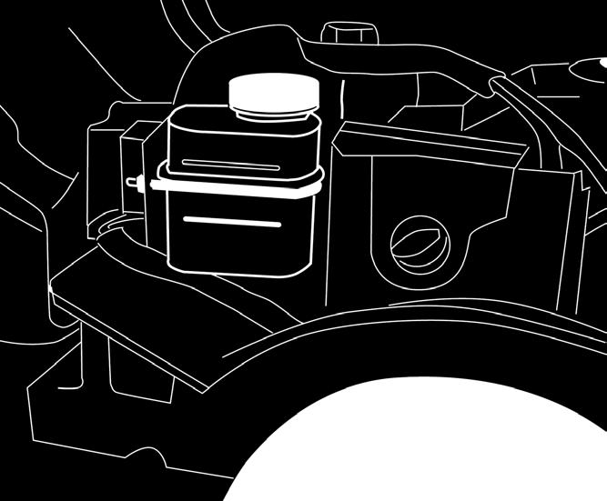
46 EN ENGLISH (Translation of the Original Instructions) 5.4 SEAT (7, 8) 1. Remove the following components from the seat bracket: 4 Nuts (for blocking during transport, not used). 4 Screws (7:K, 8:K). 4 Shoulder washers (7:L, 8:L). 4 Split lock washer (7:R, 8:R). 2. Position the seat on the seat bracket mounting. 3. Put the shoulder washers (7:L, 8:L) on the screws (7:K, 8:K), complete with washers (7:R, 8:R). 4. Insert the screws, complete with shoulder washers, in the slots in the seat bracket and the holes in the seat plate. Screw the seat into place. Tightening torque: 9±1.7 Nm. Tightening the screws to a torque over 9±1.7 Nm, will damaged the seat. 5. Check that the seat moves easily in the slots in the bracket. The seat can be folded. If the machine is parked outside where it is exposed to rain, fold the seat forward to protect the seat cushion from getting wet. 5.5 STEERING WHEEL (9) In order to minimise axial play in the steering column, place the 0.5-mm and/or 1-mm shim/s (3:C, 3:B) on the steering column between the sleeves (9:A) as follows: 1. Install the sleeve (9:B) on the steering column and secure in place by inserting one of the pins (9:C) by approximately 1/3 of its length. 2. Pull the sleeve and steering column upwards. 3. Check that the 0.5-mm shim, the 1.0-mm shim (or both) can be inserted into the gap which is created in point (9:A). The shim/s must not be forced in, as there must be a little axial play. 4. Remove the pin (9:C) using a pin punch (9:D) and remove the sleeve. 5. Install the shim/s as indicated in point 3 above. 6. Install the sleeve on the steering column and secure by inserting both pins completely. Block the steering column. 5.6 TOW BAR (10) Install the tow bar (10:B) on the rear of the machine. Use the screws and nuts (10:A, 10:C). Tightening torque: 22 Nm. 5.7 ARM RESTS - MODELS: [4WD] (11) The armrests and relative fasteners needed for their installation are provided in a separate package. 5.8 QUICK-RELEASE SUPPORTS (1:N) The quick-release supports and relative installation instructions are supplied in a separate package. Install the quick-release supports on the machine s front axles. 5.9 TYRE PRESSURE For the tyre pressure, please refer to 0 TECHNI- CAL DATA TABLE ACCESSORIES For installation of accessories, see the installation guide accompanying each accessory. Note: In this case the cutting means assembly is considered an accessory. 6 CONTROLS 6.1 ACOUSTIC SIGNALLING DEVICE Indicates a lack of pressure in the engine s hydraulic circuit. When the acoustic signal is also active with the engine running, turn off the engine and check/top up the fluid level (25:A). When the acoustic signal sounds: With the clutch-parking brake pedal (12:B) released and the ignition key (13:C, 14:C) in the operating position In rare cases when engine revs are too low meaning there is insufficient pressure in the hydraulic system. How to deactivate it: Press the clutch-parking brake pedal (12:B) all the way down. This is useful above all in the engine starting phase to avoid setting the acoustic signal off. 12
47 (Translation of the Original Instructions) ENGLISH EN 6.2 MECHANICAL ACCESSORY LIFT PE- DAL [2WD] (12:C) The control lever (12:C1)is used to take the accessories from the operating position to the transport position. Transport position: press the pedal right down then lift your foot off: the pedal stays down. Operating position: press and slowly release the pedal. Do not attempt to switch to the transport position while the hooked-up accessory is in operation. This will destroy the drive belt. 6.3 ACCESSORY LIFTING DEVICE, HYDRAULIC [4WD] (14:H) The hydraulic accessories lifting device is active only when the engine is running and pedal (12:B) is released. The accessories lifting device is controlled by a lever (14:H). The lever can be in one of the four following positions: Floating positions. Move the lever to the most forward position, where it stops At this point the accessory is lowered to the floating position. In this position, it is always resting on the ground exerting the same pressure and can follow the profile of the terrain. Use the floating position when performing work. Lower position. The accessory is lowered. Standby position (central). After lifting or lowering, the lever returns to the standby position. The accessory holds the position of the last command executed. Lift position. Move the lever to the furthest back position until the accessory has reached the highest position (transport position). Then release the lever: the accessory remains blocked in the transport position. 6.4 PARKING BRAKE PEDAL (12:B) Note: When the pedal is approximately at the halfway point of its stroke, forward traction is disengaged and the parking brake is deactivated. the power transmission. Il The pedal (12:B) has the following three positions: Released: Traction is engaged. The parking brake is not activated. Pressed to halfway: Forward drive disengaged. The parking brake is not activated. Pressed right down. Forward drive disengaged. The parking brake is fully activated but not locked. This position is also used as an emergency brake. 6.5 PARKING BRAKE LOCKING LEVER (12:A) The lever locks the clutch-brake pedal in the pressed right down position. This function is used to lock the machine on slopes, during transport, etc., when the engine is not running. Locking: 1. Press the pedal (12:B) right down. 2. Move the locking lever (12:A) upward. 3. Release the pedal (12:B). 4. Release the locking lever (12:A). Unlocking: Press and release the pedal (12:B). 6.6 TRACTION PEDAL (12:F) If the machine does not brake as expected when the pedal is released, use the left pedal (12:A) as an emergency brake. The pedal determines the gearing ratio between the engine and the drive wheels (= the speed). When the pedal is released, the service brake is activated. - Press the pedal forward the machine moves forward. - No load on the pedal the machine is stationary. - Press the pedal backward the machine reverses. Reduce the pressure on the pedal the machine brakes. A plate is installed on the upper section of the pedal which can be adjusted to suit the driver s foot. Never partially press the pedal while driving. There is a risk of overheating 13
48 EN ENGLISH (Translation of the Original Instructions) 6.7 STEERING WHEEL (12:D) The height of the steering wheel is fully adjustable. Unscrew the adjustment knob (12:E) on the steering column and raise or lower the steering wheel accordingly. Tighten. Do not adjust the steering wheel when the machine is running. Never turn the steering wheel when the machine is stationary with a lowered accessory. There is a risk of abnormal loads on the servo and steering mechanisms. 6.8 THROTTLE CONTROL (ACCELERATOR) (13:A) Control for regulating engine running speed. 1. Full throttle should always be used when the machine is in use. 2. Idling. 6.9 HEADLAMPS CONTROL (13:B, 14:B) Pull-out control for turning the headlamps on and off. Start-up: pull the knob (13:B, 14:B) up, pos. B1. Switching off: Push the knob (13:B, 14:B) down, pos. B IGNITION BLOCK (13:C, 14:C) The ignition block is used for starting and stopping the engine. Do not leave the ignition key in position 2 or 3 when you leave the driving seat. There is a risk of fire (fuel can run into the engine through the carburettor) and the battery may go flat and get damaged. The four ignition key positions: 1. Stop position the engine is short-circuited. The key can be removed. 2. Function not present, see (13:B, 14:B) 3. Operating position. 4. Start position the electric starter motor is activated when the key is turned to this position. Once the engine has started, let go of the key which will return to operating position POWER TAKE-OFF (13:D, 14:D) Switch for engaging and disengaging the electromagnetic PTO used to activate front-mounted accessories. The PTO must never be engaged when the front accessory lift is in the transport position. This will destroy the belt drive. The switch has two positions: 1. Engaged - to engage the PTO press the front part of the switch. If the light is on it means the PTO is engaged. 2. Disengaged - to disengage the PTO press the rear part of the switch. If the light is off it means the PTO is disengaged HOUR METER (15:B) Indicates the number of service hours completed. Only works when the engine is running CUTTING HEIGHT ADJUSTMENT [4WD] (13:E, 14:E) The machine is equipped with a control for using the cutting device with electrical cutting height adjustment. The switch allows the user to continuously adjust the cutting height. The cutting means are connected to the contact (14:A) TRANSMISSION RELEASE LEVER (16, 17) A lever for disengaging the variable transmission. Model [2WD] Is equipped with a lever, connected to the rear axle. See (16:A). Model [4WD] Is equipped with two levers (17:A, 17:B)) connected to the rear and front axle respectively. The engagement/release lever must never be between the outer and inner positions. This overheats and damages the transmission. 14
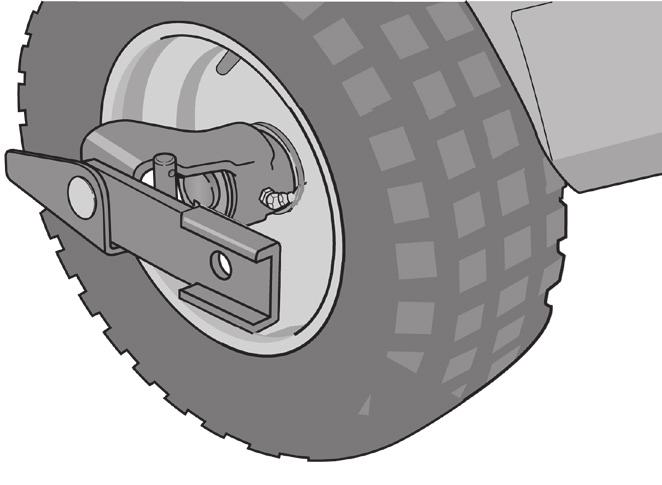
49 (Translation of the Original Instructions) ENGLISH EN The levers allow the user to move the machine manually (pushing or pulling), without the engine running. The two positions are: 1. Transmission engaged = lever in. For normal use. 2. Transmission disengaged = lever out. The machine can be moved by hand. The machine must not be towed over long distances or at high speeds. The transmission could get damaged. Do not activate the machine with the transmission disengaged (lever out). Risk of damage and oil leakage in the front axle SEAT ADJUSTMENT (18:B) The seat is foldable and can be moved backwards and forwards to suit the driver as indicated below: 1. Move the control lever (18:A) upwards. 2. Set the seat to the desired position. 3. Release the control lever (18:A) to lock the seat. The seat is equipped with a safety switch that is connected to the machine s safety system. This means that when no-one is sitting in the seat the machine cannot be started.(see 7.7.2) BONNET It is prohibited to start the engine when the bonnet is open. WARNING: When the bonnet is open there is a risk of burns, abrasions and crushing injuries. To open the bonnet, see QUICK-RELEASE SUPPORTS These support allows the user to swap from one accessory to another quickly and easily. The quick-release supports allow the user to move the cutting device quickly and easily between two positions, i.e.: Normal position with the belt fully tensioned. Positioned 4 cm behind the normal position, with the belt slackened, so that the cutting device moves closer to the base of the machine. Being as the belt tensioner is released from the belt, the quick-release supports simplify belt and cutting device replacement, and also make shifting to the washing position and service positions easier. Belt tension releasing (19, 21) See also the instructions provided with the accessory and with the quick-release support. 1. Remove the cotter pins or lock pins (19:C) from both sides. 2. Open the quick-release supports by pressing on their rear sections with your heel ((19:A) Once the quick-release supports have been opened, the arms of the accessory are free and no longer secured to the hook-up device. For any adjustment or maintenance operation, replace the arms on the support and reclose. 3. Carry out the necessary corrective action, e.g.: Release the belt. Replace the accessory by unhooking the arms (21). Tensioning the belt (19, 20) First tension one side and then the other according to the instructions provided below. Do not turn the lever using your hands. Risk of crushing injuries. 1. Place your foot on the lever (20:A) and carefully turn it 180 forwards. 2. Install the cotter pin or lock pin (19:C). 3. Repeat the operation on the other side. 7 START-UP AND OPERATION 7.1 PRECAUTIONS FOR USE Always make sure the engine oil level is correct. This is particularly important when operating on slopes (see 9.9.1). 15
50 EN ENGLISH (Translation of the Original Instructions) Be very careful when cutting grass on slopes: avoid abrupt starts and stops, do not run the machine transversally to the slope but run from top to bottom and vice versa. Apply the parking brake when you park the machine. The machine may not be driven on slopes greater than 10º in any direction. Reduce the speed on slopes and when making sharp turns in order to retain control of the machine and reduce the risk of overturning. Do not turn the steering wheel to full lock when driving at full speed. The machine may overturn. Keep hands and feet well away from the articulated steering joint and seat bracket. Risk of crushing injuries. 7.2 COMBINED USE OF ACCESSORIES For the combined use of accessories, please refer to the TABLE FOR THE CORRECT COMBINATION OF ACCES- SORIES in section 0 TECHNICAL DATA TABLE 7.3 REFUELLING Use only the prescribed types of fuel. For the capacity of the fuel tank and the type of fuel to be used, please refer to 0 TECHNICAL DATA TABLE. The transparency of the tank allows the user to check the level easily. Do not use rapeseed-based biodiesel (RME). NOTE! Further information on the type of fuel to be used can be obtained from the engine supplier. Filling the fuel tank over the MAX level indicated in fig. 23 will lead to fuel leaks and fire hazards. Fuel increases in volume when it heats up. 2. Open the fuel cap (23:A). 3. Fill with fuel up to the MAX level. 4. Close the fuel cap. Temperatures below 0 C. Use winter fuel or add kerosene when the ambient temperature drops below 0 C For the quantity of kerosene to mix with the fuel, adhere to the parameters provided in the table below. Ambient operating temperature in C Quantity of kerosene to be added Summer fuel Winter fuel From 0 to % - From -10 to % - From -15 to % 20 % From -20 to % 7.4 FUEL CIRCUIT PRIMING Prime the fuel circuit in the following cases: When the fuel tank has run dry or air has got into the fuel circuit. After replacing the filter. To prime the circuit: 1. Fill the fuel tank. 2. Pump the hand pump (24:A) to send fuel through the transparent filter (24:B) until it is almost full (usually 4 or 5 pumping actions suffice). 7.5 CHECKING THE ENGINE OIL LEVEL (25) The machine is delivered complete with engine oil. Before starting the machine check the level of the engine oil. To check / top up the engine oil, see CHECKING THE TRANSMISSION FLUID LEVEL To check / top up the transmission fluid, see To fill up with fuel: 1. Open the bonnet (see 5.2). 16
51 (Translation of the Original Instructions) ENGLISH EN 7.7 SAFETY CHECKS When trying out the machine, check that the results of the safety checks correspond with the indications provided in the following tables. Always carry out the safety checks before use. If any of the results fails to match the indications provided in the following table, do not use the machine! Take it to a service centre to be checked and repaired if necessary General safety check Object Fuel lines and connections. Electrical cables. Exhaust system. Engine supports Oil lines Drive the machine forwards/ backwards and release the drivingservice brake pedal. Test driving Result No leaks Electrical safety check All insulation intact. No mechanical damage. No leaks at connections. All screws tightened. The bolts which secure the engine to the supports are correctly tightened. No leaks. No damage. The machine will stop. No abnormal vibrations. No abnormal sound. Status Action Result The clutch-brake pedal is not pressed. The PTO is not activated. Engine running. Try to start the machine. The driver gets up from the seat. The engine will not start. The engine is switched off. The clutch-brake pedal is not pressed. The ignition key is in the operating position. The acoustic signalling device is active. 7.8 START-UP / OPERATION Press the clutch-brake pedal. Start the engine and take it up to operating speed. The signal switches off. When using the machine, the bonnet must be closed and fastened shut. Always use full throttle when using the machine Start-up 1. Activate the parking brake (12:B) 2. Check that the battery cables are correctly connected. 3. Engage the transmission (16:A) (17:A, 17:B) - (lever in). 4. Sit in the driving seat. 5. Keep the service brake/drive pedal free (12:F). 6. Turn the throttle to full on (13:A, 14:A) 7. Turn the ignition key to the operating position, see Disengage the PTO (13:E, 14:E). 9. Turn the key in the ignition to the start engine position and start the engine. Before starting work with the machine when the engine is cold and particularly when the ambient temperature is 0 C or less, wait a few minutes for the oil to warm up. Always use full throttle when using the machine Operation To work with the machine: Press the pedal (12:B) right down then release it. Activate the pedal (12:F) to move the machine. Go to the work area. If front accessories have been installed, activate the PTO (12:E - 13:E) Commence work. 17
52 EN ENGLISH (Translation of the Original Instructions) Power steering The steering wheel is fitted with a mechanism connected to the machine s hydraulic circuit for easier steering. When the engine is running at minimum speed, use of the steering wheel may become stiffer as the pressure in the hydraulic circuit drops. 7.9 STOPPING To stop the machine: Disengage the PTO (13:D, 14:D). Engage the parking brake (12:B). Turn off the engine by turning the ignition key. 18 If you have to leave the machine unattended remove the key from the ignition. The engine may be very hot just after it has been switched off. Do not touch the silencer, the engine or the cooling fins. Burns hazard CLEANING To reduce the risk of fire, keep the engine, silencer, battery and fuel tank free from grass, leaves and oil. To reduce the risk of fire, regularly check the machine for oil and/or fuel leaks. Never use high-pressure water jets. This can damage shaft seals, electrical components or hydraulic valves. Always clean the machine after use. To clean the machine adhere to the instructions provided below: Do not spray water directly onto the engine. Clean the engine with a brush and/or compressed air. Clean the motor cooling air intake. After cleaning using water, start the machine and any cutting means assembly to remove any water which may otherwise end up in the bearings and cause damage. 8 USING THE ATTACHMENT Make sure the grass to be cut is completely free of foreign objects such as stones etc. 8.1 CUTTING HEIGHT For best results, cut off the top third of the grass. See fig. 22. If the grass is long and needs cutting back significantly, cut twice using two different cutting heights. Do not use the lowest cutting heights if the lawn surface is uneven. This would entail a risk of the cutting devices being damaged against the surface and the lawn s top layer of soil being removed. 8.2 MOWING TIPS To get the best mowing results, follow the tips given below. Cut grass frequently. Run the machine at full revs. Grass should not be wet. Use sharp cutting means. Keep the bottom side of the cutting device clean. 9 MAINTENANCE 9.1 ASSISTANCE PROGRAMME To keep the machine in good working order in terms of reliability, safety and environmental protection, always adhere to the STIGA SpA servicing programme. The points of intervention for this programme are illustrated in the attached STIGA SpA maintenance manual. The Basic Service must always be carried out by an authorized service workshop. The First Service and Intermediate Service should be carried out by an authorized service workshop, but can also be carried out by the user. The procedures are indicated in the handbook and are described in the chapter 7 START-UP AND OPERATION as well as here below. The checks carried out by an authorized service workshop guarantee professional workmanship and the use of genuine spare parts. The handbook is stamped every time a Basic Service is performed and each time an Intermediate Service is carried out by an authorized service workshop. A handbook with these stamps increases the second-hand value of the machine.
53 (Translation of the Original Instructions) ENGLISH EN 9.2 PREPARATION All service and all maintenance checks must be carried out on a stationary machine with the engine switched off. Always apply the parking brake to stop the machine from moving. Stop the engine. Prevent inadvertent start-up of the engine by disconnecting the spark plug cables and removing the ignition key. 9.3 MAINTENANCE TABLE See chapter 13 MAINTENANCE SUM- MARY TABLE. The table is designed to help you keep your machine in efficient and safe working order. It indicates the main operations to be performed and the frequency of the same. Perform the relative operation described based on the first deadline to arrive. Change the oil more frequently if the engine has to work in difficult conditions or when the ambient temperature is high. 9.4 TYRE PRESSURE Adjust the tyre pressure to meet the values provided in 0 TECHNICAL DATA TABLE. 9.5 ENGINE OIL TOP-UP/CHANGE For this maintenance operation, see also the manual for the engine supplied with the machine Check / top-up (25) Always check the oil level before use. To check the level, make sure the machine is on even ground. Wipe around the dipstick Remove the dipstick and clean. Push the dipstick in completely. Now pull the dipstick up again. Read off the oil level. Top up if the level is lower than the FULL mark (25). The oil level must never exceed the MAX mark. This results in the engine overheating. If the oil level exceeds the MAX mark, the oil must be drained until the correct level is achieved Oil change/filling (25, 26) For the frequency of this intervention see chapter 13. For the type of oil to use please refer to 0 TECHNICAL DATA TABLE. Use oil with no additives. NOTE! Do not overfill as this could cause the engine to overheat. Change the oil when the engine is warm. The oil may be very hot just after the engine has been switched off. Consequently allow the engine to cool down for a few minutes before proceeding to drain off the oil. Proceed as follows: 1. Place the machine on a flat surface. 2. Apply the parking brake. 3. Open the bonnet. 4. Remove the oil drain tube (26:A) from the vertical position, slip it between the frame and the engine and take it downwards. 5. Grab the clamp on the oil drain hose. Use polygrip pliers or similar (26:B). 6. Move the clamp 3-4 cm up the oil drain hose and pull out the plug (26:C). 7. Collect the oil in a suitable vessel. NOTE! Take care not to spill any oil on the drive belts. 8. Hand the spent oil over to a disposal facility in accordance with local provisions. 9. Replace the oil drain plug and move the clamp back over the plug. 10. Clean up any spills. 11. Remove the oil cap (25:A) and fill with new oil. For the quantities of oil required, please refer to 0 TECHNICAL DATA TABLE. 12. After filling up the oil, start the engine and leave it to idle for 30 seconds. 13. Check there are no oil leaks. 14. Turn off the engine. Wait 30 seconds and check the oil level again. If necessary see also checking/top up in heading
54 EN ENGLISH (Translation of the Original Instructions) Oil filter For the frequency of this intervention see chapter 13. To clean the oil filter: 1. Clean the area around the filter (27:A). 2. Slacken the screw (27:B) and unscrew by 5 turns. 3. Extract the oil filter Never aim jets of compressed air at or close to the body. Air penetration into the blood flow can be fatal. 4. Clean the filter by blowing compressed air into and over the outside of the filter. See fig Check/replace the seals (28:A). 6. Lubricate the seals (28:A). 7. Insert the filter in its seat and slide it all the way in. 8. Check that the ends of the tensioner spring (27:C) are flush with the filter. 9. Screw in and tighten the screw (27:B). 10. Proceed with point 10 of the previous heading CHECK/TIGHTEN ENGINE SUPPORT SCREWS AND VIBRATION ABSORBERS (40) Inspect the engine support screws (40:A) and the vibration absorbers wear (40:B), checking that the motor does not have abnormal vibrations. For the frequency of this intervention see chapter 13. Do not touch the cylinder head screw or the injection system adjustment screw. For any problems concerning these parts, contact a Service Centre. 9.7 REPLACING THE FUEL FILTER (24) For this maintenance operation, see also the manual for the engine supplied with the machine. For the frequency of this intervention see chapter 13. After the replacement, prime the fuel circuit (see 7.4). Check for fuel leaks once the new filter has been installed. 9.8 FUEL TANK CONDENSATE DRAINAGE (30) Changes in temperature can lead to the formation of condensation in the fuel tank. The quantity of condensation increase when there are significant changes in temperature and in the presence of a high level of humidity. Water is deposited on the bottom of the fuel tank. For the frequency of this intervention see chapter 13. Drain of the condensate when the engine is cold. When the engine is warm there is a risk of fire. During operations to drain off the condensate it is forbidden to smoke, light fires, create sparks and position heat sources in the near vicinity. Fire hazard! To drain off the condensate: 1. Open the bonnet and stand behind the machine. 2. Grab the clamp (30:A) on the drain hose (30:B). Use adjustable polygrip pliers or similar. 3. Move the clamp 3-4 cm up the drain hose and pull out the plug (30:C). 4. Place a suitable vessel under the hose. 5. Open the drain valve (30:D) and drain off the condensate. 6. Close the drain valve. 7. Restore the original positions of the plug and clamp. 8. Hand the drained liquid to a disposal facility in accordance with local provisions. 9.9 CHECKING/CHANGING THE TRANSMISSION FLUID For the frequency of this intervention see chapter 13. For the type of oil to use please refer to 0 TECHNICAL DATA TABLE Check/top-up (31, 32) 1. Place the machine on a flat surface. 2. Check the fluid level in the reservoir (31:A, 32:A). The level should approximately reach the MAX line as shown in the figure. 3. Top up if necessary Draining off spent fluid [4WD] 1. Run the machine at variable speeds for minutes to heat up the transmission fluid. 2. Place the machine on a flat surface. 20
55 (Translation of the Original Instructions) ENGLISH EN 3. Apply the parking brake. 4. Disengage the transmission - lever (17:A, 17:B) out (pos. A1, B1). 5. Place a container under the rear axle and another one under the front axle. For the fluid drain plug on the rear axle, use a wrench with a 3/8 square connection only. Any other tool may damage the plug. 6. Remove the fluid drain plug from the rear axle (33:A). 7. Remove the 2 drain plugs (34) on the front axle. Use a 12 mm tubular wrench. Allow the fluid in the front axle and pipes to drain out. 8. Open the bonnet and remove the plug (31:B) on the transmission fluid reservoir. 9. Let the fluid run out into suitable containers. 10. Draw out the fluid from the deepest part of the reservoir using a fluid extractor (35). 11. Check that the gaskets on the drain plugs of the front axle are intact (34). Replace the plugs. Tightening torque: Nm. 12. Check that the gasket on the drain plug of the rear axle is intact (33:A). Replace the plug in the rear axle. Tighten the drain plug to a torque of 5 Nm. The drain plug might get damaged if it is tightened to a torque exceeding 5 Nm. 13. Dispose of the oil according to local regulations Fluid filling [4WD] NOTE! The oil is drawn into the system very quickly. The tank must be filled up in a continuous manner until it remains full in order to fill the circuit and make sure air is not drawn into the system (something which must never be allowed to happen). 1. Prepare a suitably large vessel full of fresh fluid. 2. Fill the fluid reservoir with fresh fluid. For the quantities and type of fluid required, please see 0 TECHNICAL DATA TABLE. 3. Check that the rear drive s release lever is disengaged, lever (17:A) out. Place two wooden planks (4-5 cm thick) in front of the rear wheels (so they are touching the tyres)to make sure the machine stays stationary during the following operations. 4. Release the parking brake. Press the pedal (12:B) right down and then release. WARNING: the following operations must be performed with the engine bonnet open and the engine running. Keep hands well away from moving parts. If the engine is run indoors, exhaust extraction equipment must be connected to the engine s exhaust pipe. 5. Start the engine. Never start the engine when the rear axle clutch release lever is engaged and the front axle clutch release lever is disengaged. This could damage the front axle gaskets. 6. Disengage the front axle s clutch release lever. 7. Set the accelerator pedal to the forward position, locking it using a wooden wedge (36). Gradually pour fluid into the reservoir and make sure that the level is always between the MIN and MAX mark. 8. Run in the forward position for one minute. 9. Move the wooden wedge and set the accelerator pedal to the reverse position. Continue filling with oil. 10. Run in reverse mode for one minute. 11. Change driving direction every minute as indicated above and continue filling with oil until the bubbling in the reservoir stops. 12. Switch off the engine, replace the cover (31:B) on the fluid tank and close the bonnet. 13. Move the 2 levers (17:A, 17:B) for engaging the transmission to the operating position (= in). 14. Restart the engine. 15. Move the machine at various speeds for a few minutes. At the same time turn the steering wheel completely several times. 16. Lift and lower the hydraulic accessories lifting device 3-4 times. 17. Stop the machine and put the parking brake back on. 18. Open the bonnet. 19. Check the level in the reservoir and top up if necessary. 20. Once the operation has been completed, replace the fluid cap and close the bonnet. 21
56 EN ENGLISH (Translation of the Original Instructions) 9.10 BELT TRANSMISSIONS CHECK check that all belts are intact. For the frequency of this intervention see chapter STEERING For the frequency of this intervention see chapter Checks Gently turn the steering wheel back and forth. There must be no mechanical play in the steering chains Adjustment (37) Adjust the steering chains if required as follows: 1. Put the machine in the straight-ahead position. 2. Adjust the steering chains by means of the two nuts, located under the central point (37:A). 3. Adjust both nuts by the same amount until there is no play. 4. Test drive the machine, moving it forward in a straight line and checking that the steering wheel is not off centre. 5. If the steering wheel is off centre, slacken one nut and tighten the other. Do not over tension the steering chains. This would make the steering too stiff and increase wear on the chains BATTERY For the type of battery installed on the machine, please refer to 0 TECHNICAL DATA TABLE CAUTION! Battery acid is corrosive and contact with it is harmful. Handle the battery with care taking care not to let acid leak out. Acid can cause serious injuries if it comes into contact with eyes or skin. If any part of the body comes into contact with acid, rinse immediately with copious amounts of water and seek medical attention immediately. The battery fluid does not need checking or topping up. The only maintenance operation required is charging, for example after extended storage. The battery can be charged: by the engine, by a battery charger Charging by the engine This method is only an option if there is still enough charge in the battery to be able to start the engine. If the battery is new, connect the relative leads. Take the machine outside. Start the engine by following the instructions provided in this manual. Leave the engine running continuously for 45 minutes (the time needed to fully charge the battery). Turn off the engine Charging with a battery charger Use a constant voltage battery charger. Use of a standard charger may damage the battery. For further information, please contact your dealer. Before connecting the battery charger, disconnect the battery from the electrical system Disassembly/assembly The battery is housed under the bonnet. During removal/installation of the battery, connect and disconnect the leads as follows: During removal. First disconnect the black lead from the battery s negative terminal (-). Then disconnect the red lead from the battery s positive terminal (+). During installation. First connect the red lead to the battery s positive terminal (+). Then connect the black lead to the battery s negative terminal (-). If the leads are disconnected/connected in the wrong order, there is a risk of a short-circuit and damage to the battery. If the leads are interchanged, the alternator and the battery may be damaged. 22
57 (Translation of the Original Instructions) ENGLISH EN Tighten the leads securely. Loose leads are a fire risk. Never start the engine with the battery disconnected. There is a risk of serious damage to the alternator and the electrical system Cleaning / Replacement For the frequency of this intervention see chapter 13. If the battery terminals are coated with oxide, they should be cleaned. Clean the battery terminals with a wire brush and lubricate them with terminal grease AIR FILTER, ENGINE For the frequency of this intervention see chapter 13. For this maintenance operation, see also the manual for the engine supplied with the machine Cleaning / Replacement (38, 39) For the frequency of this intervention see chapter 13. A damaged air filter will allow contaminated air into the engine. This can seriously damage the engine.. NOTE! The filters should be cleaned/replaced more often if the machine operates on very dusty ground. Remove/install the air filters as follows: 1. Apply the parking brake. 2. Open the bonnet. 3. Remove the rear right mudguard (38:A), unscrew and remove the two wing nuts (38:B) and relative plastic washers (38:C). 4. Clean around the air filter cover (38:D). 5. Slacken and remove the knob (38, 39:E). 6. Take of the filter cover (38, 39:D). 7. Unscrew the knob (39:F) and remove the filter (39:G). Never aim jets of compressed air at or close to the body. Air penetration into the blood flow can be fatal. 8. Remove any dry dirt by blowing compressed air into and over the outside of the filter. The pressure must not exceed 5 bar. 9. After cleaning, check that there are no breakages or other damage. This can be done holding the filter up against the light and visually checking its condition. 10. Check that the filter s coupling surfaces are free from defects. 11. If the filter is damaged or contaminated with humidity and/or oily dirt it must be replaced. 12. Reassemble by following the instructions in reverse order. Compressed air or petroleum-based solvents such as kerosene must not be used for cleaning the paper filter insert. This will damage the filter Cleaning the air intake. For the frequency of this intervention see chapter 13. See figure (24:C). The engine is air-cooled. A blocked cooling system can damage the engine. Clean the engine s air intake after 50 service hours. More meticulous cleaning of the cooling system should be carried out during each basic service LUBRICATION (41) For the frequency of this intervention see chapter 13. All lubrication points indicated in the table below must be lubricated every 50 service hours and after every wash. Object Action Fig. Wheel bearings Only for model 4WD Centre point Steering chains Tensioning arms 2 grease nipples Use a grease gun filled with universal grease. Pump until the grease seeps out. 4 grease nipples Use a grease gun filled with universal grease. Pump until the grease seeps out. Brush the chains clean with a wire brush. Lubricate with universal chain spray. Lubricate the support points with oil when each control is activated. 41:A 41:B 41:C 41:D 23
58 EN ENGLISH (Translation of the Original Instructions) Control cables Machines with quickrelease supports Lubricate the cable ends with oil when each control is activated. This operation must be carried out by two people. 1 grease nipple Use a grease gun filled with universal grease Pump until the grease seeps out Fuses (42, 43) 41:E 41:F If any of the faults listed below occurs, replace the relevant fuse (42, 43). Fault The engine does not start or starts and stops immediately. The battery is charged. The rear accessory and the electrical cutting height adjustment does not work. All electrical functions are out of operation. The battery is charged. Fuse 10 A 20 A 30 A 10 ASSISTANCE AND REPAIRS This manual provides all the necessary information to run the machine and for correct basic maintenance operations which can be performed by the user. Any regulations and maintenance operations not described herein must be carried out by your Dealer or Authorized Service Centre, which have the necessary knowledge and equipment to ensure that the work is carried out correctly, maintaining the correct degree of safety and the original operating conditions of the machine. Before performing any servicing operations: a. Place the machine on a flat surface. b. Apply the parking brake. c. Turn off the engine. d. Remove the key from the ignition. Authorized service workshops carry out guaranteed repairs and maintenance. Always use genuine spare parts. Genuine STIGA SpA spare parts and accessories have been designed specifically for STIGA SpA machines. Please remember that non-genuine spare parts and accessories have not been verified or approved by STIGA SpA. The use of non-genuine spare parts and accessories could adversely affect machine operation and safety. STI- GA SpA shall decline all liability in the event of injuries or damages caused by such parts. Genuine spare parts are supplied by authorized assistance workshops and dealers. It is advisable to send your machine once a year to an authorized service workshop for servicing, assistance and safety device inspection. 24
59 (Translation of the Original Instructions) ENGLISH EN 11 STORAGE 1. Change the oil when the engine is still warm. 2. Thoroughly clean the whole machine. It is particularly important to clean the bottom side of the cutting means assembly. 3. If the paintwork is damaged, touch it up to prevent rust. 4. Place the machine in a covered, dry place. For machines with electric starter: If the storage temperature is correct, simply recharge the batter every four months. Charge the battery before putting the machine into storage. The battery can be seriously damaged it if is put into storage flat. 12 TERMS OF PURCHASE The warranty covers all material and manufacturing defects. The user must follow all the instructions provided in the accompanying documentation. The warranty does not cover damages caused by: failure to become familiar with the documentation accompanying the machine, carelessness, incorrect or prohibited use or assembly, use of non-genuine spare parts, use of accessories not supplied or approved by STIGA SpA. The warranty does not cover: normal wear and tear of consumables, such as drive belts, headlights, wheels, bolts and wires. normal wear and tear engines. Engines are covered by the warranty provided by the relative manufacturer in compliance with the specified terms and conditions. The purchaser is protected by his own national legislation. The purchaser s rights envisaged by the national laws in his own country are not in any way restricted by this warranty. 25
60 EN ENGLISH (Translation of the Original Instructions) Intervention 13 MAINTENANCE SUMMARY TABLE Frequency service hours/calendar months ref. / Ref. Fig. First time Then every MACHINE Check all fasteners - Before each use - Safety checks/check controls - Before each use - Check tyre pressure - Before each use - General cleaning and inspection - At the end of each use - General lubrication - 50 hours and after each 9.14 wash Check the drive belts for wear 5 hours 50 hours 9.10 Check/correct steering 5 hours 100 hours 9.12 Battery charging - Before putting into storage 9.12 For machines with an electric starter: carry out a top-up charge every four months. Cleaning the battery terminals - When there is oxidization ENGINES/TRANSMISSION (general) Check / Top up engine oil - Before each use Replacing / Filling the engine oil 25 hours 250 hours / 12 months Clean the engine oil filter hours, and at every oil change Check / tighten engine support screws - 50 hours / every season 9.6 Check the vibration absorbers wear - 50 hours / every season 9.6 Fuel tank condensate drainage - When necessary 9.8 Replace fuel filter hours / every season 9.7 Checking / filling the transmission oil - 50 hours Replacement / filling the transmission oil 5 hours 200 hours Cleaning Engine Air Filter 25 hours 50 hours Replacing the air filter hours / every season (1) Engine air intake 50 hours 50 hours (1) (1) Clean more frequently when operating in particularly demanding conditions or when there is debris in the air. 26
61 (Translation of the Original Instructions) ENGLISH EN 14 TROUBLESHOOTING Problem Probable cause Remedy 1. The starter motor does not Battery not charged enough. Recharge the flat battery. turn. Battery not connected. Check the connections. Fuse 20A blown. Replace the fuse 2. The starter motor turns but Fuel cock closed. Open the fuel cock. the engine doesn't start. With the ignition key in the No fuel flow. - Check the fuel level in the tank. - Check the fuel filter. start position, the starter motor turns but the engine doesn't start. 3. Difficulty in engine start-up or engine runs irregularly. Carburettor problems. Clean or replace the air filter. 4. Drop in engine performance Forward speed too high in relation Reduce the forward speed and/ during cutting. to the cutting height. or raise the cutting height. 5 The oil buzzer sounds while working. 5. The engine stops for no apparent reason. Problems of engine lubrication. - Fuel tank empty. - Try to restart the engine. - Turn off the machine immediately. - Replace the oil (if the problem persists, contact an authorized service center). Fill the fuel tank (if the problem persists, contact an authorised assistance centre). 6. Uneven cutting. Check the tyre pressure. The cutting device sharpness Contact an authorised assistance centre. level is low. Forward speed too high in Reduce the forward speed and/ relation to the height of the grass or raise the cutting height. being cut. 7. Abnormal vibration during use. 8. With the engine running, activation of the traction pedal does not move the machine. The cutting means assembly is full of grass. - Unbalanced cutting devices. - Slackened cutting devices. - loose components. - possible damage. "Disengage transmission lever in the disengaged position. - Wait for the grass to dry. - Clean the cutting means assembly. Contact an authorised assistance centre for inspection, replacement or repair operations. Engage the transmission. 27
62 EN ENGLISH (Translation of the Original Instructions) Problem Probable cause Remedy If any of the faults listed below occurs, replace the relevant fuse (22). 9. The engine does not start or Fuse 10A blown. Replace fuse 10A. starts and stops immediately. The battery is charged. 10. Electrical cutting height Fuse 20A blown. Replace fuse 20A. adjustment does not work. 11. All electrical functions are out of operation. The battery is charged. Fuse 30A blown. Replace fuse 30A. If problems persist after the operations above have been performed, contact your dealer. Warning! Never attempt to carry out complicated repairs without the necessary tools or technical ability. Any poorly performed interventions will automatically nullify the warranty and exonerate the manufacturer from all liability. 28
63 EXAMPLE
64 NO (Oversettelse av orginal bruksanvisning) FR (Traduction de la notice originale) EN (Translation of the original instruction) DE (Übersetzung der Originalbetriebsanleitung) SV (Översättning av bruksanvisning i original) DA (Oversættelse af den originale brugsanvisning) Déclaration CE de Conformité (Directive Machines 2006/42/CE, Annexe II, partie A) 1. La Société 2. Déclare sous sa propre responsabilité que la machine : Tondeuse à gazon à conducteur assis/ coupe du gazon a) Type / Modèle de Base b) Mois / Année de construction c) Série d) Moteur: moteur essence 3. Est conforme aux prescriptions des directives : e) Organisme de certification f) Examen CE du Type 4. Renvoi aux Normes harmonisées g) Niveau de puissance sonore mesuré h) Niveau de puissance sonore garanti i) Largeur de coupe n) Personne habilitée à établir le Dossier Technique : o) Lieu et Date EC Declaration of Conformity (Machine Directive 2006/42/EC, Annex II, part A) 1. The Company 2. Herby declares under its own responsibility that the machine: ride-on lawnmower with seated operator/ Grass cutting a) Type / Base Model b) Month / Year of manufacture c) Serial number d) Motor: petrol 3. Conforms to directive specifications: e) Certifying body f) EC examination of Type 4. Reference to harmonised Standards g) Sound power level measured h) Sound power level guaranteed i) Range of cut n) Person authorised to create the Technical Folder: o) Place and Date EG-Konformitätserklärung (Maschinenrichtlinie 2006/42/EG, Anhang II, Teil A) 1. Die Gesellschaft 2. Erklärt auf eigene Verantwortung, dass die Maschine: Aufsitzmäher / Rasenschnitt a) Typ / Basismodell b) Monat / Baujahr c) Seriennummer d) Motor: Verbrennungsmotor 3. Den Anforderungen der folgenden Richtlinien entspricht: e) Zertifizierungsstelle f) EG-Baumusterprüfung 4. Bezugnahme auf die harmonisierten Normen g) Gemessener Schallleistungspegel h) Garantierter Schallleistungspegel i) Schnittbreite n) Zur Verfassung der technischen Unterlagen befugte Person: o) Ort und Datum EF- Samsvarserklæring (Maskindirektiv 2006/42/EF, Vedlegg II, del A) 1. Firmaet 2. Erklærer på eget ansvar at maskinen: Sittegressklipper / gressklipping a) Type / Modell b) Måned / Byggeår c) Serienummer d) Motor: forbrenningsmotor 3. Oppfyller kravene i direktivene: e) Sertifiseringsorgan f) EF-typeprøving 4. Henvisning til harmoniserte standarder g) Målt lydeffektnivå h) Garantert lydeffektnivå i) Klippebredde n) Person som har fullmakt til å utferdige teknisk dokumentasjon: o) Sted og dato EG-försäkran om överensstämmelse (Maskindirektiv 2006/42//EG, bilaga II, de la) 1. Företaget 2. Försäkrar på eget ansvar att maskinen Åkgräsklippare / gräsklippning a) Typ / Basmodell b) Månad / Tillverkningsår c) Serienummer d) Motor: förbränningsmotor 3. Överensstämmer med föreskrifterna i direktivet e) Intygsorgan_ Anmält organ f) EG typgodkännande 4. Referens till harmoniserade standarder g) Uppmätt ljudeffektnivå h) Garanterad ljudeffektnivå i) Skärbredd n) Auktoriserad person för upprättandet av den tekniska dokumentationen: o) Ort och datum EF-overensstemmelseserklæring (Maskindirektiv 2006/42/EF, bilag II, del A) 1. Firmaet 2. Erklærer på eget ansvar, at maskinen: Havetraktor/ klipning af græsset a) Type / Model b) Måned / Konstruktionsår c) Serienummer d) Motor: forbrændingsmotor 3. Er i overensstemmelse med specifikationerne ifølge direktiverne: e) Certificeringsorgan f) EF-typeafprøvning 4. Henvisning til harmoniserede standarder g) Målt lydeffektniveau h) Garanteret lydeffektniveau i) Klippebredde n) Person, der har bemyndigelse til at udarbejde det tekniske dossier: o) Sted og dato FI (Alkuperäisten ohjeiden käännös) CS (Překlad původního návodu k používání) NL (Vertaling van de oorspronkelijke gebruiksaanwijzing) ES (Traducción del Manual Original) PT (Tradução do manual original) EG-verklaring van overeenstemming Declaración de Conformidad CE (Richtlijn Machines 2006/42/CE, Bijlage II, deel A) (Directiva Máquinas 2006/42/CE, Anexo II, parte 1. Het bedrijf A) 2. Verklaart onder zijn eigen 1. La Empresa verantwoordelijkheid dat de machine: 2. Declara bajo su propia responsabilidad que la Grasmaaier met zittende bediener / grasmaaier máquina: Cortadora de pasto con conductor a) Type / Basismodel sentado/ Corte hierba b) Maand / Bouwjaar a) Tipo / Modelo Base c) Serienummer b) Mes / Año de fabricación d) Motor: benzinemotor c) Matrícula 3. Voldoet aan de specificaties van de d) Motor: motor de explosión richtlijnen: 3. Cumple con las especificaciones de las e) Certificatie-instituut directivas: f) EG-onderzoek van het Type e) Ente certificador 4. Verwijzing naar de Geharmoniseerde normen f) Examen CE del Tipo g) Gemeten niveau van geluidsvermogen 4. Referencia a las Normas armonizadas h) Gegarandeerd niveau van geluidsvermogen g) Nivel de potencia sonora medido i) Snijbreedte h) Nivel de potencia sonora garantizado n) Bevoegd persoon voor het opstellen van het i) Amplitud de corte Technisch Dossier n) Persona autorizada a realizar el Manual o) Plaats en Datum Técnico: o) Lugar y Fecha EL (Μετάφραση του πρωτοτύπου των οδηγιών TR (Orijinal Talimatların Tercümesi) χρήσης) AT Uygunluk Beyanı EK-Δήλωση συμμόρφωσης (2006/42/CE Makine Direktifi, Ek II, bölüm A) (Οδηγία Μηχανών 2006/42/CE, Παράρτημα II, 1. Şirket μέρος A) 2. Şahsi sorumluluğu altında aşağıdaki 1. Η Εταιρία makinenin: Oturan sürücülü çim biçme makinesi 2. Δηλώνει υπεύθυνα ότι η μηχανή: / çim kesimi Χλοοκοπτικό τρακτέρ με εποχούμενο χειριστή/ a) Tip / Standart model κοπή της χλόης b) Üretimin Ay / yıl a) Τύπος / Βασικό Μοντέλο c) Sicil numarası b) Μήνας / Έτος κατασκευής d) Motor: patlamalı motor c) Αριθμός μητρώου 3. Aşağıdaki direktiflerin özelliklerine uygun d) Κινητήρας: κινητήρας εσωτερικής ανάφλεξης olduğunu beyan etmektedir: 3. Συμμορφώνεται με τις προδιαγραφές της e) Sertifikalandıran kurum οδηγίας: f)... Tipi CE incelemesi e) Οργανισμός πιστοποίησης 4. Harmonize standartlara atıf f) Εξέταση CE του Τύπου g) Ölçülen ses güç seviyesi 4. Αναφορά στους Κανονισμούς εναρμόνισης h) Garanti edilen ses güç seviyesi g) Στάθμη μέτρησης ακουστικής ισχύος i) Kesim genişliği h) Στάθμη εγγυημένης ακουστικής ισχύος n) Teknik Dosyayı oluşturmaya yetkili kişi: i) Εύρος κοπής o) Yer ve Tarih n) Εξουσιοδοτημένο άτομο για την κατάρτιση του Τεχνικού Φυλλαδίου: o) Τόπος και Χρόνος SL (Prevod izvirnih navodil) EY-VAATIMUSTENMUKAISUUSVAKUUTUS Declaração CE de Conformidade (Konedirektiivi 2006/42/EY, Liite II, osa A) (Diretiva de Máquinas 2006/42/CE, Anexo II, 1. Yritys parte A) 2. Vakuuttaa omalla vastuullaan, että kone: 1. A Empresa Päältäajettava ruohonleikkuri / ruohonleikkuu 2. Declara sob a própria responsabilidade que a a) Tyyppi / Perusmalli máquina: Corta-relvas para operador sentado/ b) Kuukausi /Valmistusvuosi corte da relva c) Sarjanumero a) Tipo / Modelo Base d) Moottori : räjähdysmoottori b) Mês / Ano de fabrico 3. On yhdenmukainen seuraavien direktiivien c) Matrícula asettamien vaatimusten kanssa: d) Motor: motor a explosão e) Sertifiointiyritys 3. É conforme às especificações das diretivas: f) EY-tyyppitarkastus e) Órgão certificador 4. Viittaus harmonisoituihin standardeihin f) Exame CE do Tipo g) Mitattu äänitehotaso 4. Referência às Normas harmonizadas h) Taattu äänitehotaso g) Nível medido de potência sonora i) Leikkuuleveys h) Nível garantido de potência sonora n) Teknisten asiakirjojen laatimiseen valtuutettu i) Amplitude de corte henkilö: n) Pessoa autorizada a elaborar o Caderno o) Paikka ja päivämäärä Técnico o) Local e Data MK (Превод на оригиналните упатства) Декларација за усогласеност со ЕУ (Директива за машини 2006/42/CE, Анекс II, дел A) 1. Компанијата 2. изјавува со целосна лична одговорност дека следната машина: Тревокосачка со седнат управувач / косење трева а) Тип / основен модел б) Месец / Година на производство в) етикета г) мотор: мотор со согорување 3. Усогласено со спецификациите според директивите: д) тело за сертификација ѓ) тест СЕ за типот 4. Референци за усогласени нормативи е) Акустички притисок ж) измерено ниво на звучна моќност з) Ниво на гарантирана звучна моќност н) овластено лице за составување на Техничката брошура o) место и датум ES izjava o skladnosti (Direktiva 2006/42/ES), priloga II, del A) 1. Družba 2. pod lastno odgovornostjo izjavlja, da je stroj: Traktorska kosilnica/ košnja trave a) Tip / osnovni model b) Mesec /Leto izdelave c) Serijska številka d) Motor: motor z notranjim izgorevanjem 3. Skladen je z določili direktiv : e) Ustanova, ki izda potrdilo f) ES pregled tipa 4. Sklicevanje na usklajene predpise g) Izmerjen nivo zvočne moči h) Zagotovljen nivo zvočne moči i) Obseg košnje n) Oseba, pooblaščena za sestavo tehnične knjižice: o) Kraj in datum doc_base r.12- ro-fm-p_0 BS (Prijevod originalnih uputa) EZ izjava o sukladnosti (Direktiva o mašinama 2006/42/EZ, Prilog II, deo A) 1. Firma 2. Daje izjavu pod vlastitom odgovornošću da je mašina: Traktorska kosilica (traktorčić) / Košenje trave a) Tip / Osnovni model b) Mjesec / Godina proizvodnje c) Serijski broj d) Motor: motor s unutrašnjim izgaranjem 3. sukladna s osnovnim zahtjevima direktive: e) Certifikaciono tijelo f) EZ ispitivanje tipa 4. Pozivanje na usklađene norme g) Izmjereni nivo zvučne snage h) Garantovani nivo zvučne snage i) Širina košenja n) Osoba ovlaštena za izradu tehničke brošure: o) Mjesto i datum HU (Eredeti használati utasítás fordítása) EK-megfelelőségi nyilatkozata (2006/42/EK gépirányelv, II. melléklet "A" rész) 1. Alulírott Vállalat 2. Felelősségének teljes tudatában kijelenti, hogy az alábbi gép: Vezetőüléses fűnyírógép/ fűnyírás a) Típus / Alaptípus b) Hónap / Gyártás éve c) Gyártási szám d) Motor: robbanómotor 3. Megfelel az alábbi irányelvek előírásainak: e) Tanúsító szerv f) CE vizsgálat típusa 4. Hivatkozás a harmonizált szabványokra g) Mért zajteljesítmény szint h) Garantált zajteljesítmény szint i) Vágási szélesség n) Műszaki Dosszié szerkesztésére felhatalmazott személy: o) Helye és ideje SK (Preklad pôvodného návodu na použitie) ES vyhlásenie o zhode (Smernica o Strojných zariadeniach 2006/42/ES, Príloha II, časť A) 1. Spoločnosť 2. Vyhlasuje na vlastnú zodpovednosť, že stroj: Kosačka so sediacou obsluhou/ kosačka na trávu a) Typ / Základný model b) Mesiac / Rok výroby c) Výrobné číslo d) Motor: spaľovací motor 3. Je v zhode s nariadeniami smerníc: e) Certifikačný orgán f) Skúška typu ES 4. Odkaz na Harmonizované normy g) Nameraná úroveň akustického výkonu h) Zaručená úroveň akustického výkonu i) Šírka kosenia j) Čistý inštalovaný výkon n) Osoba autorizovaná na vytvorenie Technického spisu: o) Miesto a Dátum RO (Traducerea manualului fabricantului) LT (Originalių instrukcijų vertimas) LV (Instrukciju tulkojums no oriģinālvalodas) CE -Declaratie de Conformitate EB atitikties deklaracija EK atbilstības deklarācija (Directiva Maşini 2006/42/CE, Anexa II, partea A) (Mašinų direktyva 2006/42/CE, Priedas II, dalis A) (Direktīva 2006/42/EK par mašīnām, pielikums II, 1. Societatea 1. Bendrovė daļa A) 2. Declară pe propria răspundere că maşina: 2. Prisiima atsakomybę, kad įrenginys: Balninė 1. Uzņēmums Mașină de tuns iarba cu șofer la volan/ tăiat vejapjovė su sėdinčiu operatoriumi / žolės 2. Uzņemoties par to pilnu atbildību, paziņo, ka iarba pjovimas mašīna: Sēžot vadāma zālienu pļaujmašīna/ a) Tip / Model de bază a) Tipas / Bazinis Modelis zāles pļaušana b) Luna /Anul de fabricație b) Mėnuo / Pagaminimo metai c) Număr de serie c) Serijos numeris a) Tips / Bāzes modelis d) Motor: motor cu combustie d) Variklis: vidaus degimo variklis b) Mēnesis / Ražošanas gads 3. Este în conformitate cu specificaţiile 3. Atitinka direktyvose pateiktas specifikacijas: c) Sērijas numurs directivelor: e) Sertifikavimo įstaiga d) Motors: iekšdedzes motors e) Organism de certificare f) CE tipo tyrimas 3. Atbilst šādu direktīvu prasībām: f) Examinare CE de Tip 4. Nuoroda į suderintas Normas e) Sertifikācijas iestāde 4. Referinţă la Standardele armonizate g) Išmatuotas garso galios lygis f) CE tipveida pārbaude g) Nivel de putere sonoră măsurat h) Užtikrinamas garso galios lygis 4. Atsauce uz harmonizētiem standartiem h) Nivel de putere sonoră garantat i) Pjovimo plotis g) Izmērītais skaņas intensitātes līmenis i) Lăţimea de tăiere n) Autorizuotas asmuo sudaryti Techninę h) Garantētais skaņas intensitātes līmenis n) Persoană autorizată să întocmească Dosarul Dokumentaciją: i) Pļaušanas platums Tehnic o) Vieta ir Data n) Pilnvarotais darbinieks, kas sagatavoja o) Locul şi Data tehnisko dokumentāciju: o) Vieta un datums ES Prohlášení o shodě (Směrnice o Strojních zařízeních 2006/42/ES, Příloha II, část A) 1. Společnost 2. Prohlašuje na vlastní odpovědnost, že stroj: Sekačka se sedící obsluhou/ sekačka na trávu a) Typ / Základní model b) Měsíc / Rok výroby c) Výrobní číslo d) Motor: spalovací motor 3. Je ve shodě s nařízeními směrnic: e) Certifikační orgán f) ES zkouška Typu 4. Odkazy na Harmonizované normy g) Naměřená úroveň akustického výkonu h) Zaručená úroveň akustického výkonu i) Šířka řezání n) Osoba autorizovaná pro vytvoření Technického spisu: o) Místo a Datum RU (Перевод оригинальных инструкций) Декларация соответствия нормам ЕС (Директива о машинном оборудовании 2006/42/ЕС, Приложение II, часть A) 1. Предприятие 2. Заявляет под собственную ответственность, что машина: Ездовая косилка с водителем / стрижка газона a) Тип / Базовая модель b) Месяц /Год изготовления c) Паспорт d) Двигатель: двигатель внутреннего сгорания 3. Соответствует требованиям следующих директив: e) Сертифицирующий орган f) Испытание ЕС типового образца 4. Ссылки на гармонизированные нормы g) Измеренный уровень звуковой мощности h) Гарантируемый уровень звуковой мощности i) Амплитуда кошения n) Лицо, уполномоченное на подготовку технической документации: o) Место и дата EXAMPLE PL (Tłumaczenie instrukcji oryginalnej) Deklaracja zgodności WE (Dyrektywa maszynowa 2006/42/WE, Załącznik II, część A) 1. Spółka 2. Oświadcza na własną odpowiedzialność, że maszyna: Kosiarka z operatorem jadącym, w pozycji siedzącej na maszynie/ cięcie trawy a) Typ / Model podstawowy b) Miesiąc / Rok produkcji c) Numer seryjny d) Silnik: silnik o zapłonie iskrowym 3. Spełnia podstawowe wymogi następujących Dyrektyw: e) Jednostka certyfikująca f) Badanie typu WE 4. Odniesienie do Norm zharmonizowanych g) Zmierzony poziom mocy akustycznej h) Gwarantowany poziom mocy akustycznej i) Szerokość cięcia n) Osoba upoważniona do zredagowania Dokumentacji technicznej: o) Miejscowość i data HR (Prijevod originalnih uputa) EK Izjava o sukladnosti (Direktiva 2006/42/EZ o strojevima, dodatak II, dio A) 1. Tvrtka: 2. pod vlastitom odgovornošću izjavljuje da je stroj: Sjedeća kosilica trave s operaterom/ košenje trave a) Vrsta / Osnovni model b) Mjesec / Godina proizvodnje c) Matični broj d) Motor: motor s unutarnjim izgaranjem 3. sukladan s temeljnim zahtjevima direktiva: e) Certifikacijsko tijelo f) Tipsko ispitivanje EZ 4. Primijenjene su slijedeće harmonizirane norme: g) Izmjerena razina zvučne snage h) Zajamčena razina zvučne snage i) Širina rezanja n) Osoba ovlaštena za pravljenje Tehničke datoteke: o) Mjesto i datum SR (Prevod originalnih uputstvai) EC deklaracija o usaglašenosti (Direktiva o mašinama 2006/42/EC, Prilog II, deo A) 1. Preduzeće 2. Daje izjavu pod vlastitom odgovornošću da je mašina: Traktorska kosačica (traktorčić)/ košenje trave a) Tip / Osnovni model b) Mesec /Godina proizvodnje c) Serijski broj d) Motor: motor s unutrašnjim sagorevanjem 3. u skladu s osnovnim zahtevima direktiva: e) Sertifikaciono telo f) EC ispitivanje tipa: 4. Pozivanje na usklađene norme g) Izmereni nivo zvučne snage h) Garantovani nivo zvučne snage i) Širina košenja... n) Osoba ovlašćena za sastavljanje tehničke brošure o) Mesto i datum BG (Превод на оригиналните инструкции) ЕО декларация за съответствие (Директива Машини 2006/42/ЕО, Приложение II, част А) 1. Дружеството 2. На собствена отговорност декларира, че машината: Косачка със седнал водач/ рязане на трева а) Вид / Базисен модел б) Месец / година на производство в) Сериен номер г) Мотор: мотор с вътрешно горене 3. Е в съответствие със спецификата на директивите: д) Сертифициращ орган е) ЕО изследване на вида 4. Базирано на хармонизираните норми ж) Ниво на измерена акустична мощност и) Гарантирано ниво на акустична мощност й) Широчина на косене р) Лице, упълномощено да състави Техническата Документация: o) Място и дата ET (Algupärase kasutusjuhendi tõlge) EÜ vastavusdeklaratsioon (Masinadirektiiv 2006/42/EÜ, Lisa II, osa A) 1. Firma 2. Kinnitab omal vastutusel, et masin: Istuva juhiga muruniitja / muruniitja a) Tüüp / Põhimudel b) Kuu aega / Tootmisaasta c) Matrikkel d) Mootor: Sisepõlemismootor 3. Vastab direktiivide nõuetele: e) Kinnitav asutus f) EÜ tüübihindamine 4. Viide ühtlustatud standarditele g) Mõõdetud helivõimsuse tase h) Garanteeritud helivõimsuse tase i) Lõikelaius n) Tehnilise Lehe autoriseeritud koostaja: o) Koht ja Kuupäev doc_base r.12- ro-fm-p_0
65 by STIGA S.p.A. IT Il contenuto e le immagini del presente manuale d uso sono stati realizzati per conto di STIGA S.p.A. e sono tutelati da diritto d autore E vietata ogni riproduzione o alterazione anche parziale non autorizzata del documento. BG Съдържанието и изображенията в настоящото ръководство са извършени за STIGA S.p.A. и са защитени с авторски права Забранява се всяко неоторизирано възпроизвеждане или промяна, дори и отчасти на документа. BS Sadržaj i slike iz ovog korisničkog priručnika napravljeni su isključivo za STIGA S.p.A. i zaštićeni su autorskim pravima zabranjena je svaka neovlaštena reprodukcija ili izmjena dokumenta, djelomično ili u potpunosti. CS Obsah a obrázky v tomto návodu k použití byly zpracovány jménem společnosti STIGA S.p.A. a jsou chráněny autorským právem Reprodukce či nepovolené pozměňování tohoto dokumentu, a to i částečné, je zakázáno. DA Indhold og illustrationer i denne vejledning er blevet skabt på vegne af STIGA S.p.A. og er beskyttet af ophavsret Enhver gengivelse eller ændring, også delvis, af dokumentet uden autorisation hertil er forbudt. DE Inhalt und Bilder dieser Bedienungsanleitung wurden im Namen von STIGA S.p.A. erstellt und sind urheberrechtlich geschützt Jede nicht genehmigte Vervielfältigung oder Veränderung, auch auszugsweise, dieses Dokuments ist verboten. EL Το περιεχόμενο και οι εικόνες στο παρόν εγχειρίδιο χρήσης δημιουργήθηκαν για λογαριασμό της εταιρείας STIGA S.p.A. και προστατεύονται από πνευματικά δικαιώματα Απαγορεύεται οποιαδήποτε αναπαραγωγή ή τροποποίηση, έστω και μερική, του εγγράφου χωρίς έγκριση. EN The content and images in this User Manual were produced expressly for STIGA S.p.A. and are protected by copyright any unauthorised reproduction or modification to the document, either partially or in full, is prohibited. ES El contenido y las imágenes del presente manual de uso han sido creados por STIGA S.p.A. y están protegidos por los derechos de autor Se prohíbe toda reproducción o modificación, incluso parcial, no autorizada del documento. ET Käesoleva kasutusjuhendi sisu ja kujutised on toodetud konkreetselt ettevõttele STIGA S.p.A. ja neile rakendub autorikaitseseadus dokumendi igasugune osaline või täielik ilma loata reprodutseerimine või muutmine on keelatud. FI Tämän käyttöoppaan sisältö ja kuvat on valmistettu STIGA S.p.A. -yhtiön toimesta ja niitä suojaa tekijänoikeuslaki. Asiakirjan kaikenlainen kopioiminen tai muuttaminen, osittainkin, on kielletty ilman erityistä lupaa. FR Le contenu et les images du présent manuel d'utilisation ont été réalisés pour le compte de STIGA S.p.A. et sont protégés par un droit d'auteur - Toute reproduction ou modification non autorisée, même partielle, du document, est interdite. HR Sadržaj i slike u ovom priručniku za uporabu izrađeni su za tvrtku STIGA S.p.A. te su obuhvaćeni autorskim pravima Zabranjuje se neovlašteno umnožavanje ili prilagodba, djelomična ili u cijelosti, ovog dokumenta. HU Ennek a használati útmutatónak a tartalma és a benne szereplő képek kizárólag a STIGA S.p.A. számára készültek és szerzői joggal védettek tilos a dokumentum bármely részének vagy egészének engedély nélküli sokszorosítása és módosítása. LT Šio naudotojo vadovo turinys ir paveikslėliai skirti tik STIGA S.p.A. ir yra saugomi autorių teisėmis dokumentą atgaminti ar modifikuoti, visiškai arba iš dalies, yra draudžiama. LV Šīs lietotāja rokasgrāmatas saturs un attēli ir veidoti tikai STIGA S.p.A. un ir aizsargāti ar autortiesībām. Jebkāda dokumenta vai tā daļas prettiesiska kopēšana vai pārveide ir stingri aizliegta. MK Содржината и сликите во Упатството за корисникот се подготвени исклучиво за STIGA S.p.A. и се заштитени со авторски права забрането е секое делумно или целосно неовластено репродуцирање или измена на документот. NL De inhoud en de afbeeldingen van deze gebruikshandleiding werden gerealiseerd voor rekening van STIGA S.p.A. en zijn beschermd door het auteursrecht Elke niet-geautoriseerde reproductie of wijziging, ook gedeeltelijke, van het document is verboden. NO Innholdet og bildene i denne brukerveiledningen er utført på oppdrag fra STIGA S.p.A. og er beskyttet ved opphavsrett - Enhver gjengivelse eller endring, selv kun delvis, er forbudt. PL Treść oraz ilustracje zawarte w niniejszej instrukcji obsługi powstały na zlecenie spółki STIGA S.p.A. i są chronione prawami autorskimi Zabrania się wszelkiego kopiowania bądź modyfikowania, także częściowego, niniejszego dokumentu bez uzyskania stosownej zgody. PT As imagens e os conteúdos contidos no presente Manual do Utilizador foram expressamente criados para uso exclusivo da STIGA S.p.A., encontrando-se protegidos por direitos de autor. Qualquer tipo de reprodução ou alteração, parcial ou integral, não autorizadas deste Manual estão expressamente proibidas. RO Conţinutul şi imaginile din manualul de utilizare de faţă au fost realizate în numele STIGA S.p.A. şi sunt protejate de drepturi de autor Este interzisă orice reproducere sau modificare chiar şi parţială neautorizată a documentului. RU Тесты и изображения, содержащиеся в настоящем руководстве, были созданы в интересах STIGA S.p.A. и защищены авторскими правами Любое несанкционированное воспроизведение или изменение документа запрещено. SK Obsah a obrázky v tomto návode na používanie boli spracované menom spoločnosti STIGA S.p.A. a sú chránené autorským právom Reprodukcie či nepovolené pozmeňovanie tohto dokumentu, a to aj čiastočné, je zakázané. SL Vsebine in slike v tem uporabniškem priročniku so izdelane za podjetje STIGA S.p.A. in so zaščitene z avtorskimi pravicami vsakršno nepooblaščeno razmnoževanje ali spreminjanje dokumenta, v celoti ali delno, je prepovedano. SR Sadržaj i slike ovog priručnika za upotrebu su napravljeni u ime STIGA S.p.A. i zaštićeni su autorskim pravima Zabranjena je svaka potpuna ili delimična reprodukcija ili izmena dokumenta bez odobrenja. SV Innehållet och bilderna i denna användarhandbok har framställts för STIGA S.p.A. och skyddas av upphovsrätt all form av reproduktion eller ändring, även partiell, som inte auktoriserats är förbjuden. TR Bu Kullanıcı Kılavuzundaki içerik ve resimler açıkça STIGA S.p.A. için üretilmiştir ve telif hakkı ile korunmaktadır dokümanın izinsiz olarak tamamen ya da kısmen herhangi bir şekilde çoğaltılması ya da değiştirilmesi yasaktır.

66 STIGA S.p.A. Via del Lavoro, Castelfranco Veneto (TV) ITALY
Villa 12 Villa 13 Villa 13 HST Villa 14 HST Villa 16 HST
 Villa series 2WD Villa 12 Villa 13 Villa 13 HST Villa 14 HST Villa 16 HST Type V 301 TOSAERBA CON CONDUCENTE A BORDO SEDUTO SEKAČKA SE SEDÍCÍ OBSLUHOU HAVETRAKTOR/HAVETRAKTOR MED FRONTKLIPPER (FM) AUFSITZMÄHER
Park 120 Park 220. Park series 2WD. Type V 302 Type V 302 S
 Park series 2WD Park 120 Park 220 Type V 302 Type V 302 S TOSAERBA CON CONDUCENTE A BORDO SEDUTO SEKAČKA SE SEDÍCÍ OBSLUHOU HAVETRAKTOR/HAVETRAKTOR MED FRONTKLIPPER (FM) ΧΛΟΟΚΟΠΤΙΚΌ ΤΡΑΚΤΈΡ ΜΕ ΕΠΟΧΟΎΜΕΝΟ
USER'S MANUAL FAN MOTOR DRIVER FMD-02
 USER'S MANUAL FAN MOTOR DRIVER FMD-02 IMPORTANT NOTE: Read this manual carefully before installing or operating your new air conditioning unit. Make sure to save this manual for future reference. FMD Module
UŽIVATELSKÁ PŘÍRUČKA
 UŽIVATELSKÁ PŘÍRUČKA Plni víry a naděje míříme kupředu. S odhodláním zlepšujeme své dovednosti. Zapomeňte na zklamání, ale nikoli na svůj nevyužitý potenciál. Touha překonat sám sebe a dosáhnout hranice
P 520 P 540 PX 720 W 720 PW 740 PWX Type P 901 CH
 Park series 4WD / 2WD 420 420 P 520 P 540 PX 720 W 720 PW 740 PWX Type P 901 CH TOSAERBA CON CONDUCENTE A BORDO SEDUTO SEKAČKA SE SEDÍCÍ OBSLUHOU HAVETRAKTOR/HAVETRAKTOR MED FRONTKLIPPER (FM) AUFSITZMÄHER
P 520 P 540 PX 720 W 720 PW 740 PWX Type P 901 CH
 Park series 4WD / 2WD 420 420 P 520 P 540 PX 720 W 720 PW 740 PWX Type P 901 CH TOSAERBA CON CONDUCENTE A BORDO SEDUTO SEKAČKA SE SEDÍCÍ OBSLUHOU HAVETRAKTOR/HAVETRAKTOR MED FRONTKLIPPER (FM) AUFSITZMÄHER
Villa 12 Villa 13 Villa 13 HST Villa 14 HST Villa 16 HST
 Villa series 2WD Villa 12 Villa 13 Villa 13 HST Villa 14 HST Villa 16 HST Type V 301 TOSAERBA CON CONDUCENTE A BORDO SEDUTO SEKAČKA SE SEDÍCÍ OBSLUHOU HAVETRAKTOR/HAVETRAKTOR MED FRONTKLIPPER (FM) AUFSITZMÄHER
Villa 12 Villa 13 Villa 13 HST Villa 14 HST Villa 16 HST
 Villa series 2WD Villa 12 Villa 13 Villa 13 HST Villa 14 HST Villa 16 HST Type V 301 TOSAERBA CON CONDUCENTE A BORDO SEDUTO SEKAČKA SE SEDÍCÍ OBSLUHOU HAVETRAKTOR/HAVETRAKTOR MED FRONTKLIPPER (FM) AUFSITZMÄHER
2N Voice Alarm Station
 2N Voice Alarm Station 2N Lift1 Installation Manual Version 1.0.0 www.2n.cz EN Voice Alarm Station Description The 2N Voice Alarm Station extends the 2N Lift1/ 2N SingleTalk with an audio unit installed
Izolační manipulační tyče typ IMT IMT Type Insulated Handling Rod
 KATALOG CATALOGUE 024/09/2011 IZOLAČNÍ MANIPULAČNÍ TYČ INSULATED HANDLING ROD TYP IMT KOVOVÁ MANIPULAČNÍ TYČ METALLIC HANDLING ROD TYP KMT ISO 9001:2009 ISO 14001:2005 Izolační manipulační tyče typ IMT
PX. Park series 4WD / 2WD. Type P 901 C 320 W. Type P 901 C W 340 PWX. Type P 901 C 4W
 Park series 4WD / 2WD 320 340 PX Type P 901 C 320 W Type P 901 C W 340 PWX Type P 901 C 4W TOSAERBA CON CONDUCENTE A BORDO SEDUTO SEKAČKA SE SEDÍCÍ OBSLUHOU HAVETRAKTOR/HAVETRAKTOR MED FRONTKLIPPER (FM)
Výukový materiál zpracovaný v rámci operačního programu Vzdělávání pro konkurenceschopnost
 Výukový materiál zpracovaný v rámci operačního programu Vzdělávání pro konkurenceschopnost Registrační číslo: CZ.1.07/1. 5.00/34.0084 Šablona: II/2 Inovace a zkvalitnění výuky cizích jazyků na středních
GUIDELINES FOR CONNECTION TO FTP SERVER TO TRANSFER PRINTING DATA
 GUIDELINES FOR CONNECTION TO FTP SERVER TO TRANSFER PRINTING DATA What is an FTP client and how to use it? FTP (File transport protocol) - A protocol used to transfer your printing data files to the MAFRAPRINT
ROLZ-2. Portable AV/Conference Center. Assembly Instructions
 1 ROLZ-2 Portable AV/Conference Center Assembly Instructions Rolz-2 Portable AV/Conference Center Part Drawing Description Qty Part Drawing Description Qty Hardware List A 1 ½ Flat Head Screw 2 EA P-1
DATA SHEET. BC516 PNP Darlington transistor. technický list DISCRETE SEMICONDUCTORS Apr 23. Product specification Supersedes data of 1997 Apr 16
 zákaznická linka: 840 50 60 70 DISCRETE SEMICONDUCTORS DATA SHEET book, halfpage M3D186 Supersedes data of 1997 Apr 16 1999 Apr 23 str 1 Dodavatel: GM electronic, spol. s r.o., Křižíkova 77, 186 00 Praha
Ministerstvo dopravy České republiky Ministry of Transport of the Czech Republic COMMUNICATION
 Ministerstvo dopravy České republiky Ministry of Transport of the OSV~DČEN( o: Nábřeží L.Svobody 12, CZ-110 15 Praha 1 UDĚLENí HOMOLOGACE RozšlŘENI ~OMOLOGACE ODEJMUTI ~OMOLOGACE UKONČENI VÝROBY COMMUNICATION
Litosil - application
 Litosil - application The series of Litosil is primarily determined for cut polished floors. The cut polished floors are supplied by some specialized firms which are fitted with the appropriate technical
GENERAL INFORMATION RUČNÍ POHON MANUAL DRIVE MECHANISM
 KATALOG CATALOGUE RUČNÍ POHONY PRO VENKOVNÍ PŘÍSTROJE, MONTÁŽ NA BETONOVÉ SLOUPY MANUAL DRIVE MECHANISM FOR THE ACTUATION OF OUTDOOR TYPE SWITCHING DEVICES MOUNTED ON THE CONCRETE POLES TYP RPV ISO 9001:2009
CHAIN TRANSMISSIONS AND WHEELS
 Second School Year CHAIN TRANSMISSIONS AND WHEELS A. Chain transmissions We can use chain transmissions for the transfer and change of rotation motion and the torsional moment. They transfer forces from
Park 120 Park 220. Park series 2WD. Type V 302 Type V 302 S
 Park series 2WD Park 120 Park 220 Type V 302 Type V 302 S TOSAERBA CON CONDUCENTE A BORDO SEDUTO SEKAČKA SE SEDÍCÍ OBSLUHOU HAVETRAKTOR/HAVETRAKTOR MED FRONTKLIPPER (FM) ΧΛΟΟΚΟΠΤΙΚΌ ΤΡΑΚΤΈΡ ΜΕ ΕΠΟΧΟΎΜΕΝΟ
WORKSHEET 1: LINEAR EQUATION 1
 WORKSHEET 1: LINEAR EQUATION 1 1. Write down the arithmetical problem according the dictation: 2. Translate the English words, you can use a dictionary: equations to solve solve inverse operation variable
Uživatelská příručka. USB Charger UCH20
 Uživatelská příručka USB Charger UCH20 Obsah Úvod...3 USB Charger popis... 3 Používání nabíječky USB... 4 Nabíjení zařízení... 4 Právní informace... 5 Declaration of Conformity...6 2 Úvod USB Charger popis
Technické informace Technical book MANITOU MI 15-35
 Technické informace Technical book MANITOU MI 15-35 Vysokozdvižné vozíky, pohon: nafta / plyn Forklift trucks, diesel / gas MI 20-25 MI 30-35 Ostatní Misc. Motor Engine Výkony Performances Rozměry Dimensions
Uživatelská příručka. Xperia P TV Dock DK21
 Uživatelská příručka Xperia P TV Dock DK21 Obsah Úvod...3 Přehled zadní strany stanice TV Dock...3 Začínáme...4 Správce LiveWare...4 Upgradování aplikace Správce LiveWare...4 Použití stanice TV Dock...5
1-AYKY. Instalační kabely s Al jádrem. Standard TP-KK-133/01, PNE 347659-3. Konstrukce. Použití. Vlastnosti. Installation cables with Al conductor
 Instalační kabely s Al jádrem Installation cables with Al conductor Standard TP-KK-133/01, PNE 347659-3 4 3 2 1 Konstrukce Construction 1 Hliníkové jádro Aluminium conductor 2 Izolace PVC 3 Výplňový obal
FIRE INVESTIGATION. Střední průmyslová škola Hranice. Mgr. Radka Vorlová. 19_Fire investigation CZ.1.07/1.5.00/
 FIRE INVESTIGATION Střední průmyslová škola Hranice Mgr. Radka Vorlová 19_Fire investigation CZ.1.07/1.5.00/34.0608 Výukový materiál Číslo projektu: CZ.1.07/1.5.00/21.34.0608 Šablona: III/2 Inovace a zkvalitnění
Název společnosti: VPK, s.r.o. Vypracováno kým: Ing. Michal Troščak Telefon: Datum:
 Pozice Počet Popis 1 SCALA2 3-45 A Datum: 2.7.217 Výrobní č.: 98562862 Grundfos SCALA2 is a fully integrated, self-priming, compact waterworks for pressure boosting in domestic applications. SCALA2 incorporates
Park 120 Park 220. Park series 2WD. Type V 302 Type V 302 S
 Park series 2WD Park 120 Park 220 Type V 302 Type V 302 S TOSAERBA CON CONDUCENTE A BORDO SEDUTO SEKAČKA SE SEDÍCÍ OBSLUHOU HAVETRAKTOR/HAVETRAKTOR MED FRONTKLIPPER (FM) ΧΛΟΟΚΟΠΤΙΚΌ ΤΡΑΚΤΈΡ ΜΕ ΕΠΟΧΟΎΜΕΝΟ
MA251 (cz_en) Operating instructions. MA251 (cz_en) Montážní návod. Krimpovací kleště PV-CZM... pro MC3, MC4 a MC4-EVO 2
 Operating instructions. MA251 (cz_en) Montážní návod. Krimpovací kleště PV-CZM... pro MC3, MC4 a MC4-EVO 2") MA251 (cz_en) Montážní návod Krimpovací kleště PV-CZM... pro MC3, MC4 a MC4-EVO 2 MA251 (cz_en) Operating instructions Crimping pliers PV-CZM... for MC3, MC4 and MC4-EVO 2 Obsah Bezpečnostní pokyny...2
MA251 (cz_en) Montážní návod Krimpovací kleště PV-CZM... pro MC3, MC4 a MC4-EVO 2 MA251 (cz_en) Operating instructions Crimping pliers PV-CZM... for MC3, MC4 and MC4-EVO 2 Obsah Bezpečnostní pokyny...2
SERVISNÍ MANUÁL PEGAS 250 E CEL OVO SERVICE MANUAL PEGAS 250 E CEL OVO
 MG136-1 PEGAS 250 E CEL OVO SERVICE MANUAL page 1 SERVISNÍ MANUÁL PEGAS 250 E CEL OVO SERVICE MANUAL PEGAS 250 E CEL OVO 1. VAROVÁNÍ WARNING UPOZORNĚNÍ Pouze osoba splňující kvalifikaci danou zákonem je
Hi-Res Audio/DNC Headset MDR-NC750
 Uživatelská příručka Hi-Res Audio/DNC Headset MDR-NC750 Obsah Začínáme...3 Úvod...3 Přehled... 3 Základy práce...4 Nošení náhlavní soupravy...4 Připojení náhlavní soupravy k vašemu zařízení... 4 Nastavení
2N LiftIP. IO Extender. Communicator for Lifts. Version
 2N LiftIP Communicator for Lifts IO Extender Version 2.4.0 www.2n.cz Description The IO extender helps you extend 2N LiftIP with 1 input and 2 outputs. The purpose of the input is to cancel the rescue
NÁVOD K OBSLUZE KOMBINOVANÝ OBUVNICKÝ STROJ BT - 202
 NÁVOD K OBSLUZE KOMBINOVANÝ OBUVNICKÝ STROJ BT - 202 OBSAH I. Hlavní součásti obuvnického stroje. II. Konstrukce III. Schéma elektrického zapojení IV. Instalace a uvedení do provozu V. Obsluha stroje VI.
Stay classic. Ride different... Be free
 Urban moto Stay classic Ride different... Be free Classic 400 / 250 / 125 Scrambler 400 / 125 Café race 400 / 250 / 125 Classic 400 Engine / Motor Valve / Ventily 4 Wheelbase / Rozvor (mm) 1 410 Fuel Tank
USER'S MANUAL FAN MOTOR DRIVER FMD-01, FMD-03
 USER'S MANUAL FAN MOTOR DRIVER FMD-01, FMD-03 IMPORTANT NOTE: Read this manual carefully before installing or operating your new air conditioning unit. Make sure to save this manual for future reference.
The tension belt serves as a tension unit. After emptying the belt is cleaned with a scraper.
 Second School Year BELT AND WORM CONVEYORS They are machines for transporting piece or loose materials even for great distances. In loaders and unloaders it is not necessary to stop the conveyor. The transport
Nové bezpečnostní pokyny
 skip English version Nové bezpečnostní pokyny V naší společnosti MMHP platí od 1.9.2011 upravené bezpečnostní pokyny, které upravují zejména pobyt a jízdu v areálu společnosti a dále vyžadují používání
Název společnosti: VPK, s.r.o. Vypracováno kým: Ing. Michal Troščak Telefon: Datum:
 Počet 1 SCALA2 3-45 A Datum: 2.7.217 Výrobní č.: 98562862 Grundfos SCALA2 is a fully integrated, self-priming, compact waterworks for pressure boosting in domestic applications. SCALA2 incorporates integrated
W3500, W3600. Parts Catalogue Seznam dílù
 PØEDNÍ ZÁVÌS FORE HANGINGS W3500, W3600 Parts Catalogue Seznam dílù 10-2009 WISCONSIN Engineering CZ s.r.o. Vrahovická 41, 796 01 PROSTÌJOV CZECH REPUBLIC Tel: +420 582 401 915 Fax: +420 582 401 919 E-mail:
Park series 4WD 540 DPX. Type P901 CH D
 Park series 4WD 540 DPX Type P901 CH D TOSAERBA CON CONDUCENTE A BORDO SEDUTO SEKAČKA SE SEDÍCÍ OBSLUHOU HAVETRAKTOR/HAVETRAKTOR MED FRONTKLIPPER (FM) AUFSITZMÄHER (RASENMÄHER MIT FAHRERSITZ MIT SITZENDEM
Mechanika Teplice, výrobní družstvo, závod Děčín TACHOGRAFY. Číslo Servisní Informace Mechanika: 5-2013
 Mechanika Teplice, výrobní družstvo, závod Děčín TACHOGRAFY Servisní Informace Datum vydání: 20.2.2013 Určeno pro : AMS, registrované subj.pro montáž st.měř. Na základě SI VDO č./datum: Není Mechanika
Buderus System Logatherm Wps K
 Buderus System Logatherm Wps K XV1100K(C)/XV1100SK(C) All rights reserverd. Any reprinting or unauthorized use wihout the written permission of Buderus System Logatherm Wps K Corporation, is expressly
SPECIFICATION FOR ALDER LED
 SPECIFICATION FOR ALDER LED MODEL:AS-D75xxyy-C2LZ-H1-E 1 / 13 Absolute Maximum Ratings (Ta = 25 C) Parameter Symbol Absolute maximum Rating Unit Peak Forward Current I FP 500 ma Forward Current(DC) IF
DEMATECH PREISANGEBOT / CENOVÁ NABÍDKA. finger jointing / linka délkového napojení. Maschinenart / Druh stroje: KEILZINKENANLAGE /
 PREISANGEBOT / CENOVÁ NABÍDKA Maschinenart / Druh stroje: KEILZINKENANLAGE / finger jointing / linka délkového napojení Marke und Typ / Značka a typ: FX160 LNV6000 Baujahr / Rok výroby: 2008 Hersteller
Použití. Application. Field of application. Rozsah použití A.1.1
 Uzavírací ventil V46.2 DN 10 50, PN 100 400 Regulační ventil V40.2 DN 10 50, PN 100 400 Globe valve V46.2 DN 10 50, PN 100 400 Control valve V40.2 DN 10 50, PN 100 400 Použití Uzavírací ventil (V 46.2)
Výukový materiál zpracovaný v rámci operačního programu Vzdělávání pro konkurenceschopnost
 Výukový materiál zpracovaný v rámci operačního programu Vzdělávání pro konkurenceschopnost Registrační číslo: CZ.1.07/1. 5.00/34.0084 Šablona: II/2 Inovace a zkvalitnění výuky cizích jazyků na středních
TechoLED H A N D B O O K
 TechoLED HANDBOOK Světelné panely TechoLED Úvod TechoLED LED světelné zdroje jsou moderním a perspektivním zdrojem světla se širokými možnostmi použití. Umožňují plnohodnotnou náhradu žárovek, zářivkových
nkt instal CYKY 450/750 V Instalační kabely Standard PN-KV-061-00 Konstrukce Použití Vlastnosti Installation cables Construction
 Instalační kabely Installation cables Standard PN-KV-061-00 4 3 2 1 Konstrukce Construction 1 Měděná plná holá jádra Solid plain copper conductors 2 Izolace PVC 3 Výplňový obal 4 Plášť PVC PVC insulation
BEDIENUNGS- UND SICHERHEITSHINWEISE 3 OPERATION AND SAFETY NOTES 19 UNITÀ PRINCIPALE LP PLUS INDICAZIONI PER L USO E PER LA SICUREZZA 47
 DE LADEGERÄT LP PLUS BEDIENUNGS- UND SICHERHEITSHINWEISE 3 GB MAIN UNIT LP PLUS OPERATION AND SAFETY NOTES 19 FR UNITÉ PRINCIPALE LP PLUS INSTRUCTIONS D UTILISATION ET CONSIGNES DE SÉCURITÉ 33 IT UNITÀ
MC Tlumiče (řízení pohybu) MC Damper
 MC Damper") MC Tlumiče (řízení pohybu) MC Damper Fitness a volný čas Leisure and Training equipment Strojírenství Machinery Automobilový průmysl Vehicle Industry MC Tlumiče (pro řízení pohybu) se používají jako bezpečnostní
MC Tlumiče (řízení pohybu) MC Damper Fitness a volný čas Leisure and Training equipment Strojírenství Machinery Automobilový průmysl Vehicle Industry MC Tlumiče (pro řízení pohybu) se používají jako bezpečnostní
UPM3 Hybrid Návod na ovládání Čerpadlo UPM3 Hybrid 2-5 Instruction Manual UPM3 Hybrid Circulation Pump 6-9
 www.regulus.cz UPM3 Hybrid Návod na ovládání Čerpadlo UPM3 Hybrid 2-5 Instruction Manual UPM3 Hybrid Circulation Pump 6-9 CZ EN UPM3 Hybrid 1. Úvod V továrním nastavení čerpadla UPM3 Hybrid je profil PWM
Introduction to MS Dynamics NAV
 Introduction to MS Dynamics NAV (Item Charges) Ing.J.Skorkovský,CSc. MASARYK UNIVERSITY BRNO, Czech Republic Faculty of economics and business administration Department of corporate economy Item Charges
VOLKSWAGEN. CORRADO 1989 to 1995 NOTES
 CORRADO 989 to 99 Front Wishbone Inner Bush (Front) PFF8-0 per car 80 Kč Front Wishbone Inner Bush (Rear) PFF8-0 per car 80 Kč PFF8-0 per car/8mm 666 Kč PFF8-08 Front Eye Bolt Mounting Bush per car Kč
Standardní řada lisů Standard range of presses: 1000 600 340 14-85 280 2000 x 1200 900. 260 2000 x 1200 900. 630 500 89 10 80 500 x 500 560
 ZS ZS ydraulické čtyřsloupové lisy ZS jsou produkční lisy určené pro tažení, stříhání a jiné tvářecí práce. Standardní a zvláštní příslušenství je obdobné jako u lisů typu Z. Rám a rozměry lisu jsou přizpůsobovány
Rotační šroubové kompresory MSA 4-5,5-7,5-11 - 15 kw
 Rotační šroubové kompresory MSA 4-5,5-7,5-11 - 15 kw SPOLEHLIVÁ TECHNOLOGIE Technologie a provedení Kvalita provedení, nízká hlučnost při chodu, jednoduchá instalace a snadná údržba činí z kompresorů MSA
www.alu-sv.com BLATNÍKY A BEDNY NA NÁŘADÍ MUDGUARDS AND TOOLBOXES 5.1 5.2 5.3 5.4 5.5
 5.1 CZ LATNÍKY A EDNY NA NÁŘADÍ 5.1 latníky 5.2 edny na nářadí 5.3 Kanystry na vodu a schránky na hasící přístroje 5.4 Zakládací klíny 5.5 Držáky rezervy a navijáky EN 5.1 Mudguards 5.2 Toolboxes 5.3 Plastic
Villa 12 Villa 13 Villa 13 HST Villa 14 HST Villa 16 HST
 Villa series 2WD Villa 12 Villa 13 Villa 13 HST Villa 14 HST Villa 16 HST Type V 301 TOSAERBA CON CONDUCENTE A BORDO SEDUTO SEKAČKA SE SEDÍCÍ OBSLUHOU HAVETRAKTOR/HAVETRAKTOR MED FRONTKLIPPER (FM) AUFSITZMÄHER
Rotační šroubové kompresory MSA 4-5,5-7,5-11 - 15 kw
 Rotační šroubové kompresory MSA 4-5,5-7,5-11 - 15 kw SPOLEHLIVÁ TECHNOLOGIE Technologie a provedení Kvalita provedení, nízká hlučnost při chodu, jednoduchá instalace a snadná údržba činí z kompresorů MSA
Ventil zpětný Z15.1 DN 10 50, PN 100 400 Piston check valve Z15.1 DN 10 50, PN 100 400
 DN 10 50, PN 100 400 DN 10 50, PN 100 400 Použití Zpětný ventil je samočinná armatura, zamezující zpětnému proudění provozní tekutiny, určená pro vodu, vodní páru, plyny i jiné provozní tekutiny používané
ROLZ-2. Portable AV/Conference Center. Assembly Instructions
 1 ROLZ-2 Portable AV/Conference Center Assembly Instructions Rolz-2 Portable AV/Conference Center Part Drawing Description Qty Part Drawing Description Qty Hardware List A 1 ½ Flat Head Screw 2 EA P-1
made for garden engine
 made for garden engine Item standart code parts name Qty 1 ZH51300001 carter screw 5 2 ZH51300002 carter screw 2 3 ZH51300003 oil seal 1 4 ZH51300004 cover crankase assy 1 5 ZH51300005 pins 2 6 ZH51300006
Gymnázium, Brno, Slovanské nám. 7 WORKBOOK. Mathematics. Teacher: Student:
 WORKBOOK Subject: Teacher: Student: Mathematics.... School year:../ Conic section The conic sections are the nondegenerate curves generated by the intersections of a plane with one or two nappes of a cone.
Presenter SNP6000. Register your product and get support at CS Příručka pro uživatele
 Register your product and get support at www.philips.com/welcome Presenter SNP6000 CS Příručka pro uživatele 1 a b c d e 2 3 4 Federal Communication Commission Interference Statement This equipment has
MAIN APPLICATIONS AIRCRAFT INDUSTRY POWER INDUSTRY TRANSPORTATION INDUSTRY MINING AND CHEMICAL INDUSTRY GENERAL INDUSTRY
 MAIN APPLICATIONS AIRCRAFT INDUSTRY POWER INDUSTRY TRANSPORTATION INDUSTRY MINING AND CHEMICAL INDUSTRY GENERAL INDUSTRY 2 ISO 9001 BASIC TECHNICAL PARAMETERS 4 TABLE DIAMETER [MM] 800 1000 1250 1600 2000
2N LiftIP. Voice Alarm Station. Communicator for Lifts. Version
 2N LiftIP Communicator for Lifts Voice Alarm Station Version 2.4.0 www.2n.cz Description The 2N Voice Alarm Station is a switch that helps you extend 2N LiftIP with one or more audio units installed on
Střední průmyslová škola strojnická Olomouc, tř.17. listopadu 49
 Střední průmyslová škola strojnická Olomouc, tř.17. listopadu 49 Výukový materiál zpracovaný v rámci projektu Výuka moderně Registrační číslo projektu: CZ.1.07/1.5.00/34.0205 Šablona: III/2 Anglický jazyk
User manual SŘHV Online WEB interface for CUSTOMERS June 2017 version 14 VÍTKOVICE STEEL, a.s. vitkovicesteel.com
 1/ 11 User manual SŘHV Online WEB interface for CUSTOMERS June 2017 version 14 2/ 11 Contents 1. MINIMUM SYSTEM REQUIREMENTS... 3 2. SŘHV ON-LINE WEB INTERFACE... 4 3. LOGGING INTO SŘHV... 4 4. CONTRACT
Size / Světlost : DN 1/4 to 4 / DN 1/4 až 4
 Size / Světlost : 1/4 to 4 / 1/4 až 4 Ends / Konce : Threaded BSP / Závitové BSP Min. Temperature / Minimální teplota : -20 C Max. Temperature / Maximální teplota : +180 C Max. Pressure / Maximální tlak
VOŠ, SPŠ automobilní a technická. Mgr. Marie Šíchová. At the railway station
 Název SŠ: Autor: Název: Tematická oblast: VOŠ, SPŠ automobilní a technická Mgr. Marie Šíchová At the railway station VOŠ, Provoz a ekonomika dopravy, cizí jazyk, angličtina B, odborné téma Železniční doprava
RIMINI. Samozavírací hydraulické závěsy Self-closing hydraulic hinges
 3 RIMINI Samozavírací hydraulické závěsy Self-closing hydraulic hinges Bartosini s.r.o. Kancelář: Karvinská 1897, 737 01 Český Těšín tel.: +420 602 322 276; e-mail: bartosini@bartosini.cz WWW.BARTOSINI.CZ
PC/104, PC/104-Plus. 196 ept GmbH I Tel. +49 (0) / I Fax +49 (0) / I I
 / I Fax +49 (0) / I I") E L E C T R O N I C C O N N E C T O R S 196 ept GmbH I Tel. +49 (0) 88 61 / 25 01 0 I Fax +49 (0) 88 61 / 55 07 I E-Mail sales@ept.de I www.ept.de Contents Introduction 198 Overview 199 The Standard 200
E L E C T R O N I C C O N N E C T O R S 196 ept GmbH I Tel. +49 (0) 88 61 / 25 01 0 I Fax +49 (0) 88 61 / 55 07 I E-Mail sales@ept.de I www.ept.de Contents Introduction 198 Overview 199 The Standard 200
Position Part number Název Name Pružina sedadla Spring Matice M8 Nut M8 3 SI-08*80 Šroub M8x80 Bolt M8x Pružina
 OBSAH CONTENTS Popis - Description Strana - Page Rám, zdvih sečení Frame, height adjustment 2 Sestava krytu sečení Mowing deck 4 Řízení Steering 6 Brzdový systém, zadní osa Brake systém, rear axle 8 Sedadlo,
Tento materiál byl vytvořen v rámci projektu Operačního programu Vzdělávání pro konkurenceschopnost.
 Tento materiál byl vytvořen v rámci projektu Operačního programu Vzdělávání pro konkurenceschopnost. Projekt MŠMT ČR Číslo projektu Název projektu školy Klíčová aktivita III/2 EU PENÍZE ŠKOLÁM CZ.1.07/1.4.00/21.2146
Villa 12 Villa 13 Villa 13 HST Villa 14 HST Villa 16 HST
 Villa series 2WD Villa 12 Villa 13 Villa 13 HST Villa 14 HST Villa 16 HST Type V 301 TOSAERBA CON CONDUCENTE A BORDO SEDUTO SEKAČKA SE SEDÍCÍ OBSLUHOU HAVETRAKTOR/HAVETRAKTOR MED FRONTKLIPPER (FM) AUFSITZMÄHER
Standardní záruka. http://www.alliedtelesis.cz/support/warranty/signup.aspx
 Standardní záruka Standardní produkty (Enterprise)» Switches» Routers» Converters» NICs, SFPs Operátorské produkty (NSP)» imgs» imaps» 3rd party (Extricom) Bez registrace 2 roky od prodeje koncovému zákazníkovi
Park 120 Park 220. Park series 2WD. Type V 302 Type V 302 S
 Park series 2WD Park 120 Park 220 Type V 302 Type V 302 S TOSAERBA CON CONDUCENTE A BORDO SEDUTO SEKAČKA SE SEDÍCÍ OBSLUHOU HAVETRAKTOR/HAVETRAKTOR MED FRONTKLIPPER (FM) ΧΛΟΟΚΟΠΤΙΚΌ ΤΡΑΚΤΈΡ ΜΕ ΕΠΟΧΟΎΜΕΝΟ
Instalace Pokyny pro instalaci v operačním systému Windows XP / Vista / Win7 / Win8
 Instalace Pokyny pro instalaci v operačním systému Windows XP / Vista / Win7 / Win8 1. Stáhněte si instalační program HOST makro engine z oficiálního webu IABYTE. 2. Spusťte instalační program a postupujte
V410( ) Document number: (ATA )
 Document number: (ATA )") OPERATION AND INSTALLATION MANUAL ELEKTRICKY OVLÁDANÉ STAVITELNÉ VRTULE ELECTRICALLY CONTROLLED VARIABLE PITCH PROPELLERS V410( ) Document number: E-1652 (ATA 61-10-52) 1. Vydání : 26. června, 2009 Revize
OPERATION AND INSTALLATION MANUAL ELEKTRICKY OVLÁDANÉ STAVITELNÉ VRTULE ELECTRICALLY CONTROLLED VARIABLE PITCH PROPELLERS V410( ) Document number: E-1652 (ATA 61-10-52) 1. Vydání : 26. června, 2009 Revize
Get started Začínáme Začíname
 Get started Začínáme Začíname Get started Začínáme Začíname 1 Insert the included AA batteries before proceeding with the installation. Před zahájením instalace vložte přiložené baterie AA. Pred začatím
ZPĚTNÉ MOTÝLKOVÉ KLAPKY BUTTERFLY SWING CHECK VALVES TYP / TYPE C09.5
 Použití Zpětné motýlkové klapky jsou samočinné rychlozávěrné průmyslové armatury zabraňující zpětnému proudění média v potrubí. Používají se tam, kde je nežádoucí zpětné proudění, nejčastěji jako ochrana
SERVICE MANUAL PEGAS 250 E CEL SERVISNÍ MANUÁL PEGAS 250 E CEL
 MG-011-05 PEGAS 250 E CEL SERVICE MANUAL page 1 SERVISNÍ MANUÁL PEGAS 250 E CEL SERVICE MANUAL PEGAS 250 E CEL 1. VAROVÁNÍ WARNING UPOZORNĚNÍ Pouze osoba splňující kvalifikaci danou zákonem je oprávněna
FILTR ZÁVITOVÝ CELONEREZOVÝ Teplota max.-30 C/200 C TYP D PN16 DN1/4-2. Size / Světlost : DN 1/4 to 2 / DN 1/4 až 2 Ends / Konce :
 FILTR ZÁVITOVÝ CELONEREZOVÝ Teplota max.-30 C/200 C TYP D71 137 PN16 DN1/4-2 Size / Světlost : DN 1/4 to 2 / DN 1/4 až 2 Ends / Konce : Female Female BSP / Závitové BSP (vnitřní-vnitřní) Min. Temperature
PITSTOP VY_22_INOVACE_26
 PITSTOP VY_22_INOVACE_26 Vzdělávací oblast: Jazyk a jazyková komunikace Vzdělávací obor: Anglický jazyk Ročník: 9. PITSTOP 1/ Try to complete the missing words. Then listen and check your ideas. Eight
Transportation Problem
 Transportation Problem ١ C H A P T E R 7 Transportation Problem The transportation problem seeks to minimize the total shipping costs of transporting goods from m origins (each with a supply s i ) to n
Vypsání závodu / Notice of Race strana/page 1/5. Compotech Cup. v lodních třídách / in classes. D-One, 7P CTL 161315
 Vypsání závodu / Notice of Race strana/page 1/5 Compotech Cup v lodních třídách / in classes D-One, 7P CTL 161315 Datum / date: 04.06.2016 05.06.2016 místo konání : Kemp Jestřábí 1, Lipno Černá v Pošumaví
TUNGSTEN CARBIDE BURS TVRDOKOVOVÉ VRTÁČKY
 TUNGSTEN CARBIDE BURS TVRDOKOVOVÉ VRTÁČKY Tungsten Carbide Burs The first products enlisted in our company product portfolio were dental burs. Manufacture of dental burs thus started more than 60 years
ZPĚTNÉ MOTÝLKOVÉ KLAPKY BUTTERFLY SWING CHECK VALVES TYP / TYPE C09.5
 Použití Zpětné motýlkové klapky jsou samočinné rychlozávěrné průmyslové armatury zabraňující zpětnému proudění média v potrubí. Používají se tam, kde je nežádoucí zpětné proudění, nejčastěji jako ochrana
Energy vstupuje na trh veterinárních produktů Energy enters the market of veterinary products
 Energy news2 1 Energy vstupuje na trh veterinárních produktů Energy enters the market of veterinary products Doposud jste Energy znali jako výrobce a dodavatele humánních přírodních doplňků stravy a kosmetiky.
EURO přeshraniční platba
 EURO přeshraniční platba EURO přeshraniční platba je platební příkaz splňující následující kriteria: Je předložen elektronicky Je požadováno standardní provedení (tj. nikoliv urgentní nebo expresní) Částka
3 Výplňový obal. 4 Plášť PE. Bedding
 Instalační kabely s Al jádrem Installation cables with Al conductor Standard VDE0276 T.603-5G-2 4 3 2 1 Konstrukce Construction 1 Hliníkové jádro Aluminium conductor 2 Izolace XLPE XLPE insulation 3 Výplňový
TECHNICKÝ LIST řada mechanických odvaděčů kondenzátu AUTODRAIN TECHNICAL DATA SHEET for mechanical autodrain equipment AUTODRAIN
 Popis: Nádoba s mechanickým plovákem k odstraňování pevných nečistot, vody, aerosolů, uhlovodíků, prachu oddělených separátory KING AIR se systémem stlačeného vzduchu. Rozdělení dle využití instalace:
nkt instal CYKY 450/750 V Instalační kabely Konstrukce Použití Vlastnosti Installation cables Construction 2 Izolace PVC Měděná plná holá jádra
 Instalační kabely Installation cables Standard PN-KV-061-00 4 3 2 1 Konstrukce Construction 1 Měděná plná holá jádra Solid plain copper conductors 2 Izolace PVC 3 Výplňový obal 4 Plášť PVC PVC insulation
3 Výplňový obal. 4 Plášť PE. Bedding
 Instalační kabely s Al jádrem Installation cables with Al conductor Standard TP-KK-145/03 4 3 2 1 Konstrukce Construction 1 Hliníkové jádro Aluminium conductor 2 Izolace XLPE XLPE insulation 3 Výplňový
HandiClamp. Single Band Repair Clamp Jednodílný Opravný Třmen INSTALLATION INSTRUCTIONS
 HandiClamp Single Band Repair Clamp Jednodílný Opravný Třmen INSTALLATION INSTRUCTIONS Montážní návod GB CZ Pioneers in pipe solutions INSTALLATION INSTRUCTIONS - English Single Band Repair Clamp 1 2 3
Palmovka Business center +420 224 217 217. Kancelářské prostory k pronájmu / Offices for lease. Na Žertvách 2247/29, Prague 8
 Kancelářské prostory k pronájmu / Offices for lease Palmovka Business center Na Žertvách 2247/29, Prague 8 +420 224 217 217 Knight Frank, spol. s r.o., Diamant building, Wenceslas Square 3, 110 00, Prague
Villa 12 Villa 13 Villa 13 HST Villa 14 HST Villa 16 HST
 Villa series 2WD Villa 12 Villa 13 Villa 13 HST Villa 14 HST Villa 16 HST Type V 301 TOSAERBA CON CONDUCENTE A BORDO SEDUTO SEKAČKA SE SEDÍCÍ OBSLUHOU HAVETRAKTOR/HAVETRAKTOR MED FRONTKLIPPER (FM) AUFSITZMÄHER
Střední průmyslová škola strojnická Olomouc, tř.17. listopadu 49
 Střední průmyslová škola strojnická Olomouc, tř.17. listopadu 49 Výukový materiál zpracovaný v rámci projektu Výuka moderně Registrační číslo projektu: CZ.1.07/1.5.00/34.0205 Šablona: III/2 Anglický jazyk
FR EN DE IT NL ES PT EL TR MK NO SV DA FI CS PL HU RU HR SL BS SK RO LT LV SR BG ET
 FR EN DE IT NL ES PT EL TR MK NO SV DA FI CS PL HU RU HR SL BS SK RO LT LV SR BG ET MANUEL D UTILISATION OPERATOR S MANUAL GEBRAUCHSANWEISUNG MANUALE DI ISTRUZIONI GEBRUIKERSHANDLEIDING MANUAL DE INSTRUCCIONES
2N Lift8 Audio unit shaft
 2N Lift8 Audio unit shaft Brief Manual Version 3.0.0 www.2n.cz This audio unit is designed for installation on the lift shaft bottom or lift cabin roof, or wherever it is necessary to communicate (during
ZÓNOVÉ VENTILY S VRATNOU PRUŽINOU dvoucestné VZP 2XX 230 1P 001 třícestné VZP 3XX 230 1P 001
 Návod na instalaci a použití ZÓNOVÉ VENTILY S VRATNOU PRUŽINOU dvoucestné VZP 2XX 230 1P 001 třícestné VZP 3XX 230 1P 001 CZ verze 1.2 Popis: Zónové ventily s vratnou pružinou jsou určeny do hydraulických