OL Operation and Safety Notes 33 Instructions d utilisation et consignes de sécurité 61. Pokyny pre obsluhu a bezpečnostné pokyny 137
|
|
|
- Růžena Moravcová
- před 7 lety
- Počet zobrazení:
Transkript
1 DE GB FR IT CZ SK OBD II Diagnosegerät OBD II Diagnostic Device OBD II Appareil de diagnostic OBD II dispositivo per la diagnosi Diagnostický přístroj se zástrčkou OBD II Diagnostický prístroj OBD II Bedienungs- und Sicherheitshinweise 3 Operation and Safety Notes 33 Instructions d utilisation et consignes de sécurité 61 Indicazioni per l uso e per la sicurezza 85 Pokyny pro obsluhu a bezpečnostní pokyny 109 Pokyny pre obsluhu a bezpečnostné pokyny OBD II Diagnosegerät OL 8000

2 DE Klappen Sie vor dem Lesen die Seite mit den Abbildungen aus und machen Sie sich anschließend mit allen Funktionen des Gerätes vertraut. GB Before reading, unfold the page containing the illustrations and familiarise yourself with all functions of the device. FR Avant de lire le mode d emploi, ouvrez la page contenant les illustrations et familiarisez-vous ensuite avec toutes les fonctions de l appareil. I Prima di leggere aprire la pagina con le immagini e prendere confidenza con le diverse funzioni dell apparecchio. CZ Před čtením si otevřete stranu s obrázky a potom se seznamte se všemi funkcemi přístroje. SK Pred čítaním si odklopte stranu s obrázkami a potom sa oboznámte so všetkými funkciami prístroja.

3 1 LESEN READ LÖSCHEN ERASE A B

4 Inhaltsverzeichnis Einleitung Bestimmungsgemäßer Gebrauch... Seite 6 Wichtige Produktinformationen... Seite 6 Lieferumfang... Seite 6 Teilebeschreibung... Seite 7 Technische Daten... Seite 7 Sicherheit Allgemeine Sicherheitshinweise... Seite 7 Inbetriebnahme / Bedienung Fehlercodes analysieren... Seite 8 Fehlercodes auslesen... Seite 9 Fehlerdiagnose starten... Seite 9 Menüfunktionen aufrufen... Seite 10 Diagnose-Fehlercodes löschen... Seite 10 Menüfunktion Inspektionsprogramm / Abgassystem... Seite 11 Menüfunktion Fahrzeug-Identifizierungsnummer (VIN) lesen... Seite 11 Menüfunktion Neuscannen... Seite 12 Kraftfahrzeug-Diagnosefehler (DTC Diagnostic Fault Code), CD installieren... Seite 12 Wartung und Pflege... Seite 12 Service... Seite 13 Garantie... Seite 13 Entsorgung... Seite 13 Konformität... Seite 13 Fehlercode-Verzeichnis... Seite 13 Fehlercodes... Seite 14 D 5
 lesen... Seite 11 Menüfunktion Neuscannen... Seite 12 Kraftfahrzeug-Diagnosefehler (DTC Diagnostic Fault Code), CD installieren.")
5 Einleitung In dieser Bedienungsanleitung / am Gerät werden folgende Piktogramme verwendet: Bedienungsanleitung lesen! Warn- und Sicherheitshinweise beachten! Lebens- und Unfallgefahr für Kleinkinder und Kinder! Entsorgen Sie Verpackung und Gerät umweltgerecht! OBD II Diagnosegerät OL 8000 Einleitung Machen Sie sich vor der ersten Inbetriebnahme mit allen Funktionen des Gerätes vertraut und informieren Sie sich über den richtigen Umgang mit dem Gerät. Lesen Sie hierzu die nachfolgende Bedienungsanleitung sorgfältig. Bewahren Sie diese Anleitung gut auf. Händigen Sie alle Unterlagen bei Weitergabe des Gerätes an Dritte ebenfalls aus. Bestimmungsgemäßer Gebrauch Das OBD II Diagnosegerät OL 8000 ist zum Lesen und Löschen von Kraftfahrzeug-Fehlercodes im Bordcomputer vorgesehen. Dieses OBD II Diagnosegerät OL 8000 ist für Benzin-Fahrzeuge ab Baujahr 2000 und Diesel-Fahrzeuge ab Baujahr 2003 mit entsprechender OBD II Buchse geeignet. Es ist ausschließlich für den privaten Gebrauch zugelassen. Jede andere Verwendung oder Veränderung des Gerätes gilt als nicht bestimmungsgemäß und birgt erhebliche Gefahren. Für Schäden, die aus bestimmungswidriger Verwendung entstanden sind, übernimmt der Hersteller keine Haftung. Das OBD II-System wurde entwickelt um Emissions- Systeme und wichtige Elektronik- und Motorkomponenten zu überprüfen. Wenn die Fehlfunktionswarnleuchte Malfunction Indicator Light (MIL) aufleuchtet, kann mit Hilfe des OBD II-Gerätes der Fehlercode ausgelesen werden. Auf dem AEG OBD II Diagnosegerät OL 8000 werden diese Diagnosecodes / Fehlermeldungen (DTC = Diagnostic Trouble Codes) angezeigt. Diese Fehlermeldungen werden vom Kraftfahrzeugdatenspeicher an das OBD II-Gerät übertragen. Die verschiedenen Diagnosecodes identifizieren einen bestimmten Fehler am Kraftfahrzeug. Der Diagnosecode / Fehlermeldung besteht aus einem 5-stelligen alphanumerischen Code. An der ersten Stelle der Fehlermeldung steht ein Buchstabe, welcher die Baugruppe des Fahrzeugs mitteilt. Die weiteren 4 Stellen zeigen jeweils eine Zahl an, z. B. P0202. Diese Fehlermeldungen helfen Ihnen, die meisten Fehlerursachen anhand des Bedienerhandbuches oder der mitgelieferten Software-CD zu identifizieren. Weitere Informationen zum Fehlercode finden Sie im Kapitel Kraftfahrzeug-Diagnosefehler oder im Internet unter dem Suchbegriff OBD 2. Wichtige Produktinformationen Die Bezeichnung OBD II steht für»on-board Diagnosesystem«der zweiten Generation und wird für die Überprüfung des Datenspeichers in Kraftfahrzeugen angewendet. Lieferumfang Kontrollieren Sie unmittelbar nach dem Auspacken den Lieferumfang. Prüfen Sie das Gerät sowie alle Teile auf Beschädigungen. Nehmen Sie ein defektes Gerät oder Teile nicht in Betrieb. 6 D

6 Einleitung / Sicherheit 1 OBD II Diagnosegerät OL CD mit 8000 Fehlercodes 1 Aufbewahrungstasche 1 Bedienungsanleitung Teilebeschreibung 1 LC-Display 2 Taste LÖSCHEN / ERASE 3 Taste LESEN / READ 4 Anschlusskabel mit OBD II-Stecker Technische Daten Artikel-Nr.: Betriebsspannung: 12 V über OBD II Buchse Lagertemperatur: 20 bis 70 C (04 bis 158 F) Betriebstemperatur: 0 bis 50 C (-32 bis 122 F) Anzeige: LC-Display mit Hintergrundbeleuchtung Gewicht: ca. 250 g, inklusive Kabel Maße: ca. 13,8 x 9,0 x 2,5 cm (B x H x T) Sicherheit Allgemeine Sicherheitshinweise WARNUNG! Lesen Sie alle Sicherheitshinweise und Anweisungen. Versäumnisse bei der Einhaltung der Sicherheitshinweise und Anweisungen können elektrischen Schlag, Brand und / oder schwere Verletzungen verursachen. Bewahren Sie alle Sicherheitshinweise und Anweisungen für die Zukunft auf. LEBENS- UND UNFALLGEFAHR FÜR KLEINKINDER UND KINDER! Lassen Sie Kinder niemals unbeaufsichtigt mit dem Verpackungsmaterial. Es besteht Erstickungsgefahr. Dieses Gerät ist nicht dafür bestimmt, durch Personen (einschließlich Kinder) mit eingeschränkten physischen, sensorischen oder geistigen Fähigkeiten oder mangels Erfahrung und / oder mangels Wissen benutzt zu werden, es sei denn, sie werden durch eine für ihre Sicherheit zuständige Person beaufsichtigt oder erhielten von ihr Anweisungen, wie das Gerät zu benutzen ist. Kinder sollten beaufsichtigt werden, um sicherzustellen, dass sie nicht mit dem Gerät spielen. Es darf keine Flüssigkeit, gleich welcher Art, in das Gerät eindringen. Andernfalls besteht Lebensgefahr durch elektrischen Schlag und Gefahr der Sachbeschädigung. Lassen Sie das Gerät nicht in Kinderhände gelangen und bewahren Sie es für Kinder unzugänglich auf. Kleinteile könnten von Kindern verschluckt werden und zum Erstickungstod führen. Kinder könnten sich bei der Verwendung mit dem Gerät verletzen. Halten Sie das Gerät von Kindern fern. Kinder verstehen oder erkennen nicht die möglichen Gefahren im Umgang mit elektrischen Geräten. ACHTUNG! LEBENS- UND VERLETZUNGS- GEFAHR UND GEFAHR DER SACHBE- SCHÄDIGUNG. Sichern Sie das Fahrzeug vor einer Überprüfung mit dem OBD II Diagnosegerät OL 8000, damit es nicht wegrollen kann. Ziehen Sie immer die Hand- / Feststellbremse an und achten Sie darauf, dass während der Überprüfung kein Gang eingelegt ist. Bei einem Automatikgetriebe muss die Park-Position (P) eingestellt und die Hand- / Feststellbremse angezogen sein. Achten Sie darauf, dass das Gerät immer an einem sicheren Platz aufbewahrt wird. Setzen Sie das Gerät nicht Ölen, Fetten, Feuchtigkeit, Regen oder anderen nassen Umgebungsbedingungen aus. Vermeiden Sie, dass Wasser und andere Flüssigkeiten über das Gerät laufen oder darauf tropfen. Einlaufendes Wasser löst einen elektrischen Kurzschluss aus und kann das Gerät und das Kraftfahrzeug beschädigen. Achten Sie darauf, dass das Gerät und der Stecker frei von Feuchtigkeit sind. Verbinden Sie das Gerät niemals mit feuchten Händen D 7
 Sicherheit Allgemeine Sicherheitshinweise WARNUNG! Lesen Sie alle Sicherheitshinweise und Anweisungen.")
7 Sicherheit / Inbetriebnahme / Bedienung mit dem Fahrzeug. Setzen Sie das Gerät nicht direkter Sonneneinstrahlung aus. Verlegen Sie das Anschlusskabel so, dass man nicht darüber stolpern und das Kabel nicht beschädigt werden kann. Verwenden Sie das Kabel nicht, um das Gerät zu tragen oder daran zu ziehen. Trennen Sie das Gerät immer, indem Sie an dem Stecker ziehen, nicht am Kabel. Betreiben Sie das Gerät nur dann, wenn es keine Beschädigungen aufweist. Betreiben Sie das Gerät nicht, wenn dieses fallen gelassen wurde oder anderweitig beschädigt wurde. Das Gerät darf nicht zerlegt, eigenständig repariert oder modifiziert (verändert) werden. Alle Reparaturen am Gerät müssen von einem qualifizierten Elektriker durchgeführt werden. Es befinden sich keine auswechselbaren Teile in dem Gerät. Bevor Sie die Fehler aus dem Fehlerspeicher des OBD II Diagnosegerätes OL 8000 endgültig löschen, sollten alle Fehler am Kraftfahrzeug behoben sein. Sorgen Sie bei der Ablage des Gerätes für einen sicheren Halt. Verlegen Sie das Anschlusskabel so, dass es Sie bei der Fahrzeugkontrolle nicht behindert. Führen Sie das Anschlusskabel nicht über scharfe Kanten oder Ecken, sowie heiße Oberflächen. Das OBD II Diagnosegerät OL 8000 ist nicht für die permanente Montage in einem Kraftfahrzeug geeignet. Betreiben Sie das Gerät nicht während der Fahrt. Schließen Sie keine anderen Kabel an das Gerät an. Führen Sie die Überprüfung mit dem OBD II Diagnosegerät OL 8000 nur in einer sicheren Umgebung durch. Halten Sie Kleidung, Haare, Gliedmaßen und das OBD II Diagnosegerät OL 8000 fern von beweglichen und heißen Motorteilen. Während der Nutzung des OBD II Diagnosegerätes OL 8000 muss der Arbeitsbereich gut durchlüftet sein. Halten Sie die Sicherheitsvorschriften ein, wenn das Fahrzeug aufgebockt oder sich auf einer Hebebühne oder ähnlichem befindet. Verwenden Sie keine anderen Messgeräte während der Anwendung mit dem OBD II Diagnosegerät OL 8000 am Kraftfahrzeug. Vorsicht, Hochspannung im Bereich der Zündspulen, Verteilerkappe, Zündkabel, Zündkerzen und elektrischen Bauteilen im Kraftfahrzeug. Prüfen Sie, ob das Fahrzeug diagnosefähig ist. Verbinden Sie das OBD II Diagnosegerät OL 8000 nur dann mit dem Fahrzeug, wenn die Zündung ausgeschaltet ist. Durch die Löschung des Fehlercodes ist der Fehler oder Mangel am Kraftfahrzeug nicht behoben. Diese Fehlermeldungen können erneut angezeigt werden, so lange die Mängel nicht von einer Werkstatt repariert wurden. Lassen Sie die Mängel am Fahrzeug von einer Fachwerkstatt reparieren. Inbetriebnahme / Bedienung Fehlercodes analysieren Die beiliegende Software-CD deckt die meisten Fehlercodeangaben ab. Informationen über neuere und einige spezielle Fehlercodes (vor allem B, C und U ) erhalten Sie entweder über Internet- Suchmaschinen (Suchwort: OBD 2 ) oder von Ihrem Kfz-Fachhändler. 8 D
 werden.")
8 Inbetriebnahme / Bedienung DTC Beispiel P System Sub-Systeme B = Karosserie C = Fahrwerk P = Antriebssystem U = Netzwerk Codetyp 0 = allgemein 1 = herstellerspezifisch 1 = Kraftstoff / Luft / Lambdasonde 2 = Lufteinlass- und Drucksysteme 3 = Zündsystem, Fehlzündungskontrolle 4 = Emissions- und Abgaskontrolle 5 = Geschwindigkeitsund Brems-Kontrollsystem 6 = Motormanagement / Bordcomputer 7 = Getriebe / Hydrauliksensoren 8 = Getriebe / Hydraulikdruck 9 = Automatikgetriebe Der Fehlercode zeigt an, welches Bauteil defekt ist. Prüfen Sie, ob das Fahrzeug über eine 16-poligen OBD II Buchse verfügt. Ob Ihr Fahrzeug OBD II diagnosefähig ist, können Sie auf dem KFZ Emissions-Kontrollinformations-Etikett (VECI Label) erkennen. Die OBD II Buchse ist bei den meisten Fahrzeugen im Bereich des Sicherungskastens unterhalb des Armaturenbretts angebracht. Sollten Sie die OBD II Buchse nicht finden, sehen Sie im Fahrzeug-Handbuch nach oder fragen Sie den Fahrzeughersteller. Das AEG OBD II Diagnosegerät OL 8000 arbeitet mit allen Fahrzeugen und Kleintransportern ab Baujahr 2000 mit Benzinmotoren und ab Baujahr 2003 mit Dieselmotoren, welche mit OBD II-Buchse ausgestattet sind und folgende Diagnose-Protokolle beinhalten: VPW, CAN, PWM, KWP2000, ISO 9141 und EKWP2000. Das AEG OBD II Diagnosegerät OL 8000 liest und löscht allgemeine und herstellerspezifische Diagnose fehlercodes (DTC s) des Motorsteuergerätes. Bei Fahrzeugen ab dem Baujahr 2002 die mit dem Mode 9 unterstützt werden, wird die VIN (Fahrzeug-Identifizierungsnummer) vom Fahrzeug ausgelesen. Mit diesem Gerät kann der Status der Fehlfunktions-Warnleuchte (MIL) gelöscht werden. Weiterhin kann der Emissionen-Anzeigestatus überwacht werden. Für dieses Gerät wird keine eigene Stromversorgung benötigt. Die Stromversorgung und Datenübertragung erfolgt über das Anschlusskabel 4 in Verbindung mit dem Bordcomputer vom Kraftfahrzeug. Fehlercodes auslesen WICHTIGER HINWEIS! Schalten Sie vor der Fehlerdiagnose das Kraftfahrzeug aus. Das OBD II- Gerät darf nicht angeschlossen werden, wenn der Motor noch läuft oder die Zündung noch eingeschaltet ist. Fehlerdiagnose starten 1. Schalten Sie die Zündung vom Fahrzeug aus. 2. Verbinden Sie den OBD II Anschlussstecker 4 mit der OBD II Anschlussbuchse vom Fahrzeug. 3. Warten Sie eine kurze Zeit, bis das Gerät betriebsbereit ist und im LC-Display 1»AUTOSCAN 8400«erscheint. D 9
 erkennen.")
9 Inbetriebnahme / Bedienung 4. Schalten Sie jetzt die Zündung ein, aber starten Sie nicht den Motor! Erscheint im LC-Display 1 eine»error«meldung, schalten Sie die Zündung vom Fahrzeug aus und warten Sie ca. 20 Sekunden. Schalten Sie anschließend die Zündung erneut, ohne den Motor zu starten. Bei einigen Fahrzeugtypen wird diese»error«meldung nicht im LC-Display 1 angezeigt. 5. Drücken Sie nun die Taste LESEN / READ 3, um den OBD II-Fehlerspeicher vom Fahrzeug auszulesen. Im LC-Display 1 wird eine Abfolge von möglichen Diagnoseprotokollen (PWM, VPW, KWP2000, ISO9141, EKWP2000, CAN) angezeigt. 6. Warten Sie bis das Gerät im Hauptmenü ist in der oberen Zeile des LC-Displays 1 wird»menu«angezeigt. Wählen Sie»1.DTC«aus und drücken Sie die Taste LESEN / READ Wurde bei der Diagnose kein Fehlercode vom Gerät festgestellt, erscheint»dtc:00«oder»no CODES«im LC-Display Wenn mehrere Fehler ausgelesen wurden, zeigt das LC-Display 1 die Gesamtzahl der Fehlercodes an (beispielsweise»fault:02«). Anhängende Fehlercodes erscheinen im LC- Display mit der Anzeige»PEND:..«. Um die einzelnen Fehlercodes abzurufen drücken Sie die Taste LÖSCHEN / ERASE 2 für jeden einzelnen Fehler. Nachdem alle Fehler aufgerufen wurden, startet wieder der Beginn der Fehlerliste. 9. Wird ein Fehlercode mit einem anhängenden Fehlercode angezeigt, erscheint zusätzlich im LC-Display 1»PD«. Die Aufschlüsselung der einzelnen Fehlercodes können Sie dieser Bedienungsanleitung oder der beigefügten CD, dem Kapitel Fehlercode-Verzeichnis, entnehmen. Menüfunktionen aufrufen Drücken Sie die Taste LÖSCHEN / ERASE 2, um die einzelnen Menüs nacheinander aufzurufen; 1. DTC: Anzeigen von Diagnose-Fehlercodes 2. ERASE: Löschen von Diagnose-Fehlercodes 3. I / M: Inspektionsprogramm für das Abgassystem (Readiness Funktion) 4. VIN: Fahrzeug-Identifizierungsnummer (Vehicle Identification Number) 5. RESCAN: Neuscannen Diagnose-Fehlercodes löschen 1. Wählen Sie zum Löschen der Fehlercodes zunächst die Menüfunktion»MENU 2.ERASE«. Drücken Sie anschließend die Taste LESEN / READ 3. Im LC-Display 1 erscheint die Abfrage, ob die Fehlercodes gelöscht werden sollen»erase? YES NO«. 2. Drücken Sie zum Löschen der Fehlercodes die Taste LÖSCHEN / ERASE 2. Falls Sie Fehlercodes nicht löschen möchten, drücken Sie die Taste LESEN / READ 3, das Menü wird beendet. 3. Sind vorhandene Fehlercodes erfolgreich gelöscht, wird dies im LC-Display 1 durch die Anzeige»ERASE? DONE!«bestätigt. 4. Sollten die Fehlercodes nicht gelöscht werden, wird im LC-Display 1»ERASE? FAIL!«(= Löschung nicht erfolgt) angezeigt. Drücken Sie nun die Taste LÖSCHEN / ERASE 2, um in das Hauptmenü zu gelangen. Eine schnelle und direkte Löschung aller Diagnose- Fehlercodes können Sie auch durchführen, ohne die Menüfunktion auszuwählen. Halten Sie hierfür die Taste LÖSCHEN / ERASE 2 für mindestens 3 Sekunden gedrückt und drücken Sie anschließend die Taste LESEN / READ 3. Das AEG OBD II Diagnosegerät OL 8000 verfügt über 5 verschiedene Menü-Funktionen. 10 D
 angezeigt. 6.")
10 Inbetriebnahme / Bedienung Menüfunktion Inspektionsprogramm / Abgassystem Die I / M Readiness Funktion ist ein Inspektionsprogramm für die Überprüfung des Abgassystems an OBD II fähigen Fahrzeugen. ACHTUNG! Betreiben Sie das OBD II Diagnosegerät OL 8000 nur bei Stillstand des Fahrzeugs. 1. Schalten Sie die Zündung ein und starten Sie den Motor. 2. Wählen Sie durch Drücken der Taste LÖSCHEN / ERASE 2 das Menü»MENU 3.IM«aus. 3. Drücken Sie nun die Taste LESEN / READ 3 zur Statusabfrage, um ON oder OFF (EIN oder AUS) der Warnleuchte MIL zu ermitteln und folgende Kontrollpunkte zu starten; Hinweis: Drücken Sie die Taste LESEN / READ 3, um wieder ins Hauptmenü zu gelangen. MISFIRE Misfire Monitoring Überwachung von Fehlzündungen und Zündaussetzern FUEL Fuel System Monitoring Überwachung des Kraftstoff-Luft-Verhältnisses CCM Comprehensive Component Monitoring Überwachung der abgasrelevanten Bauteile im Fahrzeug CAT Catalyst Monitoring Überwachung des Katalysators HCM Heated Catalyst Monitoring Überwachung des erhitzten Katalysators EVAP Evaporative System Monitoring Überwachung Verdampfungs-Emissions- System 2AIR Secondary Air Monitoring Überwachung des Sekundärluftsystems A / C A / C System Monitoring Überwachung der Klimaanlage O2S O2 Sensor Monitoring Überwachung der Lambdasonde HO2S O2 Sensor Heater Monitoring Überwachung der vor- und nachgeschalteten (HO2S) Lambdasonden EGR EGR System Monitoring Überwachung des Abgasrückführungssystems Nach Beendigung der Kontrollprogramme werden die eventuellen Fehlercodes angezeigt. Folgende Fehler oder zusätzliche Informationen können bei dem Programm»3.IM«auftreten: YES NO READY NOT RDY N / A Sämtliche Kontrollprogramme, welche das Fahrzeug unterstützt, haben die einzelnen Diagnosetests absolviert und die Warnleuchte MIL leuchtet nicht auf. Nicht alle Kontrollprogramme (mindestens 1) haben den Diagnosetest komplett durchgeführt und / oder die Warnleuchte MIL leuchtet auf. Es wird angezeigt, dass ein bestimmtes Kontrollprogramm die Überprüfung des jeweiligen Diagnosetests durchgeführt hat. (NOT READY) Ein bestimmtes Kontrollprogramm hat den Diagnosetest nicht durchgeführt. Dieses Kontrollprogramm wird vom Fahrzeug nicht unterstützt. -> (blinkender Pfeil nach rechts) Es sind nachfolgende Informationen im LC- Display 1 abrufbar. Drücken Sie zum Abrufen die Taste LÖSCHEN / ERASE 2. <- (blinkender Pfeil nach links). Es sind vorherige Informationen im LC-Display 1 abrufbar. Drücken Sie zum Abrufen die Taste LESEN / READ 3. Drücken Sie die Taste LESEN / READ 3, um wieder ins Hauptmenü zu gelangen. Menüfunktion Fahrzeug-Identifizierungsnummer (VIN) lesen Mit der Menüfunktion»4.VIN«(Vehicle Identification Number) kann die Fahrgestellnummer des Fahrzeugs abgefragt werden. Dies ist möglich bei Fahrzeugen ab dem Baujahr 2002, welche den Modus 9 unterstützen. 1. Wählen Sie durch Drücken der Taste LÖSCHEN / ERASE 2 das Menü»MENU 4.VIN«aus. D 11

11 Inbetriebnahme / Bedienung / Wartung und Pflege Wird diese Funktion vom Fahrzeug nicht unterstützt, erscheint im LC-Display 1»NOT SUPPORT«. 2. Drücken Sie die Taste LÖSCHEN / ERASE 2. Sie können nun die fortlaufenden Ziffern der 17-stelligen Fahrgestellnummer einsehen. Hinweis: Ein blinkender Pfeil nach rechts weist darauf hin, dass noch weitere Ziffern der Fahrgestellnummer abrufbar sind. Rufen Sie diese ab durch Drücken der Taste LÖSCHEN / ERASE 2. Ein blinkender Pfeil nach links weist darauf hin, dass noch weitere Ziffern der Fahrgestellnummer abrufbar sind. Rufen Sie diese ab, indem Sie die Taste LÖSCHEN / ERASE 2 drücken. Drücken Sie die Taste LESEN / READ 3, um wieder ins Hauptmenü zu gelangen. Menüfunktion Neuscannen Mit der Menüfunktion»5.RESCAN«können die wichtigsten Daten, welche in der Steuereinheit gespeichert sind, abgerufen werden. Weiterhin ermöglicht diese Menüfunktion, eine neue Verbindung mit dem Fahrzeug herzustellen. Wählen Sie durch Drücken der Taste LÖSCHEN / ERASE 2 das Menü»MENU 5.RESCAN«aus. Drücken Sie anschließend die Taste LESEN / READ 3. Drücken Sie die Taste LÖSCHEN / ERASE 2, um wieder ins Hauptmenü zu gelangen. Kraftfahrzeug-Diagnosefehler (DTC Diagnostic Fault Code), CD installieren Die Informationen zu den verschiedenen Fehlercodes können Sie dieser Bedienungsanleitung, dem Kapitel Fehlercode-Verzeichnis, entnehmen. Dort sind die wichtigsten 1000 Fehlercodes aufgelistet. Die beiliegende Software-CD deckt die meisten Fehlercodes ab. Informationen über neuere und einige spezielle Fehlercodes (vor allem B, C und U ) erhalten Sie entweder von Internet- Suchmaschinen (Suchwort: OBD 2 ) oder von Ihrem Kfz-Fachhändler. Installieren Sie die Software auf Ihrem PC oder Laptop. Folgen Sie hierbei den Installationshinweisen der Software. Systemanforderungen: Windows 98, Prozessor ab 133 MHz Windows ME, Prozessor ab 150 MHz Windows 2000, Prozessor ab 133 MHz Windows XP, Prozessor ab 300 MHz Windows Vista, Prozessor ab 1 GHz Windows 7 ACHTUNG! Die Software auf der beigefügten CD ist nur mit den zuvor genannten Betriebssystemen kompatibel. Wartung und Pflege Das Gerät ist wartungsfrei. WARNUNG! Trennen Sie vor der Reinigung das Gerät immer von der Stromversorgung des Fahrzeugs. Ziehen Sie dazu den OBD II Anschlussstecker 4. Reinigen Sie das Gerät und das Anschlusskabel 4 regelmäßig mit einem trockenen Tuch. Verwenden Sie keinesfalls Lösungsmittel oder andere aggressive Reiniger. Verwenden Sie keine Flüssigkeiten um das Gerät zu reinigen. Verwenden Sie keine harten Bürsten oder metallische Gegenstände. Reinigen Sie das Gerät bei starker Verschmutzung mit einem leicht angefeuchteten Tuch. Reiben Sie das Gerät nach der Reinigung immer vollständig trocken. 12 D

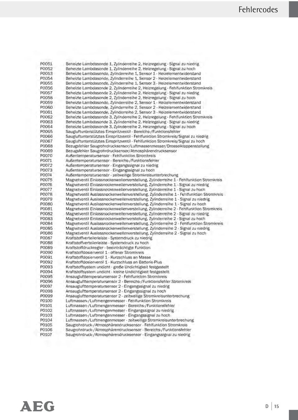
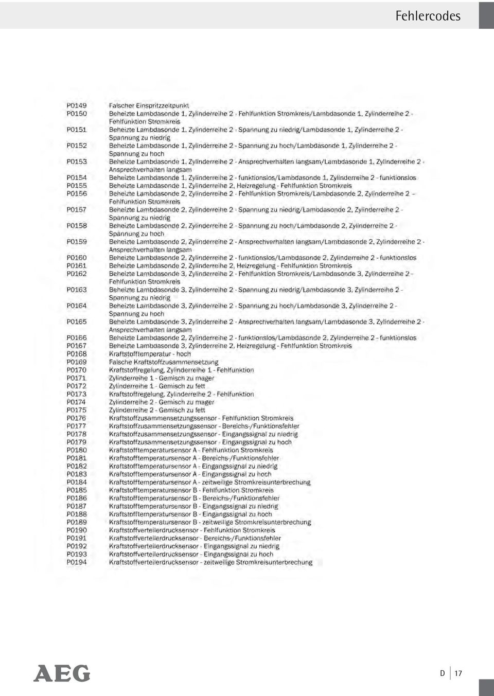
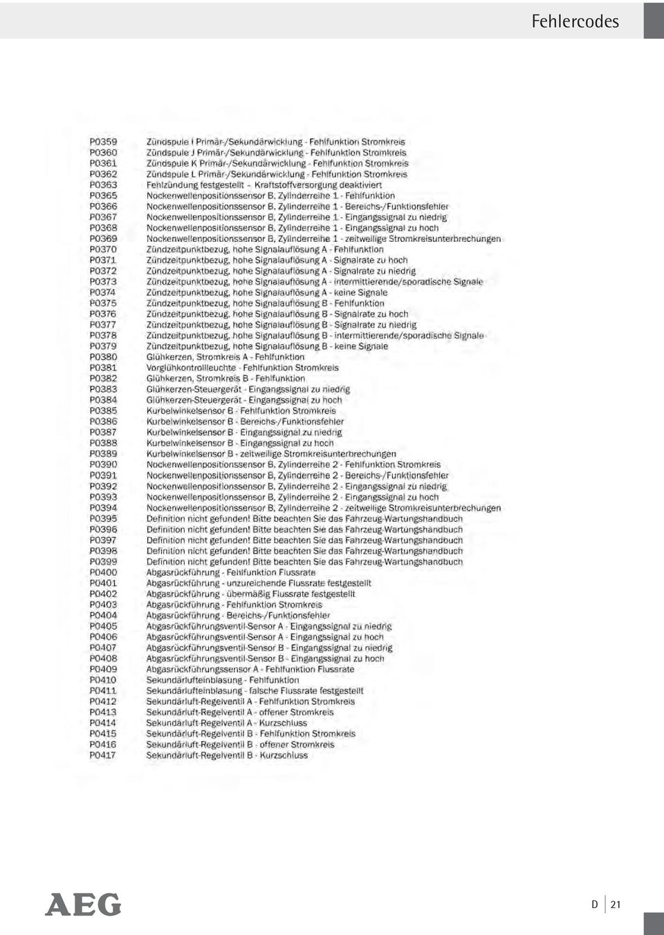
12 Service / Garantie / Konformität / Fehlercode-Verzeichnis Service WARNUNG! Lassen Sie das Gerät nur von qualifiziertem Fachpersonal reparieren. Damit wird die Sicherheit des Gerätes sichergestellt und bleibt erhalten. WARNUNG! Lassen Sie den Austausch des Steckers oder der Anschlussleitung immer von qualifiziertem Fachpersonal ausführen. Damit wird die Sicherheit des Gerätes sichergestellt und bleibt erhalten. Garantie Die allgemeinen Garantiebedingungen beziehen sich auf Produktions- und Materialdefekte. Falls das Gerät fehlerhaft ist, bringen Sie es zu Ihrem Fachhändler bzw. der betreffenden Verkaufsstelle zurück. Um die Garantie- und Reparaturarbeiten am Gerät zu beschleunigen, brauchen Sie Folgendes: - Eine Kopie des Kassenzettels (Lieferschein, Kassenbon) mit dem Erwerbsdatum. - Grund für die Beschwerde oder Beschreibung des Fehlers. Entsorgung Die Verpackung besteht aus umweltfreundlichen Materialien, die Sie über die örtlichen Recyclingstellen entsorgen können. Werfen Sie Elektrogeräte nicht in den Hausmüll! Über Entsorgungsmöglichkeiten für ausgediente Elektrogeräte informieren Sie sich bitte bei Ihrer Gemeinde- oder Stadtverwaltung. Konformität Das Gerät ist konform gemäß folgenden EG-Richtlinien und harmonisierten Normen: - Elektromagnetische Kompatibilität 2004 / 108 / EG, 2004 / 104 / EG ECE R 10 - RoHS-Richtlinie 2002 / 95 / EG Fehlercode-Verzeichnis Fehlercode Seite P P P P P P P P P P P P P P P P P P P P P P P P P P P P P P P P P P P P P P Gemäß Europäischer Richtlinie 2002 / 96 / EC über Elektro- und Elektronik-Altgeräte und Umsetzung in nationales Recht müssen verbrauchte Elektrogeräte getrennt gesammelt und einer umweltgerechten Wiederverwertung zugeführt werden. D 13

13 Fehlercodes 14 D

14 Fehlercodes D 15
15 Fehlercodes 16 D

16 Fehlercodes D 17
17 Fehlercodes 18 D
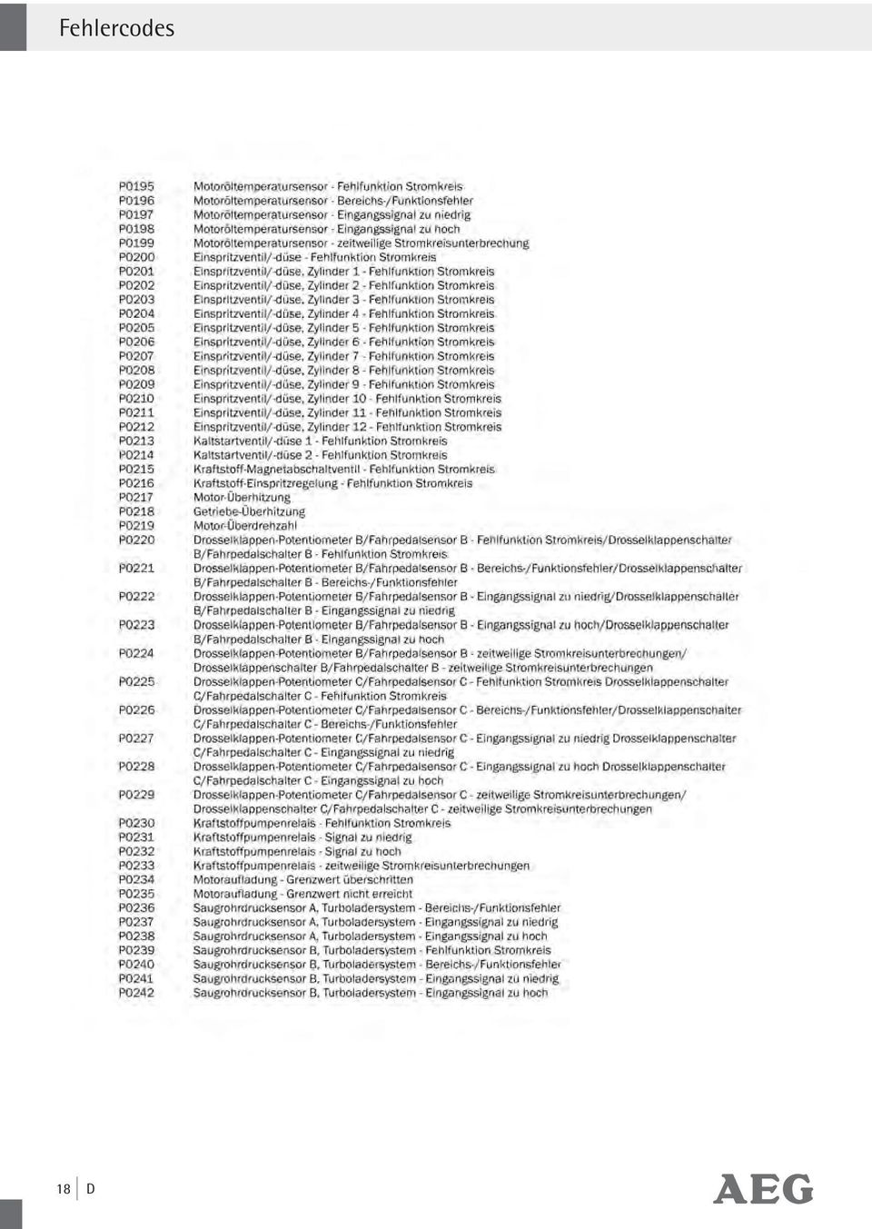
18 Fehlercodes D 19

19 Fehlercodes 20 D

20 Fehlercodes D 21
21 Fehlercodes 22 D
22 Fehlercodes D 23
23 Fehlercodes 24 D
24 Fehlercodes D 25
25 Fehlercodes 26 D
26 Fehlercodes D 27
27 Fehlercodes 28 D
28 Fehlercodes D 29
29 Fehlercodes 30 D
30 Fehlercodes D 31
31 Fehlercodes Abbildungen können geringfügig vom Produkt abweichen. Änderungen, die dem technischen Fortschritt dienen, vorbehalten. Dekoration nicht enthalten. 32 D
32 Table of Contents Introduction Intended use... Page 34 Important product information... Page 34 Scope of delivery... Page 34 Parts description... Page 35 Technical Data... Page 35 Security General safety guidelines... Page 35 Start-up / Operation Analyse error codes... Page 36 Read out error codes... Page 37 Start error diagnosis... Page 37 Call up menu functions... Page 38 Delete diagnosed error codes... Page 38 Menu function inspection program / exhaust system... Page 38 Menu function read Vehicle Identification Number (VIN)... Page 39 Menu function rescanning... Page 39 Vehicle-diagnosed fault (DTC Diagnosed Fault Code), install CD... Page 40 Maintenance and care... Page 40 Service... Page 40 Warranty... Page 40 Disposal... Page 40 Conformity... Page 41 Error code-list... Page 41 Error codes... Page 42 GB 33
33 Introduction In this operating manual / this device the following pictogram s are used: Read operating manual! Observe warning- and safety guidelines! Danger to life and danger of accident for children! Dispose the packaging environmentally friendly! OBD II Diagnostic Device OL 8000 Introduction Make yourself familiar with all functions before first start-up of the equipment and gain inform you about correct handling the device. Read for this the following operating manual carefully. Store this manual carefully. Pass on all documents also when passing on the device to third parties. Intended use The OBD II diagnostic device is to be used for the reading and deletion of vehicle error codes in the on-board computer. This OBD II diagnostic device OL 8000 is suitable for petrol vehicles produced from year 2000 upwards and diesel vehicles from starting from 2003 upwards with a corresponding OBD II connector socket. It is exclusively certified for the private use. All other use or change to the device is considered as not intended and bears substantial dangers. The manufacturer does not take over any liability for damages arising from unintended use. Important product information The designation OBD II stands for»on-board diagnostic system«of the second generation and is used for the check of the data memory in vehicles. The OBD II-system was developed to check emissions-systems and important electronic- and engine components. When the malfunction indicator light Malfunction Indicator Light (MIL) lights up, the error code can be read using the OBD II-Device. These diagnosed codes/malfunction messages (DTC = Diagnosed Trouble Codes) are displayed on the AEG OBD II diagnostic device. These error codes are transmitted from the vehicle data memory to the OBD II -device. The different diagnosed codes identify a certain error on the vehicle. The diagnosed code / malfunction message consists of a 5 digit alphanumeric code. The first digit of the error code is a letter, which identifies the component of the vehicle. The remaining 4 digits will show a number, for example P0202. These error codes help you to identify the main failure causes by means of the operator manual or the supplied software-cd. You will find additional information on the error code in the chapter Vehicle diagnosed error or in the Internet under OBD 2. Scope of delivery After unpacking immediately check the scope of delivery. Examine the device and all parts for damages. Do not take a defective device or part into operation. 1 OBD II Diagnostic Device OL CD with 8000 error codes 34 GB
34 Introduction / Security 1 Storage bag 1 Operating manual Parts description 1 LC-Display 2 Button LÖSCHEN / ERASE 3 Button LESEN / READ 4 Connection cable with OBD II-plug Technical Data Article-No.: Operating Voltage: 12 V via OBD II socket Storage Temperature: 20 to 70 C (04 to 158 F) Operating Temperature: 0 to 50 C (-32 to 122 F) Display: LC-Display with backlight illumination Weight: approx. 250 g, incl. cable Dimensions: approx. 13,8 x 9,0 x 2,5 cm (W x H x D) Security General safety guidelines WARNING! Read all safety guidelines and instructions. Omissions regarding the compliance to safety guidelines and instructions can cause electrical shock, fire and/or serious injuries. Keep all safety guidelines and instructions for future reference. DANGER OF ACCIDENT AND LIFE FOR INFANTS AND CHILDREN! Never leave children unsupervised with the packing material. There is danger of suffocation. This device is not intended for use by persons (including children) with reduced physical, sensory or mental abilities or lack of experience and/or lack of knowledge unless they are supervised by a person responsible for their security or received instructions from this person, how the equipment is to be used. Children should be supervised, in order to guarantee that they do not play with the device. Liquid of any kind shall never penetrate the device. Mortal danger exists by electrical shock otherwise and danger of the damage. Do not let the device get into the hands of children and store it inaccessible for children. Small parts could be swallowed by children and lead to death by suffocation. Children could hurt themselves when using this device. Keep the device away from children. Children do not understand or recognise the possible dangers in handling electrical devices. ATTENTION! DANGER TO LIFE AND DAN- GER OF INJURY, DANGER OF DAMAGE. Secure the vehicle to prevent rolling before checking it with the OBD II Diagnostic Device OL Always engage the hand-/ parking brake and take care that it is not in gear during the check. An automatic gear box must be set to the Park-Position (P) and the hand-/ parking brake must be engaged. Take care that the device is always stored in a secure place. Do not expose the device to oils, grease, dampness, rain or wet ambient conditions. Avoid that water or other liquids run over the device or drip on it. Penetrating water causes an electrical short circuit and can damage the device or the vehicle. Take care, that the device and the plugs are free of dampness. Never connect the device to the vehicle when hands are wet. Do not expose the device to direct sun light. Route the connecting cable in such a way, that no one trips up and the cable gets damaged. GB 35
35 Security / Start-up / Operation Do not use the cables to carry the device or pull it. Always disconnect the device by pulling the plug, do not pull the cable. Operate the device only when it is not damaged. Do not operate the device when it was dropped or damaged otherwise. The device shall not be dismantled, repaired independently or modified (changed). All repairs on the device have to be carried out through a qualified electrician. There are no exchangeable parts inside the device. Before you finally delete errors from the error memory of the OBD II diagnostic device OL 8000, all errors on the vehicles should be fixed. Take care for a safe position when resting the device. Route the connection cable in such a way that it does not disturb the check of the vehicle. Do not lead the cable along sharp edges or corners and hot surfaces. The OBD II diagnostic device OL 8000 is not suitable for the permanent installation in a vehicle. Do not operate the device while driving. Do not connect other cables to the device. Carry out the check with the OBD II diagnostic device OL 8000 only in a safe environment. Keep away clothing, hair, limbs and the OBD II diagnostic device OL 8000 away from moveable or hot engine parts. During the usage of the OBD II diagnostic device OL 8000 the working area must be well ventilated. Comply with safety regulations when the vehicle is jacked or is positioned on a lifting platform or similar. Do not use other measuring devices on the vehicle during the use of the OBD II diagnostic device OL Attention, high voltage in the area of the ignition coils, distributor cap, ignition cable, spark plugs and electrical components in the vehicles. Check if the vehicle is suitable for diagnosis. Connect the OBD II diagnostic device OL 8000 with the vehicle only when the ignition is turned off. The deletion of error codes does not rectify the error on the vehicle. These error codes can be displayed again, until the damage is repaired by a garage. Let a specialised garage repair the malfunction on the vehicle. Start-up / Operation Analyse error codes The enclosed software CD covers most of the error codes displayed. You will receive information on more recent and some special error codes (mainly B, C and U ) either via internet search engines (Search: OBD 2 ) or from your specialised dealer 36 GB
36 Start-up / Operation DTC Example P System Sub-System B = Body C = Chassis P = Propulsion system U = Network Code type 0 = General 1 = Manufacturerspecific 1 = Fuel / Air / lambda sensor 2 = Air inlet- and pressure system 3 = Ignition, misfire control 4 = Emissions- and exhaust control 5 = Speed and brake control system 6 = Engine management / Board computer 7 = Gear box / Hydraulic sensors 8 = Gear box / Hydraulic pressure 9 = Automatic gear The error code shows which component is damaged. Check whether the vehicle has a 16-pole OBD II socket. Check the vehicle emission control label (VECI Label) to see if your vehicle can be diagnosed. The OBD II socket is located in the area of the fuse box below the dashboard in most vehicles. Should you not find the OBD II socket, please see the vehicle manual or ask your vehicle manufacturer. The AEG OBD II diagnostic device OL 8000 works with all vehicles and small vans built as from 2000 with petrol engines and 2003 with diesel engines, which are equipped with OBD II-socket and contain the following diagnostic protocols: VPW, CAN, PWM, KWP2000, ISO 9141 and EKWP2000. The AEG OBD II diagnostic device OL 8000 reads and deletes general and manufacturer specific diagnosed error codes (DTC s) out of the engine control device Vehicles built as from 2002 which are supported with the mode 9, the VIN (Vehicle Identification Number) of the vehicle is read out. With this device, the status of the malfunction warning light (MIL) can be deleted. In addition the emission-display status can be monitored. For this device a separate power supply is not required. The power supply and data transfer follows via the connection cable in combination with the on-board computer of the vehicle. Read out error codes IMPORTANT NOTE! Switch of the vehicle before error diagnosis. The OBD II device must not be connected while the engine is still running or the ignition is still switched on. Start error diagnosis 1. Switch off the ignition of the vehicle 2. Connect the OBD II connection plug 4 with the OBD II connection socket of the vehicle. 3. Wait a short moment until the device is ready for operation and»autoscan 8400«is displayed in the LC-Display Now switch on the ignition but do not start the engine! If the LC-display 1 shows an»error«message, switch of the ignition of the vehicle and wait for approx. 20 seconds GB 37
37 Start-up / Operation Switch on the ignition again without starting the engine. In some vehicle types this»error«message is not shown on the LC-display Now press the button LESEN / READ 3, to read out the OBD II-error memory from the vehicle. The LC-display 1 will show a series of possible diagnostic protocols (PWM, VPW, KWP2000, ISO9141, EKWP2000, CAN). 6. Wait until the device is in the main menu-»menu«will be displayed in the upper line of the LC-display 1. Select»1.DTC«and press the button LESEN / READ If no error code was detected by the device,»dtc: 00«or»NO CODES«is shown on the LC-display If several errors were read out, the LC-display 1 shows the total number of the error codes (for example»fault: 02«). Appended error codes appear on the LC-display with the display»pend:..«. In order to call up the single error codes, press the button LÖSCHEN / ERASE 2 for every single error. After all errors are called up, the error listing starts again from the beginning. 9. If an error code is shown with an attached error code,»pd«is displayed additionally on the LC-display 1. The breakdown of the single error codes can be taken from this operating manual or the attached CD in the chapter Error code list Call up menu functions The AEG OBD II diagnostic device OL 8000 has 5 different menu-functions. Press the button Taste LÖSCHEN / ERASE 2, to call up the separate menus in sequence; 1. DTC: Display of diagnosed error codes 2. ERASE: Deletion of diagnosed error codes 3. I / M: Inspection program for the exhaust system (Readiness Function) 4. VIN: Vehicle Identification Number 5. RESCAN: Rescanning Delete diagnosed error codes 1. Select the menu function»menu 2.ERASE«to delete error codes. Then press the button LESEN / READ 3. The input request will appear in the LC-display 1 whether the error codes shall be deleted»erase? YES NO«. 2. Press the button LÖSCHEN / ERASE 2 to delete the error codes. In case you do not want to delete the error codes, press the button LESEN / READ 3, the menu will be closed. 3. If existing error codes are deleted successfully, it will be confirmed in the LC-display by displaying»erase? DONE!«. 4. If the error codes fail to be deleted»erase? FAIL!«will be shown in the LC-display 1 (= Deletion not carried out). Now press the button LÖSCHEN / ERASE 2, to enter the main menu. A fast and direct deletion of all diagnosed error codes can also be carried out, without selection of the menu function. To do this, press the button LÖSCHEN / ERASE 2 for at least 3 seconds and press the button LESEN / READ 3 afterwards. Menu function inspection program / exhaust system The I / M Readiness function is an inspection program for checking the exhaust system of vehicles suitable for OBD II. ATTENTION! Operate the OBD II diagnostic device OL 8000 only at standstill of the vehicle. 1. Switch on the ignition and start the engine. 2. Select the menu»menu 3.IM«by pressing the button LÖSCHEN / ERASE Now press the button LESEN / READ 3 to call up the status, to detect if the warning light (MIL) is ON or OFF and to start the following control points; Note: Press the button LESEN / READ 3, to go back to the main menu. 38 GB
38 Start-up / Operation MISFIRE Misfire Monitoring Monitoring of misfire and ignition failures FUEL Fuel System Monitoring Monitoring of the fuel-air-ratio CCM Comprehensive Component Monitoring Monitoring of the exhaust relevant components in the vehicle CAT Catalyst Monitoring Monitoring of the catalytic converter HCM Heated Catalyst Monitoring Monitoring of the heated catalyst EVAP Evaporative System Monitoring Monitoring of the evaporative -emissions-system 2AIR Secondary Air Monitoring Monitoring of the secondary air system A / C A / C System Monitoring Monitoring of the air-conditioning system O2S O2 Sensor Monitoring Monitoring of the lambda sensor HO2S O2 Sensor Heater Monitoring Monitoring of the pre- and post connected (HO2S) lambda sensors EGR EGR System Monitoring Monitoring of the exhaust gas recirculation system After completion of the control program, the probable error codes are displayed. The following errors or additional information can occur with the program»3.im«: YES All control programs, which the vehicle supports, have passed the separate diagnosis tests and the warning light MIL is off. NO Not all control programs (at least 1) have completed the diagnosis test READY and / or the warning light is on. Shows that a specific control program has carried out the respective diagnosis test. NOT RDY (NOT READY) A specific control program has not carried out the diagnosis test. N / A This control program is not supported by the vehicle. -> (flashing arrow to the right) The following information can be called up in the LC-Display 1. Press the button LÖSCHEN / ERASE 2 to call up the information. <- (flashing arrow to the left). The previous information is available on the LC-Display 1. Press the button LESEN / READ 3 to call up the information. Press the button LESEN / READ 3 to go back to the main menu. Menu function read Vehicle Identification Number (VIN) With the menu function»4.vin«(vehicle Identification Number) the chassis number of the vehicle can be called up. This is possible for vehicles built as from year 2002, which support the mode Select the menu»menu 4.VIN«by pressing the button LÖSCHEN / ERASE 2. If the vehicle does not support this function»not SUPPORT«appears in the LC-display Press the button LÖSCHEN / ERASE 2. You can now read the 17 digit vehicle identification number. Note: A flashing arrow to the right indicates that more digits of the vehicle identification number can be called up. See these by pressing the button LÖSCHEN / ERASE 2. A flashing arrow to the left indicates that more digits of the vehicle identification number can be called up. See these by pressing the button LÖSCHEN / ERASE 2. Press the button LESEN / READ 3, to go back to the main menu. Menu function rescanning With the menu function»5.rescan«the main data stored in the control unit can be retrieved. GB 39
39 Start-up / Operation / Maintenance and care / Service / Warranty / Disposal Furthermore, this menu function allows a new connection to the vehicle to be made. Select the menu»menu 5.RESCAN«by pressing the button LÖSCHEN / ERASE 2 Then press the button LESEN / READ 3. Press the button LÖSCHEN / ERASE 2, to go back to the main menu. Clean the device and the connection cable 4 regularly with a dry cloth. Never use solvents or other aggressive agents. Do not use any fluids to clean the device. Do not use hard brushes or metallic objects. If really dirty, clean the device with a slightly damp cloth. Always completely dry the device after cleaning Vehicle-diagnosed fault (DTC Diagnosed Fault Code), install CD The information to the separate error codes can be taken from this operating manual, from the chapter error code list. The most important 1000 error codes are listed there. The enclosed software-cd covers most of the error codes. You will receive information on more recent and some special error codes (mainly B, C and U ) either via internet search engines (Search: OBD 2 ) or from your specialised dealer. Install the software on your PC or laptop. Follow the installation instructions of the software. System requirements: Windows 98, Processor min. 133 MHz Windows ME, Processor min. 150 MHz Windows 2000, Processor min. 133 MHz Windows XP, Processor min. 300 MHz Windows Vista, Processor min. 1 GHz Windows 7 ATTENTION! The software on the enclosed CD is only compatible with the above mentioned operating systems. Maintenance and care The device is maintenance free. WARNING! Before cleaning always separate the device from the power supply of the vehicle. To do this, pull out the OBD II connection plug 4. Service WARNING! Leave the repair of the device to qualified technical personnel to repair. Thus the safety of the device is guaranteed and maintained. WARNING! Leave the exchange of the plug or the connecting cable always to qualified technical personnel. Thus the security of the equipment is guaranteed and maintained. Warranty The general guarantee conditions refer to production and material defects. If the device is faulty, bring it to your specialist dealer respectively back to the sales office. In order to accelerate the warranty and repair work on the device, you need the following: - A copy of the receipt (delivery note, bill) with the acquisition date. - Reason for the complaint or description of the error. Disposal The packing consists of pollution free materials, which can dispose of you over the local recycling stations. Do not throw electrical appliances into the domestic waste! 40 GB
40 Disposal / Conformity / Error code-list In accordance with European guideline 2002 / 96 / EC for electrical and old electronic devices and conversion to national law, used electrical appliances must be collected separately and brought to a environmental fair recycling. For disposal possibilities for retired electrical appliances please inform yourself at your community or city administration. Conformity The device conforms to the following EU guidelines and harmonised standards: - Electromagnetic compatibility 2004 / 108 / EG, 2004 / 104 / EG ECE R 10 - RoHS-Guideline 2002 / 95 / EG Error code-list Error code Page P P P P P P P P P P P P P P P P P P P P P P P P P P P P P P P P P P P P GB 41
41 Error codes 42 GB
42 Error codes GB 43
43 Error codes 44 GB
44 Error codes GB 45
45 Error codes 46 GB
46 Error codes GB 47
47 Error codes 48 GB
48 Error codes GB 49
49 Error codes 50 GB
50 Error codes GB 51
51 Error codes 52 GB
52 Error codes GB 53
53 Error codes 54 GB
54 Error codes GB 55
55 Error codes 56 GB
56 Error codes GB 57
57 Error codes 58 GB
58 Error codes Illustrations may vary slightly from the product itself. We reserve the right to administer changes due to technical progress. Decoration not included. GB 59
59 60
60 Table des matières Introduction Utilisation selon les prescriptions... Page 62 Informations importantes sur le produit... Page 62 Volume de livraison... Page 62 Description des pièces... Page 63 Fiche technique... Page 63 Sécurité Instructions générales de sécurité... Page 63 Mise en service / Opération Analyser les codes d erreur... Page 64 Lire le code d erreur... Page 65 Démarrer diagnostic d erreur... Page 65 Consulter les fonctions du menu... Page 66 Effacer codes d erreur de diagnostic...page 66 Fonction de menu de programme d inspection / système d échappement... Page 67 Fonction du menu lire numéro d identification du véhicule (NIV)... Page 68 Fonction du menu de rebalayage avec le scanner... Page 68 Erreur de diagnostic de véhicules (DTC Diagnostic Fault Code), installer CD... Page 68 Entretien et soins L appareil ne nécessite aucun entretien.... Page 68 Service... Page 69 Garantie... Page 69 Élimination... Page 69 Conformité... Page 69 Répertoire des codes d erreur... Page 69 Codes d erreur... Page 70 FR 61
61 Introduction Dans ce manuel d utilisation / dans l appareil on utilise les pictogrammes suivants : OBD II Appareil de diagnostic OL 8000 Introduction Lire le manuel d utilisation! Respectez les instructions d alerte et de sécurité! Familiarisez-vous avec toutes les fonctions de l appareil avant la première mise en marche et renseignez-vous sur la manipulation correcte de l appareil. Lisez pour cela soigneusement le guide d utilisation suivant. Gardez ce manuel dans un lieu sûr. Remettez tous les documents lors du transfert de l appareil à un nouveau propriétaire. Utilisation selon les prescriptions L appareil de diagnostic OL 8000 d OBD est prévu pour la lecture et l effacement des codes d erreur dans l ordinateur de bord du véhicule. Cet appareil de diagnostic OL 8000 d OBD est adapté pour les véhicules à essence construits à partir de l année 2000 et les véhicules diesel construits à partir de l année 2003 avec des prises femelles OBD II adaptées. Il est homologué uniquement pour l utilisation dans le domaine privé. Toute utilisation ou modification de l appareil doit être considérée comme non conforme et entraînerait de graves dangers. Pour les dommages qui ont surgi en raison d une utilisation non conforme, le fabricant n assumera aucune responsabilité. Informations importantes sur le produit Le terme OBD II est synonyme de «système de diagnostic de bord» de la deuxième génération Danger de mort de d accident pour les tous petits et les enfants! Éliminez l emballage et l appareil de manière respectueuse de l environnement! et est utilisé pour l examen de la mémoire de stockage de données dans des véhicules. Le système OBD II a été développé pour l examen des systèmes d émission et les principaux composants électroniques et mécaniques du moteur. Si le voyant d avertissement de dysfonctionnement Malfunction Indicator Light (MIL) brille, on pourra lire le code d erreur à l aide de l appareil OBD II. Sur l appareil de diagnostic d AEG OL 8000 OBD sont affichés ces codes de diagnostic/messages d erreur (DTC = Diagnostic Trouble Codes). Ces messages d erreur sont transmis par la mémoire du véhicule à l appareil OBD II. Les différents codes de diagnostic identifient une défaillance particulière du véhicule. Le code de diagnostic / message d erreur est composé d un code alphanumérique à 5 caractères. Dans la première position du message d erreur il y a une lettre qui définit le groupe constructif du véhicule concerné. Les 4 autres positions montrent un chiffre, par exemple P0202. Ces messages d erreur peuvent vous aider à identifier la plupart des causes en utilisant le manuel d utilisation ou le CD fourni contenant le logiciel. Pour plus d informations sur le code d erreur, consulter le chapitre «Codes de diagnostic du véhicule» ou par Internet avec le mot-clé de recherche OBD Volume de livraison Contrôlez immédiatement après le déballage le volume de livraison. Vérifiez si l appareil et ses 62 FR
62 Introduction / Sécurité composants présentent des dommages. Ne réalisez pas la mise en marche d un appareil défectueux ou avec des parties défectueuses. 1 appareil de diagnostic OL 8000 d OBD II 1 CD avec 8000 codes d erreur 1 sacoche de rangement 1 manuel d utilisation Description des pièces 1 Écran LC 2 Touche «EFFACER / ERASE» 3 Touche «LIRE / READ» 4 Câble de connexion avec connecteur OBD II Fiche technique No. article : Tension de fonctionnement: 12 V avec prise femelle OBD II Température de stockage: 20 à 70 C (04 à 158 F) Température de fonctionnement: 0 à 50 C (-32 à 122 F) Affichage : Écran LC avec rétroéclairage Poids : env. 250 g, y compris le câble Dimensions : env. 13,8 x 9,0 x 2,5 cm (L x H x P) Sécurité Instructions générales de sécurité AVERTISSEMENT Lisez toutes les indications de sécurité et instructions. Les manquements dans le respect des indications de sécurité et instructions peuvent provoquer un choc électrique, des brulures et/ou des blessures graves. Conservez toutes les indications de sécurité et instructions pour une utilisation future. DANGER DE MORT DE D ACCI- DENT POUR LES TOUS PETITS ET LES ENFANTS! Ne laissez jamais les enfants sans surveillance avec le matériel d emballage. Il y a danger d asphyxie. Cet appareil n est pas destiné à être utilisé par des personnes (incluant des enfants) avec des capacités physiques, sensorielles ou psychiques limitées ou avec un manque d expérience et/ou un manque de savoir-faire, à moins qu elles soient surveillées par une personne responsable de leur sécurité ou qu elles reçoivent des instructions sur comment utiliser cet appareil. Les enfants devront être surveillés, afin de vérifier qu ils ne jouent pas avec l appareil. Aucun liquide, de n importe quelle nature, ne devra pénétrer dans l appareil. En cas contraire il y aura danger de mort par choc électrique et danger de dommages matériels. Ne laissez pas l appareil accessible aux enfants et gardez-le hors de leur portée. Les petites pièces peuvent être avalées par les enfants et provoquer leur mort par asphyxie. Les enfants peuvent se blesser lors de l utilisation de l appareil. Tenir les enfants à l écart de l appareil. Les enfants ne comprennent ou ne reconnaissent pas les dangers potentiels associés à l utilisation d appareils électriques. ATTENTION! DANGER DE MORT ET DE BLESSURES ET RISQUE DE DOMMAGES MATÉRIELS. Immobilisez le véhicule avant un examen avec l appareil de diagnostic OL 8000 d OBD II, de sorte qu il ne puisse pas se déplacer. Tirez toujours du frein à main/frein de stationnement et assurez-vous que lors de l examen aucune vitesse ne soit engagée. Avec une transmission automatique, on devra ajuster la «position de stationnement» (P) et tirer du frein à main / frein de stationnement. Assurez-vous que l équipement soit gardé toujours dans un endroit sûr. N exposez pas l appareil à des d huiles, de graisses, à l hu- FR 63
BEDIENUNGS- UND SICHERHEITSHINWEISE 3 OPERATION AND SAFETY NOTES 19 UNITÀ PRINCIPALE LP PLUS INDICAZIONI PER L USO E PER LA SICUREZZA 47
 DE LADEGERÄT LP PLUS BEDIENUNGS- UND SICHERHEITSHINWEISE 3 GB MAIN UNIT LP PLUS OPERATION AND SAFETY NOTES 19 FR UNITÉ PRINCIPALE LP PLUS INSTRUCTIONS D UTILISATION ET CONSIGNES DE SÉCURITÉ 33 IT UNITÀ
GUIDELINES FOR CONNECTION TO FTP SERVER TO TRANSFER PRINTING DATA
 GUIDELINES FOR CONNECTION TO FTP SERVER TO TRANSFER PRINTING DATA What is an FTP client and how to use it? FTP (File transport protocol) - A protocol used to transfer your printing data files to the MAFRAPRINT
USER'S MANUAL FAN MOTOR DRIVER FMD-02
 USER'S MANUAL FAN MOTOR DRIVER FMD-02 IMPORTANT NOTE: Read this manual carefully before installing or operating your new air conditioning unit. Make sure to save this manual for future reference. FMD Module
Personenwaage Osobní váha MD 13894. Bedienungsanleitung Návod k obsluze
 Personenwaage Osobní váha MD 13894 Bedienungsanleitung Návod k obsluze Inhalt Zu dieser Anleitung... 2 In dieser Anleitung verwendete Symbole und Signalwörter...2 Einsatzbereich/bestimmungsgemäßer Gebrauch...3
2N Voice Alarm Station
 2N Voice Alarm Station 2N Lift1 Installation Manual Version 1.0.0 www.2n.cz EN Voice Alarm Station Description The 2N Voice Alarm Station extends the 2N Lift1/ 2N SingleTalk with an audio unit installed
POLO 2.0. Art. Nr.: 5460 - BEZPEČNOST - OBSLUHA. Výhradní dovozce a distributor pro Českou republiku a Slovensko Caravan Centrum Hykro s.r.o.
 POLO 2.0 TERRASSENHEIZUNG PLYNOVÝ ZÁŘIČ GAS Výhradní dovozce a distributor pro Českou republiku a Slovensko Caravan Centrum Hykro s.r.o. Ořešská Enders Colsman 1542 AG 155 00 Praha 5 - Řeporyje tel.: +420
Litosil - application
 Litosil - application The series of Litosil is primarily determined for cut polished floors. The cut polished floors are supplied by some specialized firms which are fitted with the appropriate technical
Easy-6 Pivottür mit Seitenwand / Otočné dveře s boční stěnou
 Easy-6 Pivottür mit Seitenwand / Otočné dveře s boční stěnou Lesen Sie die Bedienungsanleitung sorgfältig durch und bewahren Sie diese für den späteren Gebrauch auf. Wir empfehlen die Montage unseres Produktes
User manual SŘHV Online WEB interface for CUSTOMERS June 2017 version 14 VÍTKOVICE STEEL, a.s. vitkovicesteel.com
 1/ 11 User manual SŘHV Online WEB interface for CUSTOMERS June 2017 version 14 2/ 11 Contents 1. MINIMUM SYSTEM REQUIREMENTS... 3 2. SŘHV ON-LINE WEB INTERFACE... 4 3. LOGGING INTO SŘHV... 4 4. CONTRACT
Herzlichen Glückwunsch! Sie haben sich für ein Qualitätsprodukt der Firma Zangenberg entschieden.
 Herzlichen Glückwunsch! Sie haben sich für ein Qualitätsprodukt der Firma Zangenberg entschieden. Bitte lesen Sie die Anleitung vor der ersten Benutzung aufmerksam durch. Sie erhalten wichtige Hinweise
UŽIVATELSKÁ PŘÍRUČKA
 UŽIVATELSKÁ PŘÍRUČKA Plni víry a naděje míříme kupředu. S odhodláním zlepšujeme své dovednosti. Zapomeňte na zklamání, ale nikoli na svůj nevyužitý potenciál. Touha překonat sám sebe a dosáhnout hranice
Training Board TB series 3. SolderBoard
 Training Board TB series 3 SolderBoard Elektronická stavebnice SOLDERBOARD byla speciálně navržena pro účely praktické výuky ručního osazování a pájení desek plošných spojů v technologii SMT. Je levným
Mechanika Teplice, výrobní družstvo, závod Děčín TACHOGRAFY. Číslo Servisní Informace Mechanika: 5-2013
 Mechanika Teplice, výrobní družstvo, závod Děčín TACHOGRAFY Servisní Informace Datum vydání: 20.2.2013 Určeno pro : AMS, registrované subj.pro montáž st.měř. Na základě SI VDO č./datum: Není Mechanika
WL-5480USB. Quick Setup Guide
 Quick Setup Guide 1 Czech 7 Install Utility Software Note1: Before installing the utility software, DO NOT inserts the into your computer. If the adapter is inserted already, Windows will detect the adapter
UPM3 Hybrid Návod na ovládání Čerpadlo UPM3 Hybrid 2-5 Instruction Manual UPM3 Hybrid Circulation Pump 6-9
 www.regulus.cz UPM3 Hybrid Návod na ovládání Čerpadlo UPM3 Hybrid 2-5 Instruction Manual UPM3 Hybrid Circulation Pump 6-9 CZ EN UPM3 Hybrid 1. Úvod V továrním nastavení čerpadla UPM3 Hybrid je profil PWM
Uživatelská příručka. USB Charger UCH20
 Uživatelská příručka USB Charger UCH20 Obsah Úvod...3 USB Charger popis... 3 Používání nabíječky USB... 4 Nabíjení zařízení... 4 Právní informace... 5 Declaration of Conformity...6 2 Úvod USB Charger popis
Qualität aus erster Hand! Sie haben sich für ein Markenprodukt der Firma Zangenberg entschieden.
 Qualität aus erster Hand! Sie haben sich für ein Markenprodukt der Firma Zangenberg entschieden. Bitte lesen Sie die Anleitung vor der ersten Benutzung aufmerksam durch. Sie erhalten wichtige Hinweise
2N LiftIP. Voice Alarm Station. Communicator for Lifts. Version
 2N LiftIP Communicator for Lifts Voice Alarm Station Version 2.4.0 www.2n.cz Description The 2N Voice Alarm Station is a switch that helps you extend 2N LiftIP with one or more audio units installed on
USER'S MANUAL FAN MOTOR DRIVER FMD-01, FMD-03
 USER'S MANUAL FAN MOTOR DRIVER FMD-01, FMD-03 IMPORTANT NOTE: Read this manual carefully before installing or operating your new air conditioning unit. Make sure to save this manual for future reference.
Tento materiál byl vytvořen v rámci projektu Operačního programu Vzdělávání pro konkurenceschopnost.
 Tento materiál byl vytvořen v rámci projektu Operačního programu Vzdělávání pro konkurenceschopnost. Projekt MŠMT ČR Číslo projektu Název projektu školy Klíčová aktivita III/2 EU PENÍZE ŠKOLÁM CZ.1.07/1.4.00/21.2146
ROLZ-2. Portable AV/Conference Center. Assembly Instructions
 1 ROLZ-2 Portable AV/Conference Center Assembly Instructions Rolz-2 Portable AV/Conference Center Part Drawing Description Qty Part Drawing Description Qty Hardware List A 1 ½ Flat Head Screw 2 EA P-1
STAVEBNÍ PŘIPRAVENOST GILOTINA VLO DIMENSIONAL SHEET VLO MASSBLATT VERTIKALER BESCHLAG VLO МОНТАЖ МЕТАЛЛОКОНСТРУКЦИИ ВОРОТ СИСТЕМЫ ГИЛЬОТИНА ВЛО
 CZ VOLNÝ PROSTOR PRO POHYBUJÍCÍ SE VRATA EN FREE SPACE FOR THE DOORMOVEMENT DE FREIRAUM FÜR DIE BEWEGUNGSABLÄUFE RU РАЗМЕРЫ НЕОБХОДИМЫЕ ДЛЯ УСТАНОВКИ ВОРОТ CZ A - šířka otvoru B - výška otvoru C - nadpraží
Uživatelská příručka. Xperia P TV Dock DK21
 Uživatelská příručka Xperia P TV Dock DK21 Obsah Úvod...3 Přehled zadní strany stanice TV Dock...3 Začínáme...4 Správce LiveWare...4 Upgradování aplikace Správce LiveWare...4 Použití stanice TV Dock...5
DATA SHEET. BC516 PNP Darlington transistor. technický list DISCRETE SEMICONDUCTORS Apr 23. Product specification Supersedes data of 1997 Apr 16
 zákaznická linka: 840 50 60 70 DISCRETE SEMICONDUCTORS DATA SHEET book, halfpage M3D186 Supersedes data of 1997 Apr 16 1999 Apr 23 str 1 Dodavatel: GM electronic, spol. s r.o., Křižíkova 77, 186 00 Praha
EINBAUANWEISUNG FÜR SCHALLDÄMM-SET BWS/DWS MONTÁŽNÍ NÁVOD PRO ZVUKOVĚ IZOLAČNÍ SOUPRAVY BWS/DWS
 EINUNWEISUNG FÜR SCHLLÄMM-SET WS/WS MONTÁŽNÍ NÁVO PRO ZVUKOVĚ IZOLČNÍ SOUPRVY WS/WS Wichtige Hinweise - unbedingt beachten! ůležitá upozornění bezpodmínečně dodržujte! Schalldämm-Set muss vollständig und
Einbauanleitung zu Elektro-Einbausatz 736652 Elektro-Einbausatz für Anhängerkupplung, 7-polig, 12 Volt, nach ISO 1724
 Einbauanleitung zu Elektro-Einbausatz 736652 Elektro-Einbausatz für Anhängerkupplung, 7-polig, 12 Volt, nach ISO 1724 PEUGEOT 307 Kombi ab ab 04/02 PEUGEOT 307 Station Wagon ab 04/02 Inhalt: 1 Steckdosen-Gehäuse
Hi-Res Audio/DNC Headset MDR-NC750
 Uživatelská příručka Hi-Res Audio/DNC Headset MDR-NC750 Obsah Začínáme...3 Úvod...3 Přehled... 3 Základy práce...4 Nošení náhlavní soupravy...4 Připojení náhlavní soupravy k vašemu zařízení... 4 Nastavení
Einbauanleitung zu Elektro-Einbausatz 736694 Elektro-Einbausatz für Anhängerkupplung, 7-polig, 12 Volt, nach ISO 1724
 Einbauanleitung zu Elektro-Einbausatz 736694 Elektro-Einbausatz für Anhängerkupplung, 7-polig, 12 Volt, nach ISO 1724 Peugeot 206 alle Modelle ab 09/98 Inhalt: 1 Steckdose 7-polig mit Abschaltkontakt für
DEMATECH PREISANGEBOT / CENOVÁ NABÍDKA
 PREISANGEBOT / CENOVÁ NABÍDKA Maschinenart / Druh stroje: Anlage zum Pelletieren / Pellet line / Peletovací linka Marke und Typ / Značka a typ: MGL 400 Baujahr / Rok výroby: 2011 Hersteller / Výrobce:
PC/104, PC/104-Plus. 196 ept GmbH I Tel. +49 (0) / I Fax +49 (0) / I I
 / I Fax +49 (0) / I I") E L E C T R O N I C C O N N E C T O R S 196 ept GmbH I Tel. +49 (0) 88 61 / 25 01 0 I Fax +49 (0) 88 61 / 55 07 I E-Mail sales@ept.de I www.ept.de Contents Introduction 198 Overview 199 The Standard 200
E L E C T R O N I C C O N N E C T O R S 196 ept GmbH I Tel. +49 (0) 88 61 / 25 01 0 I Fax +49 (0) 88 61 / 55 07 I E-Mail sales@ept.de I www.ept.de Contents Introduction 198 Overview 199 The Standard 200
Střední průmyslová škola strojnická Olomouc, tř.17. listopadu 49
 Střední průmyslová škola strojnická Olomouc, tř.17. listopadu 49 Výukový materiál zpracovaný v rámci projektu Výuka moderně Registrační číslo projektu: CZ.1.07/1.5.00/34.0205 Šablona: III/2 Anglický jazyk
 [KLICK] GB Instruction Manual POWERLINE 4 LIGHT FOREWORD Dear Customer, Thank you for purchasing the POWERLINE 4 LIGHT charger. These operating instructions will help you to get the best from your charger.
2N LiftIP. IO Extender. Communicator for Lifts. Version
 2N LiftIP Communicator for Lifts IO Extender Version 2.4.0 www.2n.cz Description The IO extender helps you extend 2N LiftIP with 1 input and 2 outputs. The purpose of the input is to cancel the rescue
Introduction to MS Dynamics NAV
 Introduction to MS Dynamics NAV (Item Charges) Ing.J.Skorkovský,CSc. MASARYK UNIVERSITY BRNO, Czech Republic Faculty of economics and business administration Department of corporate economy Item Charges
 11.12. 100 ΕΙΣΟΔΟΣ = E / ENTRANCE = E = = 1174 550 ΤΥΠΟΠΟΙΗΜΕΝΟ ΚΥ = 2000 (ΕΠΙΛΟΓΗ: 2100) / CH STANDARD = 2000 (OPTIONAL: 2100) 243 50 ΚΥ/CH + 293 ΚΥ/CH +103 100 ΚΥ /CH 6 11 6 20 100 0,25 ΚΑ (CO) + 45
FIRE INVESTIGATION. Střední průmyslová škola Hranice. Mgr. Radka Vorlová. 19_Fire investigation CZ.1.07/1.5.00/
 FIRE INVESTIGATION Střední průmyslová škola Hranice Mgr. Radka Vorlová 19_Fire investigation CZ.1.07/1.5.00/34.0608 Výukový materiál Číslo projektu: CZ.1.07/1.5.00/21.34.0608 Šablona: III/2 Inovace a zkvalitnění
Buderus System Logatherm Wps K
 Buderus System Logatherm Wps K XV1100K(C)/XV1100SK(C) All rights reserverd. Any reprinting or unauthorized use wihout the written permission of Buderus System Logatherm Wps K Corporation, is expressly
SERVISNÍ MANUÁL PEGAS 250 E CEL OVO SERVICE MANUAL PEGAS 250 E CEL OVO
 MG136-1 PEGAS 250 E CEL OVO SERVICE MANUAL page 1 SERVISNÍ MANUÁL PEGAS 250 E CEL OVO SERVICE MANUAL PEGAS 250 E CEL OVO 1. VAROVÁNÍ WARNING UPOZORNĚNÍ Pouze osoba splňující kvalifikaci danou zákonem je
Připojení internetového modulu econet300 Do regulátoru ecomax 810P3-L TOUCH.
 Připojení internetového modulu econet300 Do regulátoru ecomax 810P3-L TOUCH. Connection of econet300 internet module to ecomax 810P3-L TOUCH Controller. Prosím ověřte verzi softwaru vašeho modulu ecomax.
Postup objednávky Microsoft Action Pack Subscription
 Postup objednávky Microsoft Action Pack Subscription DŮLEŽITÉ: Pro objednání MAPS musíte být členem Microsoft Partner Programu na úrovni Registered Member. Postup registrace do Partnerského programu naleznete
PLASTICPARTS. -Parts not for use. -Teile werden nicht verwendet. -Pieces a ne pas utiliser. -Tyto díly nepoužívejte při stavbě. -
 742 SpitfireMk.VI 1/72 A> 70120 A PLASTICPARTS B> 70120 B C> 70120 C D> F> E> 70120 D 70120 E GUNZE 70120 F H4 C4 YELLOW H12 H13 C3 FLAT RED H33 C81 RUSSET H51 C11 LIGHT GULL GRAY H71 C21 MIDDLE STONE
WICHTIG - FÜR SPÄTERE VERWENDUNG AUFBEWAHREN - SORGFÄLTIG LESEN.
 WICHTIG - FÜR SPÄTERE VERWENDUNG AUFBEWAHREN - SORGFÄLTIG LESEN. Ignorierung der Warnungen und Hinweise in der Gebrauchsanleitung können zu ernsten Verletzungen und Todesfällen führen. Achtung: Zur Vermeidung
TCNF 185 TCNF 185 IX NO-FROST FRIGORÍFICO
 TCNF 185 TCNF 185 IX NO-FROST FRIGORÍFICO ATTENTION Cet appareil est destiné à un usage domestique uniquement. Toute utilisation autre que celle prévue pour cet appareil, ou pour une autre application
1-AYKY. Instalační kabely s Al jádrem. Standard TP-KK-133/01, PNE 347659-3. Konstrukce. Použití. Vlastnosti. Installation cables with Al conductor
 Instalační kabely s Al jádrem Installation cables with Al conductor Standard TP-KK-133/01, PNE 347659-3 4 3 2 1 Konstrukce Construction 1 Hliníkové jádro Aluminium conductor 2 Izolace PVC 3 Výplňový obal
Diagnostický přístroj pro automobily Cartrend OBD II Obj. č.: 85 71 26
 Diagnostický přístroj pro automobily Cartrend OBD II Obj. č.: 85 71 26 Obsah Strana 1. Úvod a účel použití testovacího (diagnostického) přístroje...3 2. Několik informací o diagnóze OBD II...4 3. Bezpečnostní
L-force Drives. EDK84DGFCxxxx.O=I. Ä.O=Iä. Montážní návod motec. E84DGFCxxxx. Komunikační modul Communication unit
 EDK8DGFCxxxx.O=I Ä.O=Iä L-force Drives Montážní návod 800 motec E8DGFCxxxx Komunikační modul Communication unit 0 0.7 kw 7.kW E8DG0a E8DG0b EDK8DGFCxxxx CS.0 V Warnings! Operation of this equipment requires
Microsoft Lync WEB meeting
 User - documentation ENU and CZ version Microsoft Lync WEB meeting - Připojení k WEB meetingu prostřednictvím Microsoft Lync Date: 10. 5. 2013 Version: 0.2 ENU, CZ www.axiomprovis.cz Version description:
obal manuálu, asi něco podobného jako u LC 100 asi by to chtělo lepší obrázek!!! FYTOSCOPE FS130 Instruction Guide
 obal manuálu, asi něco podobného jako u LC 100 asi by to chtělo lepší obrázek!!! FYTOSCOPE FS130 Instruction Guide možná tohle trochu zmenšit a dát sem i to varování LED RADIATION co je na další straně
VESTAVBOVÝ RÁM - ROLLO JUMBO
 VESTAVBOVÝ RÁM - ROLLO JUMBO Montageanleitung / Mounting Instruction / Montážní návod Nur von Erwachsenen zu bedienen! Kinder nicht an der Bildwand spielen lassen! Operation by adults only! Do not let
ROEDL & PARTNER ERSTES BÜRO IN PRAG MATERIÁLY PRO UČITELE
 ROEDL & PARTNER ERSTES BÜRO IN PRAG MATERIÁLY PRO UČITELE Roedl & Partner: Erstes Büro in Prag A: So und Sie haben sich vorgestellt, dass Sie hier in Prag ein Büro haben werden, ist das richtig? B: Wir
Gymnázium a Střední odborná škola, Rokycany, Mládežníků 1115
 Číslo projektu: Číslo šablony: Název materiálu: Gymnázium a Střední odborná škola, Rokycany, Mládežníků 1115 CZ.1.07/1.5.00/34.0410 II/2 Parts of a computer IT English Ročník: Identifikace materiálu: Jméno
Vánoční sety Christmas sets
 Energy news 7 Inovace Innovations 1 Vánoční sety Christmas sets Na jaře tohoto roku jste byli informováni o připravované akci pro předvánoční období sety Pentagramu koncentrátů a Pentagramu krémů ve speciálních
SPECIFICATION FOR ALDER LED
 SPECIFICATION FOR ALDER LED MODEL:AS-D75xxyy-C2LZ-H1-E 1 / 13 Absolute Maximum Ratings (Ta = 25 C) Parameter Symbol Absolute maximum Rating Unit Peak Forward Current I FP 500 ma Forward Current(DC) IF
GRAND KANCELÁŘSKÉ STOLY DR2 1800 * 900 DR2 1800 * 900 DR1 1600 * 800 DR1 1600 * 800 DZ 1600 * 900 DZ 1600 * 900 SKLADEBNOST SYSTÉMU GRAND
 KANCELÁŘSKÉ STOLY PRAVÁ SESTAVA F SKLADEBNOST SYSTÉMU GRAND LEVÁ SESTAVA F D D C C PŘÍSEDOVÉ VARIANTY NESENÉ NA VYLOŽENÉ KONZOLE PODNOŽE B E B E A A DR2 1 * DR2 1 * DR1 * DZ * DR1 * DZ * DESKY ZÁKLADNÍ
REFERENCE: MTF4 CODIC:
 MARQUE: PROLINE REFERENCE: MTF4 CODIC: 3523551 MTF4 AVERTISSEMENTS Cet appareil est destiné à un usage domestique uniquement. Toute utilisation autre que celle prévue pour cet appareil, ou pour une autre
Quick Start Guide. Clear. Rychlý průvodce nastavením
 CZ EN Quick Start Guide Clear Rychlý průvodce nastavením Measurement Měření Před Fully prvním charge použitím the blood plně pressure dobijte monitor baterii before přístroje. first use. 1 Rest your bare
VOŠ, SPŠ automobilní a technická. Mgr. Marie Šíchová. At the railway station
 Název SŠ: Autor: Název: Tematická oblast: VOŠ, SPŠ automobilní a technická Mgr. Marie Šíchová At the railway station VOŠ, Provoz a ekonomika dopravy, cizí jazyk, angličtina B, odborné téma Železniční doprava
Mezinárodní závody Zpívající fontány
 Plavecký klub Mariánské Lázně Vás srdečně zve na Mezinárodní závody Zpívající fontány Internationales Jugendwettschwimmen VI. ročník / V. Jahrgang Memoriál Jiřího Urbance Datum konání / Datum: 01.10. 2011
Saurer Regen. V rámci následujícího úkolu se studenti seznámí s odborným textem v němčině. Dozvědí se základní informace o kyselém dešti.
 NĚMČINA Saurer Regen V rámci následujícího úkolu se studenti seznámí s odborným textem v němčině. Dozvědí se základní informace o kyselém dešti. Gymnázium Frýdlant, Mládeže 884, příspěvková organizace
Training Board TB series 3. PracticeBoard
 Training Board TB series 3 PracticeBoard Elektronická stavebnice PRACTICEBOARD byla speciálně navržena pro účely praktické výuky ručního osazování a pájení desek plošných spojů v technologii SMT. Je levným
Stříkací pistole. Striekacia pištoľ 10.25-007
 Stříkací pistole Profi-Farbpistole Striekacia pištoľ 10.25-007 CZ 7 6 2 4 5 3 1 1) rychloupínací konektor 2) regulace množství barvy 3) regulace množství vzduchu 4) nastavení stříkacího modulu 5) spoušť
Ecosun CH. Napětí V. 1096x155x115* 230 V 1N I IP 44 Ecosun CH x155x115*
 Návod k obsluze a montáži N631/R02 (06.08.14 ) Ecosun CH Sálavé panely do kostelních lavic 1. Použití Sálavé panely Ecosun CH jsou určeny k instalaci pod pevně připevněné kostelní lavice. Panely se instaluji
 If there is any inconsistency of weather forecast between Local Weather Station and this unit, the Local Weather Station's forecast should prevail. The trend pointer displayed on the LCD indicates the
WORKSHEET 1: LINEAR EQUATION 1
 WORKSHEET 1: LINEAR EQUATION 1 1. Write down the arithmetical problem according the dictation: 2. Translate the English words, you can use a dictionary: equations to solve solve inverse operation variable
Einbauanleitung zu Elektro-Einbausatz 736566 Elektro-Einbausatz für Anhängerkupplung, 7-polig, 12 Volt, nach ISO 1724. FIAT PUNTO ab 09/99
 Einbauanleitung zu Elektro-Einbausatz 736566 Elektro-Einbausatz für Anhängerkupplung, 7-polig, 12 Volt, nach ISO 1724 FIAT PUNTO ab 09/99 Inhalt: 1 Steckdose 7-polig, 1 Leitungssatz 7-adrig, 1 Gummidichtung
Lenovo A5000. Quick Start Guide v1.0. English/Česky
 Lenovo A5000 Quick Start Guide v1.0 English/Česky English Read this guide carefully before using your smartphone. Learning more Getting support Electronic emission notices To learn more information about
TECHNICKÝ LIST řada mechanických odvaděčů kondenzátu AUTODRAIN TECHNICAL DATA SHEET for mechanical autodrain equipment AUTODRAIN
 Popis: Nádoba s mechanickým plovákem k odstraňování pevných nečistot, vody, aerosolů, uhlovodíků, prachu oddělených separátory KING AIR se systémem stlačeného vzduchu. Rozdělení dle využití instalace:
Mgr. Jakub Lukeš. Praha (pracovní list) Ročník: 1. 4. Datum vytvoření: listopad 2013 VY_32_INOVACE_09.2.16.NEJ
 Ročník: 1. 4. Datum vytvoření: listopad 2013 VY_32_INOVACE_09.2.16.NEJ") Autor: Mgr. Jakub Lukeš Předmět/vzdělávací oblast: Německý jazyk Tematická oblast: Téma: Poznatky o zemích Praha (pracovní list) Ročník: 1. 4. Datum vytvoření: listopad 2013 Název: VY_32_INOVACE_09.2.16.NEJ
Autor: Mgr. Jakub Lukeš Předmět/vzdělávací oblast: Německý jazyk Tematická oblast: Téma: Poznatky o zemích Praha (pracovní list) Ročník: 1. 4. Datum vytvoření: listopad 2013 Název: VY_32_INOVACE_09.2.16.NEJ
ROLLO STANDARD ELECTRIC. Montageanleitung / Mounting Instruction / Montážní návod
 ROLLO STANDARD ELECTRIC Montageanleitung / Mounting Instruction / Montážní návod Teileliste / Parts List / Seznam dílů (1) 2x ( 2) 2x (3) 2x Nur von Erwachsenen zu bedienen! Kinder nicht an der Bildwand
Pokyny k použití. Model-300. Napájecí zdroj. Návod na obsluhu Operating Instructions. se systémem Aquacontrol Napájací zdroj
 Pokyny k použití Model-300 Návod na obsluhu Operating Instructions Napájecí zdroj se systémem Napájací zdroj so systémom Power Supply with System BK 0011900 / PC AQUACONTROL Kryt aquacontrol Kryt aquacontrol
Size / Světlost : DN 1/4 to 4 / DN 1/4 až 4
 Size / Světlost : 1/4 to 4 / 1/4 až 4 Ends / Konce : Threaded BSP / Závitové BSP Min. Temperature / Minimální teplota : -20 C Max. Temperature / Maximální teplota : +180 C Max. Pressure / Maximální tlak
2N Lift8 Audio unit machine room
 2N Lift8 Audio unit machine room Brief Manual Version 3.0.0 www.2n.cz The machine room audio unit is intended for installation in the machine room or as an intercom solution located in the reception.
2. Entity, Architecture, Process
 Evropský sociální fond Praha & EU: Investujeme do vaší budoucnosti Praktika návrhu číslicových obvodů Dr.-Ing. Martin Novotný Katedra číslicového návrhu Fakulta informačních technologií ČVUT v Praze Miloš
Czech Republic. EDUCAnet. Střední odborná škola Pardubice, s.r.o.
 Czech Republic EDUCAnet Střední odborná škola Pardubice, s.r.o. ACCESS TO MODERN TECHNOLOGIES Do modern technologies influence our behavior? Of course in positive and negative way as well Modern technologies
AUTOMATICKÝ DÁVKOVAČ Harvia. Návod na instalaci a použití instructions for installation and Use
 AUTOMATICKÝ DÁVKOVAČ Harvia Návod na instalaci a použití instructions for installation and Use 15122011 CZ EN 1. OBECNÉ INFORMACE 1. GENEraL Účelem Harvia automatického dávkovače je aplikovat vodu a směs
Název společnosti: VPK, s.r.o. Vypracováno kým: Ing. Michal Troščak Telefon: Datum:
 Pozice Počet Popis 1 SCALA2 3-45 A Datum: 2.7.217 Výrobní č.: 98562862 Grundfos SCALA2 is a fully integrated, self-priming, compact waterworks for pressure boosting in domestic applications. SCALA2 incorporates
Hanriot HD.2 PLASTIC PARTS. Mr.METAL COLOR METALLICS
 8413 1/48 Hanriot HD.2 PLASTIC PARTS A> 3 B> 1 2 13 5 23 7 6 9 8 12 25 7 9 5 15 15 14 21 29 28 31 30 37 36 35 34 4 12 20 11 6 17 16 8 38 24 25 4 3 26 20 2 17 11 10 27 28 14 13 33 27 26 32 19 18 10 22 1
Izolační manipulační tyče typ IMT IMT Type Insulated Handling Rod
 KATALOG CATALOGUE 024/09/2011 IZOLAČNÍ MANIPULAČNÍ TYČ INSULATED HANDLING ROD TYP IMT KOVOVÁ MANIPULAČNÍ TYČ METALLIC HANDLING ROD TYP KMT ISO 9001:2009 ISO 14001:2005 Izolační manipulační tyče typ IMT
Návod k obsluze a montáži N129/R04 (10.03.14 ) SUŠÁK NA RUCE
 SUŠÁK NA RUCE") Návod k obsluze a montáži N129/R04 (10.03.14 ) SUŠÁK NA RUCE Čtěte prosím pozorně informace uvedené v tomto návodu, který obsahuje důležité pokyny pro bezpečnou montáž, použití a údržbu jednotky. Uchovávejte
Návod k obsluze a montáži N129/R04 (10.03.14 ) SUŠÁK NA RUCE Čtěte prosím pozorně informace uvedené v tomto návodu, který obsahuje důležité pokyny pro bezpečnou montáž, použití a údržbu jednotky. Uchovávejte
Projekt MŠMT ČR: EU peníze školám
 Projekt MŠMT ČR: EU peníze školám Číslo projektu CZ.1.07/1.5.00/34.1094 Název projektu Učíme se trochu jinak moderně a zábavněji Číslo a název šablony II/2 Inovace a zkvalitnění výuky cizích jazyků na
ADDRESS CONVERSION TABLE FOR MANUAL SETTING
 - (06-57) - ADDRESS CVERSI TABLE FOR MANUAL SETTING In the case of a multiple refrigerant system, each refrigerant system should be set an exclusive refrigerant. Conversion table of refrigerant and rotary
Einbauanleitung zu Elektro-Einbausatz 736216 Elektro-Einbausatz für Anhängerkupplung, 7-polig, 12 Volt, nach ISO 1724
 Einbauanleitung zu Elektro-Einbausatz 736216 Elektro-Einbausatz für Anhängerkupplung, 7-polig, 12 Volt, nach ISO 1724 FIAT ULYSSE ab 09/94 bis 08/02 PEUGEOT 806 ab 09/94 bis 08/02 CITROËN EVASION ab 09/94
Einbauanleitung zu Elektro-Einbausatz 736551 Elektro-Einbausatz für Anhängerkupplung, 7-polig, 12 Volt, nach ISO 1724
 Einbauanleitung zu Elektro-Einbausatz 736551 Elektro-Einbausatz für Anhängerkupplung, 7-polig, 12 Volt, nach ISO 1724 CITROËN BERLINGO alle Modelle ab 10/96 PEUGEOT PARTNER alle Modelle ab 11/96 Inhalt:
W3500, W3600. Parts Catalogue Seznam dílù
 PØEDNÍ ZÁVÌS FORE HANGINGS W3500, W3600 Parts Catalogue Seznam dílù 10-2009 WISCONSIN Engineering CZ s.r.o. Vrahovická 41, 796 01 PROSTÌJOV CZECH REPUBLIC Tel: +420 582 401 915 Fax: +420 582 401 919 E-mail:
Plantronics Explorer 50. Návod k obsluze
 Plantronics Explorer 50 Návod k obsluze Obsah Vítejte 3 Obsah balení 4 Přehled náhlavní soupravy 5 Buďte opatrní 5 Pair and Charge 6 Get Paired 6 Activate pair mode 6 Use two phones 6 Reconnect 6 Charge
ČSN EN ISO OPRAVA
 ICS 11.040.70 ČSN EN ISO 11981 OPRAVA 1 19 5208 Září 2009 ČESKÁ TECHNICKÁ NORMA Oční optika Kontaktní čočky a prostředky pro ošetřování kontaktních čoček Stanovení fyzikální kompatibility prostředků pro
Gymnázium, Brno, Slovanské nám. 7 WORKBOOK. Mathematics. Teacher: Student:
 WORKBOOK Subject: Teacher: Student: Mathematics.... School year:../ Conic section The conic sections are the nondegenerate curves generated by the intersections of a plane with one or two nappes of a cone.
ZI-DOP600. Návod k použití Čerpadlo na naftu a oleje. Operation Manual Diesel Oil Pump EAN: 9120039230085. Fax: +43 7248 61116-720
 ZIPPER Maschinen GmbH Gewerbepark 8 A-4707 Schlüsslberg Tel.: +43 7248 61116-700 Fax: +43 7248 61116-720 E-Mail: info@zippermaschinen.at Web: www.zipper-maschinen.at CZ Návod k použití Čerpadlo na naftu
Neplatí pro přístroje série Pro EVO!
 Neplatí pro přístroje série Pro EVO! Montážní návod vkládací řídící jednotka pro WGB C/D, WGB-K C, WBS/WBC C/D pro BGB, BBS C, BBK C/D pro SGB C/D Neplatí pro přístroje série Pro EVO! Obsah Často kladené
Název společnosti: VPK, s.r.o. Vypracováno kým: Ing. Michal Troščak Telefon: Datum:
 Počet 1 SCALA2 3-45 A Datum: 2.7.217 Výrobní č.: 98562862 Grundfos SCALA2 is a fully integrated, self-priming, compact waterworks for pressure boosting in domestic applications. SCALA2 incorporates integrated
HandiClamp. Single Band Repair Clamp Jednodílný Opravný Třmen INSTALLATION INSTRUCTIONS
 HandiClamp Single Band Repair Clamp Jednodílný Opravný Třmen INSTALLATION INSTRUCTIONS Montážní návod GB CZ Pioneers in pipe solutions INSTALLATION INSTRUCTIONS - English Single Band Repair Clamp 1 2 3
User Guide / Gebrauchsanweisung Mode d emploi / Uživatelská příručka
 User Guide / Gebrauchsanweisung Mode d emploi / Uživatelská příručka Components and functions Komponenten und Funktionen Composants et fonctions Komponenty a funkce Roger DynaMic e Power supply Netzteil
AIC ČESKÁ REPUBLIKA CZECH REPUBLIC
 ČESKÁ REPUBLIKA CZECH REPUBLIC ŘÍZENÍ LETOVÉHO PROVOZU ČR, s.p. Letecká informační služba AIR NAVIGATION SERVICES OF THE C.R. Aeronautical Information Service Navigační 787 252 61 Jeneč A 1/14 20 FEB +420
Training Board TB series 3. MyFirstSMD
 Training Board TB series 3 MyFirstSMD Nejjednodušší elektronická stavebnice pro začátečníky MYFIRSTSMD byla speciálně navržena pro účely praktické výuky ručního osazování a pájení desek plošných spojů
Návod k obsluze/user manual LAD2 Propojovací krabička/cable junction box
 Návod k obsluze/user manual LAD2 Propojovací krabička/cable junction box K zapojení/for connecting:! optického senzoru/optoelectronic safety edges! kontaktu průchozích dveří/es! lankového kontaktu/es pro
harvia griffin COLOUR LIGHT Control unit Ridici jednotka
 harvia griffin COLOUR LIGHT Control unit Ridici jednotka 13082008 These instructions for installation and use are intended for owners of colour light units and control units and for electricians responsible
MC Tlumiče (řízení pohybu) MC Damper
 MC Damper") MC Tlumiče (řízení pohybu) MC Damper Fitness a volný čas Leisure and Training equipment Strojírenství Machinery Automobilový průmysl Vehicle Industry MC Tlumiče (pro řízení pohybu) se používají jako bezpečnostní
MC Tlumiče (řízení pohybu) MC Damper Fitness a volný čas Leisure and Training equipment Strojírenství Machinery Automobilový průmysl Vehicle Industry MC Tlumiče (pro řízení pohybu) se používají jako bezpečnostní
NÁVOD NA OBSLUHU AKTUALIZACE SW
 ohřev větrání chlazení podlahové VERZE 17.12 TUV objektů objektů vytápění Opatrně vyjměte z instalačního rámečku. V horní části je plastová aretace. Carefully remove the installation frame. In the upper
Technical data Supply voltage: 230V 50/60Hz 120V AC 24V AC/DC
 LEXIC Time switch MicroRex D11 NT 29 17 97 02 GB Operating instructions afty notes Technical data 037 00 037 93 94 41 07 upply voltage: 230V 50/60Hz 120V AC 24V AC/DC Consumption: ca. 1W Contact rating:
Střední průmyslová škola strojnická Olomouc, tř.17. listopadu 49
 Střední průmyslová škola strojnická Olomouc, tř.17. listopadu 49 Výukový materiál zpracovaný v rámci projektu Výuka moderně Registrační číslo projektu: CZ.1.07/1.5.00/34.0205 Šablona: III/2 Anglický jazyk