âasopis âeského TUNELÁ SKÉHO KOMITÉTU A SLOVENSKEJ TUNELÁRSKEJ ASOCIÁCIE ITA/AITES PODZEMNÍ STAVBY (V VOJ, V ZKUM, NAVRHOVÁNÍ, REALIZACE)
|
|
|
- Nela Sedláčková
- před 7 lety
- Počet zobrazení:
Transkript
 MAGAZINE OF")
1 11. ROâNÍK, ã. 4/2002 âasopis âeského TUNELÁ SKÉHO KOMITÉTU A SLOVENSKEJ TUNELÁRSKEJ ASOCIÁCIE ITA/AITES PODZEMNÍ STAVBY (V VOJ, V ZKUM, NAVRHOVÁNÍ, REALIZACE) MAGAZINE OF THE CZECH TUNNELLING COMMITTEE AND SLOVAK TUNNELLING ASSOCIATION ITA/AITES UNDERGROUND CONSTRUCTION (DEVELOPMENT, RESEARCH, DESIGN, REALIZATION)

2
3 VOLUME 11, No. 4/2002 MK âr 7122 ISSN Magazine of the Czech Tunnelling Committee and the Slovak Tunnelling Association ITA/AITES Established by Ing. Jaroslav Grán in1992 CONTENTS Editorial: Ing. Gustav Schnierer, Váhostav Tunely a peciálne zakládania, a. s Second construction phase of the PSP Goldisthal Ing. Jozef Hric, Ing. ªubomír GaÀa, Váhostav Tunely a peciálne zakládania, a. s Tunnnels built in the FRG Ing. Ivan Cúth, Jozef Knajbel, Váhostav Tunely a peciálne zakládania, a. s Specialist foundation serving tunnellers Ing. Rastislav Îuffa, Váhostav Tunely a peciálne zakládania, a. s The Horelica Tunnel the first repeat performance of tunnelling in Slovakia Ing. Stanislav Sibert, Váhostav Tunely a peciálne zakládania, a. s Construction pit in the Karolína area in Ostrava Sheet pile walls Ing. Jifií Tvardek, Ing. Lubor Dvofiák, VOKD, a. s Probability analysis of the effect of input parametres on the Mrázovka tunnel deformations modelling Prof. Ing. Jifií Barták, DrSc., Dr. Ing. Jan Pru ka, âvut Fsv Ing. Matou Hilar, MSc., PhD Photoreport from the Mrázovka Tunnel Ing. Miroslav Koleãkáfi (group), VIS, a. s Sveti Marko the first Croatian highway tunnel driven by the NATM Ing. Roman abata, ILF Consulting Engineers, s. r. o Excavation and geotechnical monitoring of exploratory shafts of the Panenská Tunnel Ing. Jan Kva, Metrostav, a. s. Ing. Pavel Gajdo, SG Geotechnika, a. s Safety in tunnels in the CR Ing. Jifií Svoboda, Pragoprojekt, a. s. Mgr. Helena Svobodová, SP MV Life jubilees World of underground construction News from tunnelling conferences Czech Tunnelling Committee ITA/AITES reports EDITORIAL BOARD Chairman: Ing. Petr Vozarik - METROSTAV, a.s. Prof. Ing. Jifií Barták, DrSc. - âvut Praha Ing. Igor Fryã - POHL, a.s. Ing. Milan Krejcar - INSET, s.r.o. Ing. Josef Kutil - INÎEN RING DOPRAVNÍCH STAVEB, a.s. Ing. Libor Mafiík - ILF CONSULTING ENGINEERS, s.r.o. Ing. Miloslav Novotn - METROSTAV, a.s. Ing. Pavel Polák - METROSTAV, a.s. Doc. Ing. Pavel Pfiibyl, CSc. - ELTODO EG, a.s. Ing. Georgij Romancov, CSc. - METROPROJEKT Praha, a.s. Doc. Ing. Alexandr Rozsypal, CSc. - SG-GEOTECHNIKA, a.s. Ing. Stanislav Sikora - VOKD, a.s. Doc. Ing. Richard Àupárek, CSc. - Ústav geoniky AV âr Ing. Václav Torner - AQUATIS, a.s. Ing. Miroslav Uhlík - SUBTERRA, a.s. âtuk ITA/AITES: STA ITA/AITES: Ing. Karel Matzner Ing. Miloslav Frankovsk - TERRAPROJEKT, a.s. Ing. Peter Dinga - GEOCONSULT, s.r.o. Ing. Ondrej Vida - BANSKÉ STAVBY, a.s. PUBLISHED FOR SERVICE USE by the Czech Tunnelling Committee and the Slovak Tunnelling Association ITA/AITES DISTRIBUTION: ITA/AITES Member Nations ITA/AITES EC members CTuC corporate and individual members more than 30 external subscribers obligatory issues for 35 libraries and other subjects OFFICE Dûlnická 12, Praha 7 tel./fax: matzner@metrostav.cz internet: Editor-in-chief: Ing. Karel Matzner Technical editors: Ing. Miloslav Novotn, Ing. Pavel Polák, Ing. Jozef Frankovsk Graphic designs: Petr Mí ek Printed: GRAFTOP pg. First Announcement The Czech Tunnelling Committee ITA/AITES would like to invite you to its 10th Conference UNDERGROUND CONSTRUCTION PRAHA 2003 Time: November 18-20, 2003 The conferences have been organized in the capital of the Czech Republic in three-year cycles since Prague has experienced a pronounced transformation in the course of the past ten years. Nowadays, its historic centre offers a lot of pleasure, which can be derived in the renewed beauties of the one thousand years' architectural development. Traffic issues and infrastructure of the capital are also being addressed in a new manner. It will certainly be rewarding for you to come here and combine the professional tunnelling meeting with an interesting aesthetic and touring experience. Accommodation will be provided both in the world class hotels and in cosy interior of small pensions. Key Topics for Discussion: A. Urban underground planning and environmental aspects of underground construction B. Development, research and design of underground structures C. Implementation, equipment and operational safety of underground projects D. Maintenance, rehabilitation and refurbishment of underground structures Preliminary Programme: Tuesday, November 18 - the first day of the Conference: Openning Discussion on the topic A and B Gala Party -Banquette Wednesday, November 19 - the second day of the Conference: Discussion on the topic C and D Conclusion Thursday, November 20 - the third day of the Conference: Visit to tunneling construction sites Invitation with registration forms and detailed instruction for papers elaboration will be distributed by July Interested individuals are invited to submit a one page, single spaced abstract to the Secretariat of the Czech Tunnelling Committee ITA/AITES not later than September 30, Notification of acceptance will be made on November 30, Final papers, including photos and graphics, are due by March 31, Jindfiich Hess President of the Czech Tunnelling Committee ITA/AITES Jifií Barták Chairman of the Organizing Committee Address of the Secretariat: âesk tuneláfisk komitét ITA/AITES, tel./fax: matzner První oznámení âesk tuneláfisk komitét ITA/AITES si Vás dovoluje pozvat na 10.konferenci PODZEMNÍ STAVBY Termín: Konference pod tímto názvem se konají od roku 1977 v tfiílet ch cyklech v hlavním mûstû âeské republiky. Praha v posledních deseti letech doznala v razné promûny. Historické centrum dnes sk tá potû ení z obnovené krásy tisíciletého v voje architektury. Novû jsou fie eny i dopravní problémy a infrastruktura hlavního mûsta. Stojí za to pfiijet a spojit odborné setkání tuneláfiû se zajímav m estetick m a turistick m záïitkem. Ubytování bude pfiipraveno v hotelích svûtové úrovnû i v útulném prostfiedí mal ch pensionû. Hlavní tématické okruhy: A. Podzemní urbanizmus a ekologické aspekty podzemních staveb B. V voj, v zkum a projektování podzemních staveb C. Provádûní, vybavení a bezpeãnost provozu podzemních staveb D. ÚdrÏba, sanace a rekonstrukce podzemních staveb Rámcov program: Úter 18. listopadu - první den konference: Zahájení Jednání o tématu A a B Spoleãensk veãer - banket Stfieda 19. listopadu - druh den konference: Jednání o tématu C a D Závûr jednání âtvrtek 20. listopadu - tfietí den konference: Náv tûva tuneláfisk ch staveni È Pozvánky k aktivní úãasti na konferenci s podrobn mi poïadavky na vypracování pfiíspûvkû budou rozeslány v ãervenci Abstrakty pfiíspûvkû v rozsahu max. 1 A4 je tfieba pfiedloïit sekretariátu âeského tuneláfiského komitétu ITA/AITES nejpozdûji do 30. záfií Pfiijetí pfiíspûvku bude autorûm sdûleno do 30. listopadu Termín pro pfiedloïení pfiíspûvkû v koneãné podobû: do 31. bfiezna Ing. Jindfiich Hess pfiedseda âeského tuneláfiského komitétu ITA/AITES Prof. Ing. Jifií Barták, DrSc. pfiedseda pfiípravného v boru konference Adresa sekretariátu âtuk: Dûlnická 12, Praha web page: CENÍK INZERCE V âasopisu TUNEL PRICE LIST OF ADVERTISING IN THE TUNEL JOURNAL Pro ãleny âtuk, STA a tuzemské organizace: For CTuC and STA members: UVNIT âasopisu NA OBÁLCE âasopisu celostránkov inzerát barevn Kã celostránkov inzerát barevn pûlstránkov inzerát barevn Kã - 2. nebo 3. strana Kã na kuléru celostránkov Kã na kuléru pûlstránkov Kã - 4. strana Kã Inzerce v celém roãníku - sleva 10% Redakce si vyhrazuje právo regulace inzerce s ohledem na druh a velikost podle poãtu zájemcû a jejich poïadavkû. Ceník schválen redakãní radou ãasopisu For CTuC and STA non-members from abroad: One page 1A4 advertisment in colour EUR 1200 Half-page advertisment in colour EUR 700 Advertising in the entire year s volume - reduction 10% POKYNY AUTORŮM KE ZPŮSOBU ZPRACOVÁNÍ PŘÍSPĚVKŮ A INZERÁTŮ DO ČASOPISU TUNEL INSTRUCTIONS TO AUTHORS ON THE RULES TO BE OBSERVED IN SUBMITTING ARTICLES AND ADVERTISEMENTS FOR TUNEL MAGAZINE Z dûvodu zkvalitnûní celého procesu edice ãasopisu Ïádáme v echny autory a inzerenty, aby dodrïovali následující poïadavky na pfiedávané podklady: 1. Text (bez obrázkû a fotografií) napsan na PC (WORD) bez zarovnání, uloïen na disketû 1,4 MB nebo zaslan em v uspofiádání: - název ãlánku - autor/autofii, organizace - text ãlánku - oãíslované podtitulky grafick ch pfiíloh a fotografií (na konec ãlánku) 2. Grafické pfiílohy (oãíslované): - v originální grafické podobû - nebo na samostatném nosiãi (disketa, ZIP, CD) ve formátu WORD nebo CORREL 8 3. Fotografie: - pfiednostnû v pozitivní formû - nebo v digitální formû (mohou b t na nosiãi spoleãnû s grafick mi pfiílohami), av ak s rozli ením min. 300 dpi 4. Inzeráty: - na filmech v tiskovém rastru 175 lpi (70 l/cm) - nebo v digitální formû na nosiãi jako grafické pfiílohy 5. Barevné otisky v ech pfiíloh Manuscripts shall be submitted for a higher quality of the whole edition process in the form as follows: 1. The text in hardcopies (WORD) typed without justification, downloaded on a 1.4 MB diskette or ed in the following order: - the article title - author/authors, organisation - text of the articles - numbered subtitles of drawings and photos (listed at the end of the article) 2. Graphic enclosures (numbered): - in the original graphic form - or on a separate medium (diskette, ZIP, CD), format WORD or CORREL 8 3. Photographs - preferably in the form of positives - or in the digital form (photos may be downloaded on the same medium as the graphic enclosures), but with a minimum resolution of 300 dpi 4. Advertisements - on films within the print rastr of 175 lpi (70 l/cm) - or in the digital form in the same medium as the graphic enclosures 5. Coloured prints of all enclosures
4 âlenské ORGANIZACE âeského TUNELÁ SKÉHO KOMITÉTU A SLOVENSKEJ TUNELÁRSKEJ ASOCIÁCIE ITA/AITES MEMBER ORGANIZATIONS OF THE CZECH TUNNELLING COMMITTEE AND SLOVAK TUNNELLING ASSOCIATION ITA/AITES 11. ROâNÍK, ã. 4/2002 MK âr 7122 ISSN âasopis âeského tuneláfiského komitétu a Slovenskej tunelárskej asociácie ITA/AITES ZaloÏen Ing. Jaroslavem Gránem v roce 1992 OBSAH str. âtuk: ABP, a. s. Námûstí HrdinÛ Praha 4 AMBERG ENGINEERING BRNO, a.s. Pta ínského Brno ANGERMEIER ENGINEERS, s.r.o. Pilovská Praha 9 AQUATIS, a.s. Botanická Brno CARBOTECH-BOHEMIA, s.r.o. Lihovarská Ostrava-Radvanice âermák A HRACHOVEC, s.r.o. Smíchovská Praha 5 - eporyje ELTODO EG, a.s. Novodvorská 1010/ Praha 4 ENENRGIE - stavební a báàská, a.s. Va íãkova Kladno EREBOS, s.r.o. Malé SvatoÀovice GEOTEC GS, a.s. Chmelová 2920/ Praha 6 GEOTEST BRNO, a.s. mahova Brno ILF CONSULTING ENGINEERS, s.r.o. Jirsíkova Praha 8 INGSTAV, a. s. Noveská Ostrava - Mariánské Hory INGUTIS, s.r.o. Tfieboradická 1/ Praha 8 INSET, s.r.o. Novákov ch Praha 8 INÎEN RING DOPRAVNÍCH STAVEB, a.s. Na Moráni Praha 2 KANKOL, s.r.o. Nov Jáchymov Hudlice, okr. Beroun KELLER SPECIÁLNÍ ZAKLÁDÁNÍ, s.r.o. K Ry ánce Praha 4 METROPROJEKT PRAHA, a.s. I. P. Pavlova 1786/ Praha 2 METROSTAV, a.s. KoÏeluÏská Praha 8 OKD, DBP PASKOV, a.s Paskov POHL cz, a.s. NádraÏní Roztoky u Prahy PÚDIS, a.s. Nad vodovodem 2/ Praha 10 SATRA, s.r.o. Podhofií Mûlník SG GEOTECHNIKA, a.s. Geologická Praha 5 SOLETANCHE âr, s.r.o. K Botiãi Praha 10 âvut STAVEBNÍ FAKULTA Thákurova Praha 6 VUT STAVEBNÍ FAKULTA Vevefií Brno SMP CONSTRUCTION, a.s. Na Florenci 1413/ Praha 1 SUBTERRA, a.s. Bezová Praha 4 SUDOP, a.s. Ol anská 1a Praha 3 TUBES, s.r.o. Lond nská Praha 2 ÚSTAV GEONIKY AV âr Studentská ul Ostrava-Poruba VIS, a.s. Bezová 1658/ Praha 4 VOKD, a.s. âeskobratrská Ostrava VYSOKÁ KOLA BÁ SKÁ- TU OSTRAVA tfi. 17. listopadu Ostrava-Poruba ZAKLÁDÁNÍ GROUP, a.s. Rohansk ostrov Praha 8 ÎS BRNO, a.s. závod MOSAN Bure ova Brno STA: BANSKÉ STAVBY, a.s. Ko ovská cesta Prievidza DOPRAVOPROJEKT, a.s. Kominárska 2, Bratislava GEOCONSULT, s.r.o. DrieÀová Bratislava GEOFOS, s.r.o. Veºk diel Îilina GEOSTATIK, spol. s r.o. Bytãická 32 P.O.BOX B Îilina GEOTECHNIK, spol. s r.o. Spi ská Nová Ves HORNONITRIANSKE BANE PRIEVIDZA, a.s. ul. Matice Slovenskej Prievidza HYDROSTAV, a.s. Miletiãova Bratislava HYDROTUNEL, s.r.o. Mojmírova 14 P.O.BOX Bojnice CHÉMIA-SERVIS, s.r.o. Zadunajská Bratislava INCO BANSKÉ PROJEKTY, s.r.o. Miletiãova Bratislava INFRAPROJEKT, s.r.o. Kominárska Bratislava Ing. Ján Fabrick PECIÁLNÉ âinnosti Kuklovská 60 P.O.BOX Bratislava INGEO-IGHP, s.r.o. Bytãická Îilina KATEDRA GEOTECHNIKY Stavebnej fakulty ÎU v Îiline Komenského Îilina MAGISTRÁT HL.M. BRATISLAVY Primaciálne nám Bratislava PRÍRODOVEDECKÁ FAKULTA UK Katedra inïinierskej geológie Mlynská dolina G Bratislava SLOVENSKÁ SPRÁVA CIEST Miletiãova19, Bratislava SLOVENSKÉ TUNELY, a.s. Furmanská 8, Bratislava SOLHYDRO, spol. s r.o. Mlynské nivy 61 P.O.BOX Bratislava STAVEBNÁ FAKULTA STU Katedra geotechniky Radlinského Bratislava TECHNICKÁ UNIVERZITA V KO ICIACH Katedra dob vania loïísk a geotechniky Letná Ko ice TERRAPROJEKT, a.s. Podunajská Bratislava URANPRES, s.r.o. FraÀa Kráºa Spi ská Nová Ves ÚSTAV GEOTECHNIKY SAV Watsonova Ko ice VAHOSTAV - TUNELY A PECIÁLNE ZAKLADANIA, a.s. Borská Bratislava 4 VODOHOSPODÁRSKA V STAVBA.p. Karloveská 2 P.O.BOX Bratislava VUIS-ZAKLADANIE STAVIEB, spol. s r.o. Stará Vajnorská cesta Bratislava ZIPP BRATISLAVA, spol. s r.o. Stará Vajnorská 16, Bratislava ZPA K IÎÍK, a.s. Masarykova Pre ov ÎELEZNICE SLOVENSKEJ REPUBLIKY Klemensova Bratislava Úvodník: Ing. Gustav Schnierer, Váhostav Tunely a peciálne zakládania, a. s Druhá etepa v stavby PVE Goldisthal Ing. Jozef Hric, Ing. ªubomír GaÀa, Váhostav Tunely a peciálne zakládania, a. s Tunelové stavby v SRN Ing. Ivan Cúth, Jozef Knajbel, Váhostav Tunely a peciálne zakládania, a. s peciálne zakládania ve sluïbách tunelárov Ing. Rastislav Îuffa, Váhostav Tunely a peciálne zakládania, a. s Tunel Horelica prvá tunelárska repríza na Slovensku Ing. Stanislav Sibert, Váhostav Tunely a peciálne zakládania, a. s Zaji tûní stavební jámy v prostoru Karolína v Ostravû tûtové stûny Ing. Jifií Tvardek, Ing. Lubor Dvofiák, VOKD, a. s Statistická anal za vlivu vstupních parametrû na modelování deformací tunelu Mrázovka Prof. Ing. Jifií Barták, DrSc., Dr. Ing. Jan Pru ka, âvut Fsv Ing. Matou Hilar, MSc., PhD FotoreportáÏ z tunelu Mrázovka Ing. Miroslav Koleãkáfi a kol., VIS, a. s Sveti Marko první chorvatsk dálniãní tunel raïen NRTM Ing. Roman abata, ILF Consulting Engineers, s. r. o RaÏba a geotechnick monitoring prûzkumn ch tol tunelu Panenská Ing. Jan Kva, Metrostav, a. s. Ing. Pavel Gajdo, SG Geotechnika, a. s Bezpeãnost v tunelech v âr Ing. Jifií Svoboda, Pragoprojekt, a. s. Mgr. Helena Svobodová, SP MV Îivotní jubilea Ze svûta podzemních staveb Zprávy z tuneláfisk ch konferencí Zpravodajství âeského tuneláfiského komitétu ITA/AITES REDAKâNÍ RADA Pfiedseda: Ing. Petr Vozarik - METROSTAV, a.s. Prof. Ing. Jifií Barták, DrSc. - âvut Praha Ing. Igor Fryã - POHL, a.s. Ing. Milan Krejcar - INSET, s.r.o. Ing. Josef Kutil - INÎEN RING DOPRAVNÍCH STAVEB, a.s. Ing. Libor Mafiík - ILF CONSULTING ENGINEERS, s.r.o. Ing. Miloslav Novotn - METROSTAV, a.s. Ing. Pavel Polák - METROSTAV, a.s. Doc. Ing. Pavel Pfiibyl, CSc. - ELTODO EG, a.s. Ing. Georgij Romancov, CSc. - METROPROJEKT Praha, a.s. Doc. Ing. Alexandr Rozsypal, CSc. - SG-GEOTECHNIKA, a.s. Ing. Stanislav Sikora - VOKD, a.s. Doc. Ing. Richard Àupárek, CSc. - Ústav geoniky AV âr Ing. Václav Torner - AQUATIS, a.s. Ing. Miroslav Uhlík - SUBTERRA, a.s. âtuk ITA/AITES: STA ITA/AITES: Ing. Karel Matzner Ing. Miloslav Frankovsk - TERRAPROJEKT, a.s. Ing. Peter Dinga - GEOCONSULT, s.r.o. Ing. Ondrej Vida - BANSKÉ STAVBY, a.s. VYDAVATEL âesk tuneláfisk komitét a Slovenská tunelárská asociácia ITA/AITES pro vlastní potfiebu DISTRIBUCE: ãlenské státy ITA/AITES ãlenové EC ITA/AITES ãlenské organizace a ãlenové âtuk více neï 30 externích odbûratelû povinné v tisky 35 knihovnám a dal ím organizacím REDAKCE Dûlnická 12, Praha 7 tel./fax: matzner@metrostav.cz internet: Vedoucí redaktor: Ing. Karel Matzner Odborní redaktofii: Ing. Miloslav Novotn, Ing. Pavel Polák, Ing. Jozef Frankovsk Grafická úprava: Petr Mí ek TISK: GRAFTOP


5 1 11. ROâNÍK, ã. 4/2002 V ZNAMN MEDZNÍK TUNELÁRSKEJ OBCE Rozbeh diaºniãnej v stavby na Slovensku si vynútil aj od tartovanie v stavby tunelov, priãom v tomto roku dva rozostavené zaznamenali v znamné medzníky. Po stavebnej stránke bol dokonãen tunel Branisko a zostáva e te dokonãiè jeho technologickú ãasè. Tunel Horelica pri âadci bol kalotou prerazen 7. júna a krátko potom boli ukonãené i práce na v lome a primárnom ostení. Do v stavby obidvoch tunelov sa aktívne zapojila aj na a akciová spoloãnosè Váhostav Tunely a peciálne zakladania Bratislava. Firma vznikla pred vy e rokom odãlenením stavebného závodu Tunely a peciálne zakladanie od Váhostavu, a. s., Îilina a je súãasèou holdingovej finanãnej skupiny Danubia Invest Bratislava. V robn program na ej spoloãnosti sme zamerali na projekty v podzemnom staviteºstve a v peciálnom zakladaní. Strategick v znam mala v stavba tunela Branisko a v súãasnosti je to tunel Horelica, ktor je súãasèou budovania diaºnice D3 zo Îiliny k slovensko-poºskému hraniãnému priechodu Skalité ZwardoÀ. Trasa diaºnice D3 je súãasèou multimodálneho koridoru sever juh, ãiïe medzinárodného európskeho Èahu E 57. Z architektonického hºadiska sú v rámci v stavby uplatnené viaceré estetizujúce prvky pri návrhu kon trukcií tak, aby sa dielo harmonicky zaãlenilo do okolia. Objekty technologického vybavenia tunela spæàajú najnov ie poznatky z hºadiska jeho bezpeãnej prevádzky. Na Slovensku sa zapájame aj do v stavby priemyseln ch závodov, obchodn ch centier a podzemn ch garáïí. V súãasnosti je to napr. budovanie druhej etapy spoloãnosti INA v Kysuckom Novom Meste alebo akcie v Bratislave a v jej okolí. Na e aktivity smerujú aj do Nemecka, kde sme získali veºmi dobré referencie pri budovaní podzemnej vodnej elektrárne Goldisthal. Kompletné dielo od saviek aï po v tokov objekt sme ukonãili v zmluvnom termíne a v poïadovanej kvalite k mimoriadnej spokojnosti investora. Na stavbe diaºniãného tunela Dölzschen pri DráÏìanoch sme robili raziace práce. SúãasÈou ná ho v robného programu bolo aj razenie únikovej tôlne pre Ïelezniãn tunel na trati Norimberg Ingolstadt. V súãasnosti sa podieºame na v stavbe kanalizaãného zberaãa pri Stuttgarte, ako aj metra v tomto meste. V stavba mestsk ch podzemn ch dráh je trval m predmetom ná ho záujmu, priãom sa zúãastàujeme aj na v stavbe metra v Prahe, Dortmunde a Mníchove. Naìalej so stúpajúcimi nádejami spájame moïnosti na ej aktívnej úãasti pri rie ení dopravnej problematiky v hlavnom meste SR. Aj vo vzdialenej ej cudzine pozorne sledujeme v voj na trhu v podzemnom staviteºstve a minimálne úãasèou vo v berov ch konaniach dávame na známosè záujem a spôsobilosè slovensk ch tunelárov zvládnuè i tie najnároãnej ie úlohy v tunelárstve. Pre v etky realizované práce máme k dispozícii komplexné strojové a technologické vybavenie, odbornosèou a skúsenosèami kvalifikovan pracovn kolektív od riadiacich aï po robotnícke profesie. Zamestnávame 460 pracovníkov, v apríli roku 2002 sme získali certifikát kvality ISO Na im zámerom pre nasledujúce obdobie bude presadiè sa serióznymi cenami, ústretovosèou k zákazníkom, garantovaním kvality a termínov. Chceme zdokonaºovaè vlastn tvoriv potenciál, priãom vyuïívame aj odborn rezervoár domácich a zahraniãn ch pecializovan ch pracovísk. A SIGNIFICANT BREAKPOINT OF THE TUNNELING COMMUNITY The boom of highway constructions in Slovakia pressed the need for launch of tunnel constructions, while two of them currently under construction have marked significant breakpoints this year. Civil works on the Branisko tunnel were completed while still the technological equipment section remains to be carried out. As for the Horelica tunnel near âadca, the top heading broke through on June 7 and shortly afterwards works on the excavation and primary lining were also finished. Our joint-stock company Váhostav Tunely a peciálne zakladanie Bratislava has actively participated at constructions of both tunnels. The company was founded a year ago by secession of the engineering department Tunely a peciálne zakladanie from Váhostav, a.s., Îilina and falls under holding financial group Danubia Invest Bratislava. We focused the production program of our company on projects within underground engineering and specialist foundation. There was a strategic significance in construction of the Branisko tunnel and currently of the Horelica tunnel, which is part of the constructed D3 highway from Îilina to the Slovakian Polish border crossing point Skalité ZwardoÀ. The route of the D3 highway is part of a multilevel corridor north-south, in other words of the international European artery E57. From the architectural point of view, there are several aesthetic elements within its frame and all under such design that would achieve harmony with the surrounding. Parts of the technological equipment correspond to newest knowledge with regards to its safe operation. In Slovakia we also take part in constructions of industrial plants, shopping malls as well as underground garages. Currently these include for instance second phase construction of the INA company in Kysucké Nové Mesto or interests in Bratislava and its vicinity. Our activities are also focused on Germany, where we acquired very good references during construction of the underground water power plant Goldisthal. We finished the entire work from pumps to output facility within a contractual schedule and in requested quality with extraordinarily content investor. We carried out excavation works at the highway tunnel Dölzschen near Dresden. The excavation of an exit gallery for a tunnel railway tunnel on the track Nurnberg Ingolstadt was also part of our product program. Currently we are taking part on construction of a sewer collector near Stuttgart as well as on subway within this city. Construction of urban underground railways is our permanent object of interest, while beside the aforementioned one, we are also participating at constructions of subways in Prague, Dortmund and Munchen. Furthermore, we relish with mounting hopes our potential for active participation by solution of traffic problems in the capital of the Slovakian republic. We follow development of the underground engineering market even in the farthest countries and at least by participation in competitive tenders we express interest as well as qualification of the Slovakian tunnelers to manage even the most complicated tunneling tasks. As for all realized works, we possess complex mechanical and technological equipment, skilled and experienced working team at all levels from managers to manual professions. We have 460 employers, in April 2002 we acquired the certificate of quality ISO It is our goal for the upcoming years to break through with reasonable prices, good-will towards customers, guarantees for quality and schedules. We would like to perfect our own creative potential also by using our professional pool of domestic and foreign specialized workplaces. Ing. Gustav Schnierer predseda predstavenstva a generálny riaditeº Váhostav Tunely a peciálne zakladania, a. s., Bratislava
6 2 11. ROâNÍK, ã. 4/2002 DRUHÁ ETAPA V STAVBY PVE GOLDISTHAL SECOND CONSTRUCTION PHASE OF THE PSP GOLDISTHAL Ing. JOZEF HRIC, Ing. ªUBOMÍR GA A - VÁHOSTAV - TUNELY A PECIÁLNE ZAKLADANIA, a. s., BRATISLAVA ÚVOD Preãerpávacia vodná elektráreà Goldisthal s v konom MW je najväã- ia a najmodernej ia elektráreà svojho druhu v Európe. Prvé plány na v stavbu elektrárne boli navrhnuté v esèdesiatych rokoch e te v ãasoch b valej NDR. S prv mi raziacimi prácami, inïiniersko-geologick m prieskumom, v rubom lesného porastu a prekládkou cesty bolo zaãaté v roku Tieto práce boli z ekonomick ch dôvodov v roku 1981 preru ené. Po politickom zjednotení Nemecka sa o projekt zaãala zaujímaè spoloãnosè VEAG, zdruïujúca v robcov elektrickej energie, ktorá pôvodn projekt inovovala a potvrdila jeho potrebu a hospodársky prínos. Proces schvaºovania pokraãovania vo v stavbe elektrárne trval aï do septembra 1997, keì sa v etky zainteresované tátne úrady vrátane ochranárov Ïivotného prostredia dohodli a predloïen nov projekt schválili. DÀa 29. septembra 1997 boli zaãaté práce na razení prístupovej tôlne do podzemnej strojovne a zaãala sa budovaè nová infra truktúra budúcej elektrárne. Stavebné práce zabezpeãovalo zdruïenie firiem pod vedením Walter-Bau A.G., pre ktor ch sme e te pod hlaviãkou Váhostavu, a. s., zaãali práce na razení spodn ch privádzacích chodieb do podzemnej strojovne. Postupne sa ná kontrakt roz iroval aj na razenie in ch objektov PVE. Spolupráca medzi Váhostavom a. s. a Walter - Bau A.G. pokraãovala Druhou etapou v stavby PVE Goldisthal, keì pracovníci D 11 Tunely realizovali Ïeleziarske a betonárske práce uï vyrazen ch odtokov ch tunelov od saviek aï po v tokov objekt. SúãasÈou dodávky bolo aj projektovanie a v roba peciálnych debnení pre prechodové úseky a vidlice. Prvá etapa v stavby PVE Goldisthal bola popísaná v ãasopise Tunel ãíslo 1 / REALIZOVANÉ PRÁCE SEKUNDÁRNEHO OSTENIA ODTOKOV CH TUNELOV Po vyrazení odtokov ch tunelov a realizácii primárneho ostenia pracovníci firmy Váhostav v apríli 2000 aï v auguste 2001 vykonávali práce na sekundárnom ostení odtokov ch tunelov PVE Goldisthal. V horeuvedenom období bolo Ïelateºné realizovaè nasledovn rozsah prác: - doãistenie základovej káry a jej ochrana podkladn m betónom - vlastné Ïelezobetonárske práce sekundárneho ostenia odtokov ch tunelov Hrubé doãistenie základovej káry bolo vykonávané pomocou tunelového bagra Liebherr 912. Na pevné, únosné podloïie bolo doãistenie dosiahnuté vyfúkaním pomocou stlaãeného vzduchu, prípadne tlakovej vody. Vzhºadom k rôznorodosti geologického prostredia bola hrúbka podkladného betónu aï 50 cm oproti projektom predpísanej hrúbke 10 cm. Je potrebné zdôrazniè, Ïe geologick dozor odberateºa mimoriadne starostlivo preberal kaïd meter základovej káry. SúãasÈou t chto prác bolo aj osadenie koºajníc pre presun armovacieho a alovacieho voza. Koºajnice boli smerovo a v kovo osadené podºa lasera a pred vlastnou betonáïou podkladného betónu geodeticky premerané a prípadné odch lky od poïadovan ch parametrov boli ihneì rektifikované. Îelezobetonárske práce odtokov ch tunelov nasledovne: - odtokov tunel Sever v dæïke 346 m - odtokov tunel Juh v dæïke 346 m KaÏd z tunelov pozostával z blokov 1 aï 35, ktor ch tvary vychádzali z hydraulick ch poïiadaviek a z poïiadaviek smerového a v kového vedenia odtokov ch tunelov. Vlastné odtokové tunely zaãínali napojením na oceºové sacie rúry turbín a ukonãené boli zaústením do v tokového objektu elektrárne dolnej nádrïe. Predmetom dodávky Váhostavu, a. s., bol nasledovn rozsah prác: - návrh debnenia, v roba debnenia pre bloky 1, 2, 3, 4, 5, 6, 35 (viì bloková schéma obr. 1) ABSTRACT Pumping storage plant Goldisthal with an output of MW is the largest and most modern power plant of its kind in Europe. First plans for the storage plant s construction were proposed in the sixties still in times of the former GDR. First excavation works, engineering-geological exploration, deforestation and relocation of the road began in These works were put on hold in 1981 due to economic reasons. Following a political unification of Germany, the VEAG company, consortium of electric power producers, expressed interest in the project, innovated the original project and confirmed its convenience as well as economic contribution. The process of approving the work on the construction of the storage plant to resume was not finished until September 1997, when all governmental bureaus involved along with environmental groups agreed and approved the submitted new design. On September , works began on excavation of access addit into the underground engine room as well as on new infrastructure of the future pumped storage plant. Civil works were provided by an association of companies lead by Walter-Bau A.G., for whom we, still as Váhostav a.s., began works on excavation of lower headrace tunnels into the underground engine room. Gradually, our contract expanded to excavation of other PSP objects. Cooperation between Váhostav a.s. and Walter-Bau A.G. advanced Second construction phase of the PSP Goldisthal, when employees of the D 11 Tunnels realized reinforcement fixing and concrete placement works on already excavated tailrace tunnels from draught tubes all the way to the outlet structure. Design and manufacture of special formworks for the transition sections and bifurcations was part of the Váhostav a.s. contract. First construction phase of the PSP Goldisthal was introduced in the Tunel magazine issue 1/200. REALIZED WORKS ON SECONDARY LINING OF THE TAILRACE TUNNELS Following excavation of the tailrace tunnels and realization of the primary lining, employees of Váhostav, a.s. realized the works on secondary lining of tailrace tunnels of the PSP Goldisthal in April through August During the aforementioned period it was desired to carry out the following scope of works: A. Final cleaning of the foundation base and its protection using blinding concrete. B. The own reinforced concrete placement of secondary lining of the tailrace tunnels A. Rough final cleaning of the foundation base was carried out using a tunnel excavator Liebherr 912. A firm, good bearing bedding was reached by final cleaning by means of blowing out with compressed air, eventually compressed water. With regards to variability of the geological environment, the thickness of the blind concrete reached even 50 cm according the designed thickness of 10 cm. It is necessary to emphasize that the owner s geological supervision carefully inspected every meter of the foundation base. It was also part of these works to install rails for movement of the reinforcement installation platform and the formwork. The rails were laid to line and level using a laser. Prior to own placement of the blinding concrete the rails were surveyed again, and eventual deviations from required parameters were immediately rectified. B. Reinforced concrete placement works of the tailrace tunnels: - tailrace tunnel North in length of 346 m - tailrace tunnel South in length of 346 m Each tunnel consisted of blocks 1 through 35, whose shapes derived from hydraulic requirements and from the requirements of horizontal and vertical

 - Complete concrete placement of the secondary lining of both tailrace tunnels The formwork was proposed and designed by designing department of Váhostav while its manufacture was carried out in")

7 3 11. ROâNÍK, ã. 4/2002 alignment of the tailrace tunnels. The own tailrace tunnels began by connection to the steel draught tubes of turbines and were terminated by discharge into the storage plant s outlet structure lower basin. The scope of contract works of Váhostav, a.s. is as follows: - Design of formwork, manufacture of formwork for blocks 1, 2, 3, 4, 5, 6, 35 (see block layout fig. 1) - Complete concrete placement of the secondary lining of both tailrace tunnels The formwork was proposed and designed by designing department of Váhostav while its manufacture was carried out in the workshop of Váhostav in Horn Hriãov. Obr. 1 Schéma jednotliv ch blokov odtokov ch tunelov Fig. 1 Layout of individual blocks of the tailrace tunnels kompletná betonáï sekundárneho ostenia obidvoch odtokov ch tunelov Debnenie navrhla a vyprojektovala projekãná zloïka Váhostavu a v robu debnení zabezpeãovali dielne Váhostavu v Hornom Hriãove. BLOK 1 - PRECHODOV KUS ZO SAVKY Tento blok má hydraulicky komplikovan tvar, keì na dæïke 12,1 m prechádza z obdæïnikového prierezu do kruhového prierezu priemeru 5,92 m. Z tohto dôvodu boli kladené zv ené poïiadavky na v robu debnenia a následne aj na jeho montáï priamo na bloku. Debniaca plocha bola tvorená z opracovan ch dreven ch fo ní hr. 7 cm, uloïen ch na v stuïnom oceºovom ráme. SúãasÈou debnenia bol aj oceºov rozpern a podporn systém. Debnenie po dæïke bolo rozãlenené na 8 segmentov, ktor ch vzájomná tuhosè bola zabezpeãená skrutkami M20 a M16. Vlastná betonáï bloku bola rozdelená na tri ãasti: základová doska, steny, strop. ZhutÀovanie betónovej zmesi v základovej doske bolo pomocou ponorn ch vibrátorov, v stenách kombináciou ponorn ch a vzduchov ch príloïn ch vibrátorov a v strope len pomocou príloïn ch vibrátorov. Do pracovnej káry medzi jednotliv mi ãas- Èami bloku bol vkladan gumov pás hr. 1 cm a írky 30 cm. MontáÏ v stu- BLOCK 1 TRANSITION SECTION FROM THE DRAUGHT TUBES This block has a hydraulically complicated shape, when on a 12,1 m length it proceeds from a rectangular cross profile into circular one with diameter of 5,92 m. Due to this reason, increased demands on manufacture of the formwork and subsequently also on its assembling directly in the block were placed. The formwork surface consisted of dressed planks 7 cm thick, placed on a reinforcing steel frame. A steel bracing and support system was part of the formwork. The formwork was longitudinally divided into 8 segments whose mutual rigidity was ensured through anchors M20 and M16. The own concrete placement of the block was divided into three sections : foundation slab, walls, roof. The compaction of concrete mixture in the foundation slab was carried out using immersed vibrators, in walls using combination of immersed and external vibrators and in the roof only using external vibrators. A rubber waterstop 1 cm thick and 30 cm wide was inserted into the day joints between the individual block sections. The reinforcement was installed from a working platform, amount of installed reinforcement reaches app.75 tons, amount of concrete for one transition block then 560 m 3. This block always took place twice in each tailrace tunnel, that means it was necessary to rotate the formwork 4 times for both tunnels. The care of the formwork, such as smoothing the formwork surface or spraying with forming oil, fully corresponded to this fact. Obr. 2 Armovací voz spodn ch v tokov ch chodieb Fig. 2 Reinforcement installation platform for the tailrace tunnels Obr. 3 Horná ãasè celokruhovej armatúry spodn ch v tokov ch chodieb. V pozadí vidieè debniac voz Fig. 3 Upper section of the circular reinforcement of tailrace tunnels. The movable formwork can be seen in the back


 - betonáï hornej klenby blokov 2,3,4")
8 4 11. ROâNÍK, ã. 4/2002 Ïe bola realizovaná z pracovného le enia, mnoïstvo zabudovanej v stuïe cca 75 t, mnoïstvo betónu 560 m 3 na jeden prechodov blok. V kaïdom odtokovom tuneli sa tento blok vyskytoval 2x, tj. pre obidva tunely bolo potrebné debnenie obrátiè 4x. Tomuto faktu zodpovedala aj starostlivosè o debnenie, ako prebrúsenie debniacej plochy a nástrek formov m olejom. BLOKY 2, 3, 4 Tieto bloky, vedené v priamke, boli tvorené kruhov m prierezom priemeru 5,92 m, dæïka bloku 10,0 m. BetonáÏ kaïdého bloku bola rozdelená na dve ãasti: - spodná klenba - horná klenba Debnenie pre tieto bloky bolo vyrobené komplet z ocele, tj. debniaca plocha z oceºového plechu vrátane oceºového rozperného a podporného systému. Debnenie po dæïke bolo rozdelené na 4 segmenty vzájomne pospájané skrutkami M20 a M16. Debnenie spodnej klenby bolo moïné pouïiè aj na hornú klenbu. Pracovn postup na t chto blokoch bol nasledovn : - betonáï spodnej klenby blokov 2,3,4 postupne za sebou - otoãenie debnenia na bloku 6 (v tom ãase voºn priestor) - betonáï hornej klenby blokov 2,3,4 postupne za sebou Presun zmontovaného debnenia, ãi uï z bloku na blok alebo na miesto otoãenia, bol zabezpeãen pomocou podvesnej dráïky z I 200, ktorá bola kotvená mechanick mi svorníkmi do stropu vyrazeného diela. Pri betonáïi spodnej klenby bolo debnenie zabezpeãené proti vztlaku betónovej zmesi pomocou vysúvateºn ch vzpern ch stæpov vzájomne medzi sebou zavetran ch. Debnenie pre hornú klenbu bolo presúvané na podpornom vozíku umoïàujúcom pohyb po koºajniciach uloïen ch na uï hotovej spodnej klenbe. Debnenie do poïadovanej polohy bolo pridvihnuté pomocou zdvihákov a vypodloïené oceºov mi klinmi. Do pracovnej káry medzi spodnou a hornou klenbou bol vloïen tesniaci gumen pás írky 30 cm. Do kaïdého bloku bolo zabudovan ch cca 11 t v stuïe a 230 m 3 betónu. V kaïdom odtokovom tuneli sa tento blok opakoval 6x, tj. pre obidva tunely bolo nutné otoãiè debnenie 24x pre spodnú a hornú klenbu. BLOCKS 2, 3, 4 These blocks, conducted in a straight line, have a circular cross profile with a diameter of 5,92 m and a block length of 10,0 m. Concrete placement of every block was divided into two parts: - invert vault - upper vault Formwork for these blocks was completely made of steel, i.e. the forming area from steel plate including a steel suspension and support system. The formwork was longitudinally separated into 4 segments mutually connected using M20 and M16 bolts. Formwork of the invert vault could be used also for the upper vault. Working procedure within these blocks was following: - concrete placement of the invert of blocks 2,3,4 consequently one after another - turning of the formwork in block 6 (free space at that time) - concrete placement of the upper vault of blocks 2,3,4 consequently one after another Transfer of the assembled formwork, be that from one block to another or to the spot of turning, was secured using a I 200 monorail suspended by means of mechanical anchors under the roof of the already excavated tunnel. During concrete placement of the invert vault was the formwork secured against buoyancy of the concrete mixture using adjustable steel props (pillars), mutually braced. Formwork for the upper vault was moved using a platform car allowing movement on rails placed on already completed invert. The formwork was lifted into required position using winches, and steel wedges were placed underneath. A rubber waterstop 30 cm wide was inserted into the day joint between the invert and upper vault. App. 11 tons of reinforcements and 230 m 3 of concrete was placed in each block. This block repeated itself 6 times in each tailrace tunnel, that means it was necessary to rotate the formwork 24 times for the invert and upper vault for both tunnels. BLOCK 5 This block is led in a curve of radius r = 25 m and has a circular cross profi- Obr. 4 Debniaci voz pred presunom do nového bloku betonáïe Fig. 4 The movable formwork before moving into new concrete placement block Obr. 6 Osadené debnenie v bloku ã. 5 Fig. 6 Installed formwork in block no. 5 Obr. 5 Uzavretenie celokruhovej armatúry pred presunutím debniaceho voza Fig. 5 Closing of the reinforcement circle before moving the formwork Obr. 7 Pohºad z bloku ã. 8 na zabetónovanú spodnú polovicu rozdeºovacej komory (blok ã. 6). Fig. 7 View from block no. 8 on the concreted lower half of the bifurcation chamber (block no. 6)


9 5 11. ROâNÍK, ã. 4/2002 BLOK 5 Tento blok je veden v oblúku o polomere r = 25,0 m a tvoren je kruhov m prierezom priemeru 5,92 m, dæïka bloku 15,4 m. Tak, ako bloky 2, 3, 4, bol rozdelen na spodnú a hornú klenbu. Z toho vypl vali aj poïiadavky na betonáï tohto bloku, ktoré boli podobné ako pri blokoch 2, 3, 4. Debnenie pre tento blok bolo kombináciou drevenej obálky z fo ní hr. 7 cm a oceºového rozperného a podperného systému. ZhutÀovanie betónovej zmesi sa robilo pomocou ponorn ch a príloïn ch vibrátorov. Do bloku bolo zabudovan ch cca 17 t v stuïe a 350 m 3 betónu. BLOK 6 - ROZDEªOVACIA KOMORA (VIDLICA) Tvarovo najkomplikovanej í blok, zabezpeãujúci prechod z dvoch odtokov ch tunelov svetlého priemeru 5,92 m do jedného odtokového tunela svetlého priemeru 8,24 m, dæïka bloku 13,9 m. Debnenie bolo vyrobené v kombinácii ako debniaca plocha z dreva a vnútorné vystuïenie z oceº. prvkov tak, ako bolo popísané pre blok 1 a 5. Debnenie pozostávalo z 10 segmentov medzi sebou vzájomne zoskrutkovan ch. V takto komplikovanom tvare bloku boli dané zv ené poïiadavky na presnosè uloïenia v stuïe. Na presné uloïenie v stuïe nám slúïili ºahké prenosné oceºové ablóny, podºa ktor ch v kaïdom reze bolo moïné skontrolovaè presnosè uloïenia v stuïe a dodrïaè minimálne krytie v stuïe betónom, stanovené na 6 cm. Vlastná betonáï bola rozdelená na tri ãasti: základová doska, steny, strop. Tieto ãasti boli navrhnuté tak, Ïe vlastné debnenie sa pouïilo aï pri stenách a strope tj. na betonáï základovej dosky nebolo pouïité, priãom hotová základová doska slúïila ako stolica na presnú montáï debnenia stien a následne stropu. BLOK 35 - PRECHODOV KUS DO V TOKOVÉHO OBJEKTU Tento prechodov kus prechádza na dæïke 14,5 m z kruhového prierezu priemeru 8,28 m na tvorcov prierez 7,3 m x 7,3 m. Svojou funkciou a spôsobom realizácie plne zodpovedá bloku 1. Jedin rozdiel bol v tom, Ïe debnenie na tento blok bolo kompletne oceºové tj. aj vrátane debniacej plochy, ão sa pri viacnásobnom pouïití ukázalo v hodnej ie, menej nároãné na údrïbu a po oddebnení bol pohºadov betón kraj í. le with diameter of 5,92 m and length of 15,4 m. Along with blocks 2,3,4, it was divided in invert and upper vault. From that also derived the same requirements for concrete placement of this block as by blocks 2,3,4. Formwork for this block was a combination of wooden envelope from 7 cm thick planks and steel bracing and support system. Density of the concrete mixture was achieved using immersed and external vibrators. 17 tons of reinforcements and 350 m 3 of concrete were placed in this block. BLOCK 6 BIFURCATION CHAMBER Concerning shape the most complicated block, securing transition from two tailrace tunnels of 5,92 light diameter into one tailrace tunnel of 8,24 light diameter. The block length is 13,9 m. The formwork was made in combination as a forming surface from timber and internal reinforcement from steel elements, in the same way as described by blocks 1 and 5. Formwork consisted of 10 mutually bolted segments. There were increased requirements on accuracy of the concrete reinforcement installation in such complicated block shape. Accurate installation of the reinforcement was carried out using light, portable steel templates, enabling the accuracy to be checked in any cross section and the minimum concrete cover of the reinforcement of 6 cm to be maintained. The own concrete placement was divided into three parts: foundation slab, walls, roof. These parts were designed so that the own formwork was used only by the walls and roof, i.e. it was not used during concrete placement of the foundation slab, while the complete foundation slab served as platform for accurate assembling of the wall and subsequently roof formwork. BLOCK 35 TRANSITION SECTION INTO THE OUTLET STRUCTURE This transition section proceeds on length of 14,5 m from circular cross section of 8,28 m diameter into square cross section 7,3 x 7,3 m. With its function and method of realization it fully corresponds to block 1. There is only one difference that this block s formwork was completely made of steel, that means including the forming area, which following a multiplied use turned out as better and less demanding on maintenance while after removal of the formwork was the concrete nicer at sight. Obr. 8 Spodná polovica bloku ã. 5 po zabetonování Fig. 8 Lower half of the no. 5 block after concrete placement Obr. 10 Zabetónovan prv blok od saviek (blok ã. 1 - prechod z obdºïnikového do kruhového profilu) Fig. 10 The first block concreted from draught tubes (block no. 1 conversion from rectangular to circular profile) Obr. 9 Pohºad z e te nazabetónovanej rozdeºovacej komory do spodnej v tokovej chodby. Za blokom ã. 7 vidieè vynechan blok ã. 8 s 3D zakrivením Fig. 9 View from not yet concreted bifurcation chamber into the tailrace tunnel. Behind the block no. 7 the skipped block no. 8 with the 3D curve is visible Obr. 11 Pohºad z dolnej nádrïe do v tokového objektu. V klenbe vidieè hradidlovú achtu Fig. 11 View from lower basin into the outlet structure. The gate shaft can be seen in the vault

10 6 11. ROâNÍK, ã. 4/2002 BLOK 8, 34 Tieto bloky boli tvorené kruhov m prierezom priemeru 8,28 m. Sú zvlá tne t m, Ïe sú vedené v smerovom a súãasne aj vo v kovom oblúku. Na rozdiel od predchádzajúcich blokov debnenie je kompletne urobené z dreva. Dodávku debnenia zabezpeãovala nemecká strana a vlastnú montáï zrealizovali pracovníci Váhostavu podºa dodanej dokumentácie. ëal í rozdiel oproti ostatn m kruhov m prierezom bol v tom, Ïe bloky boli rozdelené na tri ãasti, a takto aj zabetónované. V etky bloky popísané v tejto ãasti mali jeden spoloãn menovateº, a síce to, Ïe kaïd z nich je neopakovateºn svojim tvarom, mnoïstvom zabudovanej v stuïe, betónu, apod. Z tohto pohºadu bola aj doba realizácie jednotliv ch blokov rozdielna. KaÏd blok bol v harmonograme v stavby osobitne uveden s ãasom potrebn m na jeho realizáciu, ktor zohºadàoval potreby nemeckého odberateºa v ir ích súvislostiach. Zamestnanci Váhostavu tieto potreby plne splnili, naopak v mnoh ch prípadoch dobu realizácie jednotliv ch blokov skrátili. BLOK 7, 9 33 Tieto bloky sú vedené v priamke, boli tvorené kruhov m prierezom priemeru 8,28 m, dæïka lamely 10,0 m. Ich realizácia oproti skôr popísan m blokom je rozdielna v tom, Ïe: - armovacie práce sa robili pomocou armovacieho voza talianskej firmy CIFA - betonáï bloku sa robila do debniaceho voza, ktor bol tieï v robkom firmy CIFA. Obidva vozíky sa pohybovali po koºajniciach osaden ch v podkladnom betóne. Armovanie bloku sa realizovalo na dve etapy. Armovanie hornej ãasti (cca 2/3 bloku) sa vykonávalo v predstihu minimálne tyroch blokov, aby bol zabezpeãen dostatoãn priestor pre ìal ie pracovné operácie. Armovanie spodnej ãasti bloku a doarmovanie po dilataãnú káru predchádzajúceho bloku sa vykonávalo tesne pred presunutím debniaceho voza. Celkové mnoïstvo armatúry pre jeden blok bolo 18,5 t. Kon trukcia debniaceho voza umoïàovala betonáï celého bloku naraz. âas betónovania jednej lamely bol hod., mnoïstvo betónovej zmesi cca 310 m 3. Vzhºadom k tomu, Ïe i lo o bloky úplne rovnaké, s narastajúcou zruãnosèou pracovníkov sa postupne skracoval ãas medzi betonáïou za sebou nasledujúcich blokov. K m na zaãiatku bol interval medzi betonáïami aï 7 dní, na konci sa tento interval skrátil na 2,5 dàa. BLOCK 8, 34 These blocks had a circular cross section of 8,28 m diameter. They are special by the fact of being conducted in a horizontal, and at the same time vertical, curve. Unlike by the aforementioned blocks, here is the formwork completely made of wood. This formwork was supplied by the German side while the own assembling was carried out by employees of Váhostav according to submitted documentation. Another difference from the other circular cross sections was that these blocks were divided into three sections, and also concreted this way. All blocks described in this section had one common denominator, and thus the fact that every one of them is somehow unique in its shape, amount of the placed reinforcements, concrete etc. In this view, also the time of realization of individual blocks was different. Within construction schedule, each block had its special place and time period designated for its realization, which reflected requirements of the German client in broader context. Employees of Váhostav fulfilled these requirements, to the contrary, in many cases they even shortened the time period designated for realization of individual blocks. BLOCK 7, 9 33 These blocks are conducted in a straight line and had a circular cross section of 8,28 m diameter and 10,0 m length. Their realization compared to already mentioned blocks varies in the following facts: - reinforcement was installed using a movable platform of the Italian company CIFA; - concrete placement of the block was carried out into the movable formwork, which was also a product of the CIFA company. Both structures moved on rails installed on blinding concrete. Renforcement of the block was realized in two phases. Reinforcement of the upper section (app. 2/3 of the block) was carried out at least 4 blocks in advance, so that sufficient space for further works would be secured. Reinforcement of the lower block section and completion of the reinforcement up to the expansion joint of the previous block was realized always shortly before movement of the formwork. The total amount of reinforcement steel for one block was 18,5 tons. Framework of the formwork allowed concrete placement of the entire block at once. Time of concrete placement of one lamella reached 10- Obr. 12 Pohºad na severn a juïn v tokov objekt s armovacím a debniacim vozom Fig. 12 View of the northern and southern outlet structure along with reinforcement platform and movable formwork

11 7 11. ROâNÍK, ã. 4/2002 BETONÁÎ ODTOKOV CH TUNELOV Odtokové tunely museli svojou kon trukciou zabezpeãiè stabilitu a vodotesnosè. Preto bola postupu betonáïe venovaná mimoriadna pozornosè. Jednotlivé bloky boli betónované s minimálnym poãtom pracovn ch kár, v ade, kde to bolo moïné, sa betónoval cel blok v jednom pracovnom cykle. Betón zodpovedajúci ná mu vodostavebnému betónu B-30 bol dová- Ïan v autodomie avaãoch kapacity 8 m 3 z v robne betónu vzdialenej 6 km. Pri kaïdej betonáïi bol prítomn zodpovedn pracovník investora, ktor dozeral na kvalitu betónu, odoberal vzorky, a v prípadne potreby dodával prísady do betónu. Vzhºadom na to, Ïe i lo o líniovú stavbu a pracovalo sa súãasne na viacer ch pracoviskách, bolo nevyhnutné betón k jednotliv m blokom dopravovaè pomocou betónovacieho ãerpadla Putzmeister BSA 1409 D oceºov m potrubím aï do vzdialenosti 320 m. Najväã ie mnoïstvo betónu bolo zabudované v blokoch 7, 9 33, kde sa betónoval kaïd blok v samostatnom cykle bez pracovnej káry. Pri cyklicky sa opakujúcich blokoch bolo dôleïité sledovaè nábeh pevnosti betónu, ktor musel byè pre oddebnenie 4 MPa. Túto pevnosè sme dosahovali zhruba po 12 hodinách od konca betonáïe a kontrolovali sme ju v naposledy betónovanej ãasti stropu pomocou Schmidtovho kladivka. Veºká pozornosè bola venovaná zapæàaniu presne ustaveného debnenia a spôsobu zhutàovania betónu. Pri plnení kruhového dna boli problémy s povrchom betónu z dôvodu v skytu vzduchov ch bublín, ktoré sa nám ani kombináciou príloïn ch a ponorn ch vibrátorov nikdy nepodarilo celkom odstrániè. Vzniknuté vzduchové bubliny alebo prípadné drobné trhliny v jednotliv ch blokoch sme po ukonãení betonárskych prác opravovali. Na tieto práce sme boli veºmi dobre vybavení. Pomocou kvalitn ch drobn ch mechanizmov a sanaãn ch hmôt sme povrch betónu upravili do poïadovanej kvality. V etky kozmetické úpravy povrchu betónu sa na 90 % vyskytovali v spodnej klenbe, presne sa po jednotliv ch blokoch zakresºovali a takto zaevidované sa odovzdávali investorovi. Jednou z najkomplikovanej ích betonáïí bolo betónovanie stropu atypického prechodového bloku 35, kde sa 650 m 3 betónovalo 28 hodín. Nápustné otvory boli rovnomerne rozdelené tak, aby sa betón rozlieval po celej ploche debnenia stropu. Úplné vyplnenie aï 3,5 m hrubého stropu sme dosiahli rôznou v kou napú Èacích rúr v plniacich otvoroch stropnej ãasti, ktoré po zatvrdnutí ostali v betóne. Po od alovaní sa miesta plniacich otvorov sanovali tak, aby aj v tomto mieste bolo zabezpeãené poïadované krytie betónom 6 cm. ZÁVER Do odtokov ch tunelov PVE bolo zabudovan ch m 3 betónov a ton armatúry v ÈaÏk ch podmienkach podzemnej líniovej stavby. Pri tak veºk ch mnoïstvách betónov, aké tu boli zabudované, bolo potrebné maximálne pracovné nasadenie, dokonalá organizácia pracovn ch operácií a bezchybná funkãnosè strojov. Termíny na ukonãenie t chto prác boli presne stanovené harmonogramom a pravidelne vyhodnocované. Váhostav, a. s., sa podpísaním zmluvy na prácu a dodávku peciálnych debnení zaviazal k ich plneniu. Hoci postup prác v zaãiatkoch nezodpovedal na ej predstave, neskôr sme dokázali mierny sklz zo zaãiatku dobehnúè, dokonca sa nám podarilo skrátiè termín ukonãenia odtokov ch tunelov o cel jeden mesiac. T mto ur chlením na ich prác sa vytvoril priestor na ãiastoãne dobehnutie me kajúcich prác na v tokovom objekte. Hoci sa spodná ãasè uï napú Èa vodou, PVE doteraz nepracuje. AÏ ukonãenie posledn ch prác na montáïi technológie umoïní spustiè toto v znamné dielo do prevádzky a potom zhodnotiè jeho spoloãensk prínos. 12 hours while amount of concrete mixture then 310 m 3. Considering the fact that these blocks were completely same, along with increasing craftsmanship of the employees, the time between concrete placement of consequent blocks was gradually decreasing. While in the beginning the interval was even 7 days, in the end it diminished to 2,5 days. CONCRETE PLACEMENT OF THE TAILRACE TUNNELS The structure of the tailrace tunnels had to ensure stability and watertightness. Therefore, an extraordinary attention was devoted to procedure of the concrete placement. Individual blocks were concreted with a lowest possible number of day joints, where possible, the entire block was concreted in one working shift. Concrete corresponding to Slovakian water-retaining concrete grade B-30 was imported from a 6 km distant batching plant in large-volume transmixers with capacity of 8m 3. There was a responsible employee of the client at every concrete placement, who supervised quality of the concrete, colleted samples, and in case of need also added ingredients into the concrete. Considering the fact that it was a linear construction where works simultaneously proceeded at several workplaces, it was inevitable to transport the concrete to individual blocks using a concrete pump Putzmeister BSA 1409 D with steel pipes within 320 m at most. The largest amount of concrete was placed within blocks 7,9-33, where every block was concreted within separate working shift without day joints. By periodically repeating blocks it was necessary to monitor the development of concrete strength, which had to be 4 MPa after removal of formwork. We achieved this strength approximately 12 hours after the end of the concrete placement and controlled it during concrete placement of the last roof section using a Schmidt hammer. Large attention was also devoted to filling of the precisely installed formwork and the method of concrete compaction. During filling of the circular bottom there were problems with surface of the concrete due to occurrence of air bubbles, which we were never able to fully eliminate even using combination of external and immersion vibrators. We rectified the formed air bubbles or eventual minor faults within individual blocks after termination of concrete placement works. We were very well equipped for this kind of works, using high quality small equipment and remedial materials we adjusted the surface into required quality. All cosmetic adjustments of the concrete surface occurred from 90% in the invert. All cosmetic adjustments of the concrete surface were exactly according to individual blocks mapped and in this categorized way submitted to the client. Concrete placement of the roof of the atypical transition block 35 was one of the most complicated works, where 650 m 3 were placed for 28 hours. Pouring gates in the formwork were equally divided so that the concrete spread along entire area of the roof. Total filling of the up to 3,5 m thick roof slab was achieved by varying length of the inlet tubes installed in the gates, which after hardening remained in concrete. After removal of the formwork, locations of the gates were remedied so that the required minimal concrete cover of 6 cm was secured even here. CONCLUSION m 3 of concrete and tons of reinforcement steel have been placed into the PSP tailrace tunnels, under the tough conditions of an underground linear structure. By such amounts of concrete placed here, it was essential to maintain a highest commitment to the work, outstanding organization of work operations as well as flawless functions of machines. Dates for completion of these works were strictly determined by schedule and regularly evaluated. Váhostav, a.s. committed itself to these dates by signing a contract on manufacture and supply of special formworks. Although the progress of the works in the beginning did not correspond to our visions, soon we managed to make up the slight delay incurred at the beginning. We even managed to achieve completion of the tailrace tunnels an entire month ahead of schedule. With this acceleration of our works, a time space for partial shortening of the delay of the work on the outlet structure was created. Although the lower section is already being filled with water, the PSP is not yet working. Only completion of finishing works on installation of technology will allow putting this significant work into operation and subsequent evaluation of its social contribution. Obr. 13 BetonáÏ juïného v tokového objektu Fig. 13 Concrete placement of the southern outlet structure

12 8 11. ROâNÍK, ã. 4/2002 TUNELOVÉ STAVBY V SRN TUNNELS BUILT IN THE FRG Ing. IVAN CÚTH, JOZEF KNAJBEL - VÁHOSTAV - TUNELY A PECIÁLNE ZAKLADANIA, a. s., BRATISLAVA Firma Váhostav zaãína prenikaè na nemeck trh so sortimentom stavieb v podzemí aï koncom devädesátych rokov. Tunelové stavby v NSR zaãala realizovaè divízia 11 razením objektov PVE v Goldistahle. Väã í rozmach nastal vytvorením závodu 08 Tunely a peciálne zakladanie, kedy po nieão viac ako polroku sa rozbehli práce v Stuttgarte, kde závod realizoval stavbu tunela Gäubahn na kºúã a o ìal í rok sa tento sortiment roz íril o tunel Dölzschen v DráÏìanoch, ktor realizoval uï Váhostav Tunely a peciálne zakladania. Niektoré stavby sú uï v prevádzke, ale väã ina z nich je e te vo v stavbe. Uveden je prehºad stavieb, ktoré firma Váhostav Tunely a peciálne zakladania realizovala, alebo sa e te stále zúãastàuje ako subdodávateº raziacich prác: GÄUBAHNTUNNEL STUTTGART Tunel Gäubahn sa nachádza v mestskej ãasti Sonneberg na trase cesty B 14 medzi Schattenring a Sappledheiner Platz. Pre mesto Stuttgart bol nevyhnutn, pretoïe ãasè tejto cesty prechádza veºk m stúpaním s mnoïstvom ostr ch zákrut, takïe spôsobovala dopravné problémy veºkou hustotou cestnej premávky idúcej priamo z centra mesta. Zastupiteºstvo krajinského mesta Stuttgart sa rozhodlo rie iè tento problém. Vyhrala alternatíva severného obchvatu tejto lokality s tunelmi Viereichenhau a Gäubahn, ktoré boli medzi sebou prepojené mostom a znovu napojením sa na cestu B 14. Ako sa doteraz ukazuje, toto rie enie bolo správne. Údaje o v stavbe tunela: Investor: Vláda SRN Dodávateº: WALTER-BAU A.G. Subdodávateº raziacich a betonárskych prác: Váhostav, závod 08 Tunely a peciálne zakladanie Zaãiatok v stavby: Uvedenie do prevádzky: zaãiatok roku 2002 Opis tunelovej stavby: Savba pozostáva z dvoch 10 m od seba veden ch tunelov ch rúr. KaÏdá rúra má dva jazdné pruhy, írka tunela 11,5 m a dæïka tunela je pribliïne 300 m. Razenie zaãalo od v chodného k západnému portálu. Tunel bol razen v stredne pevnom pieskovci, ktor bol geologick mi poruchami v celej dæïke tunela poru en. Razenie sprevádzali rozsiahle plo né prítoky vody, hlavne v miestach s nízkym nadloïím. Poloha tunela vzhºadom k obydliam hovorila, Ïe trhacie práce budú smieè byè pouïité iba v ohraniãenom ãase. Takisto aj geológia horninového masívu nasvedãovala tomu, Ïe prevládajúcou tech- Obr. 1 V chodn portál tunela Gäubahn Fig. 1 The Gäubahn tunnel portal East Váhostav company has started to make its way to the German market with its assortment of underground structures since the end of the 90s. Its Division 11 started tunnelling operations in the FRG by an excavation for the pumped storage scheme in Goldisthal. Larger extent came by the establishment of the Plant 8 Tunely a peciálne zakladanie. Its work started then in Stuttgart, where it carried out a turnkey contract for the Gäubahn tunnel for over half a year. This scope of work was extended next year by the Dölzschen tunnel in Dresden, constructed already by the Váhostav Tunely a peciálne zakladanie company. Some of the structures mentioned in this article are already operated, but most of them are under construction still. The survey of structures realised by Váhostav Tunely a peciálne zakladanie, or those which it is still participating on as a mining subcontractor, follows: THE GÄUBAHN TUNNEL IN STUTTGART The Gäubahn tunnel is found in the Sonnenberg district on the route of the B 14 road between Schattenring and Südheiner Platz. It was necessary for the town because a part of this road passes through a steep gradient with many tight curves, and caused traffic problems due to the high density of the traffic coming directly from the town centre. The Stuttgart municipality decided to solve this issue. The alternative selected bypasses this location on the north side. It contained the Viereichenhau and Gäubahn tunnels, interconnected by a bridge, and linked back to the A 14 road. It is obvious now that this solution was correct. The tunnel construction data: Owner: Contractor: Mining and concrete work subcontractor: the FRG government WALTER-BAU A.G. Váhostav, Plant 08 Tunely a peciálne zakladanie Construction beginning: 8 November 1999 Operation: from the beginning of 2002 The tunnel construction description: The tunnel consists of two parallel tubes with 10m separation. Each 11.5m wide tube has two lanes. The tunnel length is roughly 300m. The excavation started from the eastern portal. The tunnel was excavated in medium hard sandstone with geological failures along the whole length of the tunnel. The excavation was accompanied by significant surface water inflows, primarily in locations with shallow overburden. The position of the tunnel with respect to surface buildings suggested that blasting operations would be allowed within a limited time only. Also the geology of the rock mass indicated that the excavation by LIEBHERR 932 tunnel excavator with restricted blasting would prevail, therefore the removal of muck would be carried out without trucks, in the loader s bucket only. An extraordinary feature was the mining under a railway track under a 4 6 m thick cover. The works support along this section was extended by a protective umbrella. The umbrella was installed at every other round by drilling 15 holes 106mm in diameter, 8m long, inclined at an angle of 15 from the horizontal. 40mm diameter steel bars were inserted into the holes, with a set of injection and breather hoses serving for pressure grouting with cement mortar into the umbrella boreholes. A fourfold protection umbrella originated in this way. It was made denser by 4 spiles in each round. 45m of the excavation was carried out in this manner in each tunnel tube. The other sections were excavated by the NATM, with the length of individual rounds varying from 0.6m to 1.6 m. The excavation was supported by sprayed concrete, steel mesh with lattice girders, and 4 to 6 m long rockbolts. The exca-


13 9 11. ROâNÍK, ã. 4/2002 nológiou bude razenie tunelbagrom LIEBHERR 932 s obmedzením v konu trhacích prác, a t m pádom odèaïba rozpojenej horniny sa realizovala bez pouïitia dumprov, iba v lopate nakladaãa. Zvlá tnosèou bolo podfáranie Ïelezniãnej trate pri v ke nadloïia 4 6 m. ZaisÈovacie práce v tomto úseku boli roz írené o budovanie ochranného dáïdnika. DáÏdnik sa robil kaïd m druh m záberom nav taním 15 ks dier 106 mm dæïky 8 m pod úklonom 15% k horizontu. Do nav tan ch dier sa vsunuli tyãe o 40 mm so sústavou injekãn ch a odvzdu Àovacích hadíc, ktor mi sa priviedla do vrtov dáïdnika pod tlakom cementová malta. T mto spôsobom sa vytvoril 4 násobn oceºov ochrann dáïdnik, ktor bol e te v kaïdom zábere zhusèovan 4 m ihlami. Takto sa vyrazilo 45 m v kaïdej tunelovej rúre. Ostatné úseky sa vyrazili NRTM, kde dæïka jednotliv ch záberov sa pohybovala od 0,6 m aï po1,6 m. Na zaisèovanie v lomu bol pouïit striekan betón, oceºová sieèovina s priehradov mi nosníkmi a svorníky v dæïkach 4 aï 6 m. âelba bola delená na kalotu, lavicu a dno. Hrúbka striekaného betónu bola 25 aï 35 cm. Stúpanie tunela bolo pri razení 5,65 %. Po ukonãení raziacich prác bola kvalita vedenia raziacich prác skontrolovaná meracími prácami plo ne v sieti 0,5 m a signalizované nadtolerancie a nerovnosti povrchu primárneho ostenia striekaného betónu sa odstránili profilovaním a vybetónovaním vyrovnávajúcej vrstvy v dne tunelovej rúry. Následne potom sa zabudovala dilataãno-izolaãná fólia, armatúra a realizovala sa betonáï vnútorného ostenia. V prvej fáze sa zabetónovala spodná klenba s banketmi a nakoniec vrchná klenba. Na betonáï sa pouïil alovací voz od firmy BYSTAG a na betonáï portálov ch stien komponenty od firmy PERI. Mesiacom apríl 2001 sme práce na tuneli Gäubahntunnel k spokojnosti investora ukonãili a v súãasnosti tunel slúïi uï motoristom. TUNEL DÖLZSCHEN DRÁÎëANY S v stavbou diaºnice A 17 sa zaãalo T m sa zaãína napæàaè my - lienka diaºniãného spojenia Prahy a DráÏìan. Trasa, ktorá zaãínala kriïovatkou DráÏìany Západ a prechádza juïnou oblasèou DráÏìan, si vzhºadom na terénne podmienky vyïadovala vybudovaè niekoºko mostov a tunelov. Mestské ãasti Pesterwitz a Coschütz, ktoré pretína rieãka Weißenvitzt a cez ktoré v budúcnosti plánovaná trasa diaºnice A 17 povedie, museli byè prepojené dvojicou tunelov a mostom. Práce na krat om tuneli - Dölzschen zrealizovali pracovníci a. s. Váhostav Tunely a peciálne zakladania, ktorého technické parametre budú opísané v ìal ích statiach. Po skonãení razenia a profilovania sme dostali ponuku na pokraãovanie razenia tunela Coschütz protiãelbou uï z vybudovaného mosta oproti nemecko-rakúskej osádke vo veºmi nároãn ch podmienkach, ão svedãí o dobr ch v sledkoch z priebehu razenia tunela Dölzschen a dobrom mene na ej firmy u investora. Geometrická charakteristika tunela Dölzschen dæïka: m prieãny profil: Kalota: 69,5 72,5 m 2 Lavica: 50,0 51,4 m 2 Dno: 23,7 26,1 m 2 profil v zálive : Kalota: 95,5 m 2 Lavica: 60,1 m 2 Dno: 35,3 m 2 prieãne spojenia: kaïd ch 300 m svetlá v ka tunela: 4,5 m osová vzdialenosè tunelov ch rúr: 25 m v ka nadloïia: max 30 m vation was divided to the top heading, bench and invert. The shotcrete thickness was 25 to 35 cm. The tunnel was excavated uphill, on 5.6% gradient. The quality of the mining work was checked after its completion by a survey carried out on a net of points at 0.5 m spacing. The locations of crossed tolerances and the shotcrete primary liner s surface unevenness was signalled and removed by profiling and casting a levelling layer at the tunnel invert. Subsequently the dilatation-waterproofing membrane and steel reinforcement was installed, and internal concrete lining cast. The invert with banquettes was cast in the first stage, and the vault afterwards. A tunnel form traveller manufactured by BYSTAG was used for the casting, and PERI s components served at casting the portal walls. We finished the work on the Gäubahn tunnel in April 2001, to the owner s satisfaction. Currently the tunnel is serving motorists. THE DÖLZSCHEN TUNNEL IN DRESDEN The A 17 motorway construction commenced on 21 August By this construction the idea of a motorway interconnection of Prague and Dresden started to be implemented. The alignment, which starts from the Dresden West intersection and passes through the southern area of Dresden, due to the terrain configuration, required the construction of several bridges and tunnels. The Pesterwitz and Coschütz districts, which are cut through by the Weissenvitz river and through which the planned alignment of the A 17 motorway will pass in the future, had to be interconnected by a pair of tunnels and a bridge. The work on the shorter tunnel, the Dölzschen tunnel, whose technical description follows below, was carried out by the employees of Váhostav Tunely a peciálne zakladanie a.s. When the excavation and profiling had been completed, the Váhostav Tunely a peciálne zakladanie a.s. was offered to continue the work on the excavation of the Coschütz tunnel by a counter-heading from the already completed bridge, towards the German-Austrian crew, under very demanding conditions. This fact proves the very good results gained in the course of the Dölzschen tunnel and the good image of our company with the client. The geometrical characteristics of the Dölzschen tunnel Length: 1,070 m Cross section Top heading: m 2 Bench: m 2 Invert: m 2 Lay-by area cross section Top heading: 95.5 m 2 Bench: 60.1 m 2 Invert: 35.3 m 2 Cross passages: every 300 m Tunnel net height: 4.5 m Distance between tunnel tubes centres: 25 m Overburden height: 30 m max. The tunnel construction data: Contractor: WALTER BAU A.G. Construction beginning: 27 October 1999 Operation: from the end of 2003 Obr. 2 Priestor pred v chodn m portálom slúïil na medziskládku vyèaïenej horniny Fig. 2 The area in front of the portal East was used as an intermediate stockpile of muck Obr. 3 Úsek kaloty s protiklenbou tunela Gäubahn v mieste s nízkym nadloïím (4, 5 m) Fig. 3 A top heading section with invert of the Gäubahn tunnel in a location with low cover (4.5 m)


14 ROâNÍK, ã. 4/2002 Obr. 4 âelba tunela Gäubahn s v vrtmi pre mikropilótov dáïdnik Fig. 4 The Gäubahn tunnel face with holes drilled for the micropile umbrella Obr. 5 Budovanie SN kotiev v tuneli Gäubahn Fig. 5 The installation of SN anchors in the Gäubahn tunnel


15 ROâNÍK, ã. 4/2002 Údaje o v stavbe tunela dodávateº: Firma WALTER BAU A.G. zaãiatok v stavby: uvedenie do prevádzky: koniec roku 2003 Opis tunelovej stavby: Dvojrúrov diaºniãn tunel je navrhnut tak, Ïe kaïdá tunelová rúra bude maè dva jazdné pruhy. Tunelové rúry sú spojené prieãnymi spojkami vo vzdialenosti kaïd ch 300 m. Tunelové spojky sú únikov mi cestami a budú umoïàovaè vzájomn prechod z jednej tunelovej rúry do druhej. Vo v chodnej rúre je jeden núdzov záliv dlh 55 m. V kové vedenie je s klesaním od portálu Roßthal k portálu Weißen Nord 3,2 %. Tunel je smerovo veden v oblúkoch tvaru S. Vetranie v tuneli budú zabezpeãovaè v strope zavesené ventilátory. Spolu so zariadením pre tiesàové volanie, poïiarne hlásiãe, hasiace zariadenia, komunikaãné vybavenie (moïnosè pouïitia mobilného telefónu, poãúvanie autorádia), ako i moïnosè sledovania dopravy pomocou televízie, bude vybavenie tunela spolu s bezpeãnosèou na vrcholnej úrovni technick ch moïností súãasnej doby. Geológia a horninové prostredie: Na razenej trase tunela sa vyskytoval syenit, ktor bol na viacer ch úsekoch preru en vrstvami konglomerátov. Technológia razenia: Pri razení tunela Dölzschen sa pouïívalo rozpojovanie horniny pomocou vrtno-trhacích prác. Na základe kvality horniny bolo razenie operatívne zatrieìované podºa v lomov ch tried, a t m bola urãená aj dæïka záberu, ktorá sa pohybovala v najnepriaznivej ích podmienkach od 0,8 m do 3,0 m v t ch najlep ích. V priemere sa dæïka záberu pohybovala na hranici 1,5 m. Na nav tanie v vrtov pre vrtno-trhacie práce sa pouïili v tacie vozy ATLAS COPCO 352 s lafetami vybaven mi riadiacim systémom BEWER Kontrol zariadením urãen m na kontrolu presnosti v tania záberu. Po odèaïení rozpojenej horniny nakladaãmi Cat 966 G sa pristúpilo ku profilovaniu a k strhnutiu voºn ch kusov horniny z ãela a obrysu tunelbagrom LIEBHERR 932 a v ìal om kroku ku konsolidácii budúceho záberu striekan m betónom v hrúbkach 3 aï 5 cm. Na naná anie vrstiev striekaného betónu sa pouïívala súprava Normet Spraynec pri razení kaloty a pri razení ústupku a dna tunela súprava MEYCO. Toto rozdelenie súprav pre kalotu a ústupok malo svoj v znam, ktor do veºkej miery ovplyvnil kvalitu striekan ch betónov. Spomenuté súpravy majú miesto, z ktorého sa ovláda rameno striekacej d zy umiestnené tak, aby strojník bol k miestu naná ania betónu ão najbliï ie. K montáïi priehradov ch nosníkov, k montáïi oceºovej mreïoviny a k ostatn m prácam vo v kach sa vyuïívali dvojramenné plo iny Normet. Obsadenie pracovísk a postupy pri razení: Oba portály tunela Dölzschen sú v blízkosti ob vaného sídliska, preto bol v kon trhacích prác ãasovo vymedzen od 6. do 20. hodiny. Toto ãasové obmedzenie malo najväã í vplyv na v kon, a to vtedy, akonáhle do lo k technick m poruchám na strojoch. V tomto ãasovom pásme bol v kon osádky zameran na v lomové práce a v ostatnom ãase sa práce sústreìovali na dohotovenie poslednej vrstvy striekaného betónu a v stroja tunela. Vhodn m obsadením pracovísk pracovníkmi a strojmi sa darilo dosahovaè postup cez 10 m za 24 hodín pri razení kaloty na oboch razen ch tunelov ch rúrach. Osádky pracovali v 12 hodinov ch zmenách v desaèdenn ch intervaloch. The tunnel construction description: The twin-tube highway tunnel has been designed with two lanes for each tunnel tube. The tunnel tubes are interconnected by cross passages provided every 300 m. The cross passages serve as escape ways, and will allow passing from one tunnel tube to the other one. The eastern tube contains one emergency lay-by 55m long. The alignment is on a down gradient of 3.2% from the Rossthal portal to the Weissen portal. The horizontal alignment of the tunnel contains S-shaped curves. The tunnel ventilation will be provided by fans suspended under the ceiling. The tunnel equipment, containing SOS phones, fire alarm boxes, fire fighting equipment, communication equipment (the possibility of using mobile phones and receiving car radio signals), as well as the possibility of the traffic monitoring by TV, and the tunnel safety will be at the top level possible in terms of the current technology. Geology and rock environment: The area along the tunnel alignment featured syenite occurrence, disrupted by layers of conglomerates in several sections. Excavation technique: Drill-and-blast was applied in the Dölzschen tunnel excavation. The excavation was classified operatively on the basis of the rock quality using excavation classes determining the round length. The length varied from 0.8m for the most unfavourable conditions to 3.0m for the best rock. The average round length was about 1.5m. The drilling was done by ATLAS COPCO 352 drill rig equipped with the Bever Control system designed to control precise drilling for the round. Once the disintegrated rock had been removed by Cat 966 G loaders, the excavation profiling started and loose blocks of the rock were pulled down from the face and the circumference by LIEBHERR 932 tunnel excavator. The future round was stabilised then by 3 to 5cm thick layer of sprayed concrete. Normet Spraynec set was used for the shotcrrete application, while MEYCO set sprayed concrete at the top heading, bench and invert. This distribution of the sets for the top heading and the bench had its sense. It affected the quality of shotcrete significantly. The above-mentioned sets have the place from which the boom carrying the jet is controlled positioned so that the operator is as close to the placement area as possible. Lattice girders and steel mesh were installed and other elevated work was performed using twin-boom Normet manlift. Staffing of worksites and the excavation advances: The both Dölzschen tunnel portals are located in the vicinity of an occupied housing estate. Therefore the execution of blasting was restricted to the time between 6:00 a.m. to 8:00 p.m. This time restriction affected the performance most of all when technical defects of equipment occurred. The work of the crew was focused on the excavation during the above-mentioned time period, while the work was concentrated on completion of the last shotcrete layer and the tunnel support during the remaining time. Thanks to the suitable deployment of manpower and equipment on the working places, advance rates over 10m per 24 hours were achieved in the top heading excavation on the both tunnel tubes. The crews worked in 12-hour shifts in ten-day intervals. Obr. 6 Tunel Dölzschen severní portál Fig. 6 The Dölzschen tunnel North portal Obr. 7 Kalota tunela Dölzschen Fig. 7 The Dölzschen tunnel top heading


16 ROâNÍK, ã. 4/2002 Vetrací systém tunela pri razení: Vetranie v tuneli sa zabezpeãovalo separátnym vetracím Èahom s flexibiln m vetracím potrubím o priemere 2400 mm. TUNEL GÖGGELSBUCH SúãasÈou ná ho v robného programu v SRN v roku 2001 bolo aj razenie únikovej tôlne pre Ïelezniãn tunel na trati Norimberg Ingolstadt. Tu sme vyuïili remeselnú zruãnosè a skúsenosti na ich ºudí pri pouïití raziaceho stroja ALPINE AM 50. ZÁVER: âlánok v dvoch prípadoch opisuje mestské tunely, z toho jeden tunel z viacer ch na trase DráÏìany Praha. Tunel Dölzschen je v podstate diaºniãn, av ak oba majú veºk v znam najmä z pohºadu prejazdov mestami Stuttgart a DráÏìany, kde je celá osobná ako aj nákladná doprava vedená cez centrum mesta, ão spôsobuje ãasové straty a dopravné zápchy. Pri dokonãení tunelov sa dopravné problémy razom zjednodu ia, zníïi sa hluãnosè a zneãistenie a dopravn chaos v mestách bude uï len minulosèou. Z tunelárskeho hºadiska na obidvoch tuneloch situovan ch v obtiaïn ch geologick ch pomeroch slovenski tunelári zdatne konkurovali nemeckorakúskym tak v konmi, jako aj kvalitou prác. Tunnel ventilation system during the excavation: The tunnel ventilation was secured by a separate ventilation line with flexible ventilation ducting 2,400mm in diameter. THE GÖGGELSBUCH TUNNEL As a part of our production programme for the FRG in 2001, we excavated an escape adit for the railway tunnel on the Nuremberg Ingolstadt line. We took the advantage of the experience gained by our employees in the operation of ALPINE AM 50 tunnel boring machine. CONCLUSION: This article describes two cases of urban tunnels, one of them being one of the series of tunnels found on the Dresden Prague route. The Dölzschen tunnel is essentially a highway tunnel, but both of them are very important, primarily from the Stuttgart and Dresden towns point of view. Both the complete passenger and freight transportation lead through the town centres, causing time losses and congestion. The traffic problems will become simpler after the tunnels completion, the noise level will drop, and pollution and traffic chaos in the towns will become the past only. Regarding the tunnellers, we can state that Slovak crews competed successfully with German-Austrian workers on the two tunnels, both in terms of their performance and the work quality. Obr. 8 Hrub v lom kaloty (74 m 2, írka 16,5 m) Fig. 8 Top heading rough excavation (74 m 2, width 16,5 m) Obr. 9 SúbeÏné nasadenie dvoch vrtn ch vozov v kalote Fig. 9 Simultaneous operation of two drilling rigs in the top heading Obr. 10 Tunel Göggelsbuch oslava úspe nej preráïky Fig. 10 The Göggelsbuch tunel celebration of successful breakthrough
17 ROâNÍK, ã. 4/2002 PECIÁLNE ZAKLADANIE V SLUÎBÁCH TUNELÁROV SPECIALIST FOUNDATION SERVING TUNNELLERS Ing. RASTISLAV ÎUFFA - VÁHOSTAV - TUNELY A PECIÁLNE ZAKLADANIA, a. s., BRATISLAVA ÚVOD Pri realizácii diel tunelového staviteºstva v mnoh ch prípadoch je nevyhnutné vyuïívaè technológie peciálneho zakladania. Stavby tunelov sa ãasto realizujú v zloïit ch geologick ch pomeroch, kde sa striedajú pevné skalné horniny s geologick mi poruchami. V portálov ch ãastiach tunelov je obvykle geológia charakteru pokryvn ch sedimentov, svahov ch sutín alebo navetral ch skaln ch hornín. Stavby tunelov sa realizujú na severe Slovenska vo fly ovom pásme Kysúc a na v chode Slovenska v pohorí Branisko. Na t chto stavbách pracovali a pracujú aj zamestnanci na ej spoloãnosti v rámci jej predchodcu spoloãnosti Váhostav, a. s., Îilina, alebo uï od septembra roku 2001 ako samostatná spoloãnosè Váhostav Tunely a peciálne zakladania, a. s., Bratislava. Podiel prác peciálneho zakladania na stavbách tunelov Branisko a âadca Horelica je nasledovn : TUNEL BRANISKO V rámci prípravy zabezpeãovania západného portálu na i pracovníci realizovali spevàujúci mikropilótov dáïdnik. Geologické prostredie tu tvorili horniny paleogénu (ílovce a pieskovce) s nízkym nadloïím v rubu s v skytom podzemn ch vôd. Stavebná jama západného portálu bola navrhnutá ako svahovan zárez stabilizovan torkrétom a zemn mi klincami. Vlastn ochrann dáïdnik z mikropilót tvorili vrty dæïky 20,0 m a priemeru 156 mm. Vrty boli vystrojené oceºov mi rúrami pr. 89/10 mm osaden ch do cementovej zálievky a následne injektované v manïetovej ãasti mikropilóty. Jednotlivé injektáïne etáïe boli od seba vzdialené 0,5 m. Pre jednu mikropilótu to znamenalo 38 etáïí. InjektáÏ sa realizovala od ústia vrtu smerom ku koncu mikropilóty. Maximálny injekãn tlak bol 2,0 MPa. Po injektáïi sa vnútraj ok mikropilót vyplnil cementovou zmesou. Takto cementovou injektá- Ïou spevnená a prearmovaná klenba v rubu umoïnila bezproblémové razenie prv ch metrov tunela. Ochrann dáïdnik tvorilo 53 ks mikropilót o celkovej dæïke 1060,0 m. Mikropilóty boli realizované v klenbe budúceho v rubu tunelovej rúry, odsadené cca 0,5 m od hrany v rubu. Realizovali sa cez vodiacu ablónu, kde boli osadené prestupy pre jednotlivé mikropilóty. Tieto umoïàovali presné smerové vedenie vrtov. V rámci v stavby predportálov ch objektov realizovali na i pracovníci aj spevnenie definitívnych svahov na západnom portáli tohto tunela. Pre stabilizáciu boli pouïité injektované samozav tavacie IBO kotvy dæïky 6,0 m a vystuïen torkrét hrúbky 20 cm. Celkovo bolo zrealizovan ch 348,0 m IBO kotiev a 113,0 m 2 torkrétov. TUNEL âadca HORELICA Túto stavbu po stavebnej ãasti zabezpeãuje komplexne na a spoloãnosè poãínajúc stabilizáciou portálov, doplàujúcimi prácami charakteru peciálneho zakladania, cez razenie tunelovej rúry po hydroizoláciu a definitívne sekundárne ostenie. Z hºadiska podmienok sa stavba nachádza vo veºmi ãlenitom území so strm mi svahmi západn ch Besk d vychádzajúcich z úrovne rieky Kysuca. Stavenisko tunela je nad zástavbou ãasti âadca Horelica. Tunel prechádza cez horu âupeº s maximálnym nadloïím cca 40,0 m. Na strane od Îiliny INTRODUCTION It is often inevitable in the process of implementation of underground works to utilise specialist foundation techniques. Tunnels are frequently constructed under complex geological conditions of sound rock altering with geological failures. Geology characterised by covering sediments, slope debris or weathered rock usually occurs in portal sections of tunnels. Slovakian tunnel structures are being realised in the north of the country, in the Kysúca flysh region, and in the east of Slovakia, in Branisko. Our company s employees have worked on those sites in the framework of its predecessor, Váhostav, a.s. company, or, since 2001, as employees of independent company Váhostav Tunely a peciálne zakladanie, a.s., Bratislava. The share of the specialist foundation work on the Branisko and âadca- Horelica tunnels is as follows: THE BRANISKO TUNNEL Our workers carried out the work on a supporting micropile umbrella, being part of the preparation of the western portal support. The geology consisted of the Palaeogene rock types (claystones and sandstones), with a shallow ground water bearing cover above the excavation. The construction pit for the western portal was designed as a sloped open cut stabilised by sprayed concrete and rockbolts. The protective micropile umbrella proper consisted of 20.0m long boreholes 156mm in diameter. The boreholes were provided with casing, i.e. 89/10mm steel pipes inserted into cement mortar. Grout injection was carried out subsequently within the sleeved section of the pipe. Individual injection points were 0.5m apart. This meant 38 points for one pipe. The grout was injected starting from the borehole mouth, towards the pipe end. Maximum grouting pressure of 2.0Mpa was applied. When the grouting had been finished, the pipe was filled with cement mixture. The vault reinforced by the above-described injection of cement grout allowed a trouble-free excavation of the initial meters of the tunnel. The protective umbrella consisted of 53 micropiles with a total length of 1,060.0m. The micropiles were realised at the vault of the future tunnel tube excavation. The vault was offset about 0.5m from the line of excavation. A guide template with holes for particular pipes was used for the installation. They enabled precise directional guidance of the drilling. As a part of the construction of pre-portal objects, our employees also supported the final slopes at the western portal of this tunnel. Grouted self-drilling IBO anchors 6.0m long, and reinforced shotcrete 20cm thick were used for the stabilisation. In total, 348.0m of the IBO anchors and 113.0m 2 of shotcrete were applied. THE âadca HORELICA TUNNEL The civil part of this construction is completely supplied by our company starting by the stabilisation of portals, supplementing operations from the field of specialist foundation, through the tunnel tube excavation, waterproofing, to the final lining. Regarding the conditions, the construction is located in a very rugged area, with steep slopes of the Western Beskydy mountains emerging from the level of the Kysuca river. The tunnel construction site equipment lies above the urban setting of the âadca Horelica district. The tunnel passes through âupel mountain, with the maximum cover of about 40.0m. On the Îilina side,


18 ROâNÍK, ã. 4/2002 konãí v úzkom údolí potoka Klimka. Stabilizácia portálov tohto tunela je navrhnutá rozdielne. PORTÁL âadca Portál na strane od mesta âadca je navrhnut s trvalou definitívnou úpravou svahov. Územie portálu tvorené fly om so striedanim ílovcov a pieskovcov rôzneho stupàa navetrania, prekryt ch kvartérnymi vrstvami svahov ch hlín a sutín bolo skomplikované aktívnym zosuvn m územím s v razn mi vplyvmi podzemnej vody a svahov mi v vermi. Pred realizáciou zárezu portálu âadca bolo nevyhnutné územie odvodniè vejármi horizontálnych odvodàovacích vrtov priemeru 123 mm. DºÏka vrtov je od 80,0 do 120,0 m a celková v mera zrealizovan ch vrtov je 2830,0 m. Stavebná jama tohto portálu je navrhnutá pre dve tunelové rúry, ale v prvej etape sa realizuje iba jeden obojsmern tunel. Po odvodnení územia bolo moïné pristúpiè k hæbeniu a stabilizácii svahov portálu. Stabilizácia sa realizovala segmentov m ro tom (kombinácia monolitick ch horizontálnych kotevn ch prahov s prefabrikovan mi zvisl mi rebrami), ktor bol kotven trval mi lanov mi kotvami (4-lanové a 6-lanové). ÚnosnosÈ kotiev je aï 750 kn. AÏ po aktivácii a predopnutí kotiev sa mohlo pristúpiè k odkopom ìal ej etáïe. PozdæÏne kotevné prahy boli poãas realizácie podopierané rúrov mi mikropilótami 114/12 mm a dlh mi zemn mi klincami. V prvej etape prác sme v stroj kotvy nakupovali ale po ãase sme vyvinuli kon trukciu vlastnej trvalej kotvy, na ktorú máme certifikát od TSÚS Bratislava a ktorú v súãasnosti predávame na Slovensku. DæÏka kotiev je od 17,0 m do 33,0 m. Celkovo je realizovan ch 6 úrovní kotvenia o celkovej dæïke 9122,0 m trval ch lanov ch kotiev. âelná strana portálu âadca je okrem segmentového ro tu stabilizovaná aj vystuïen m torkrétom hr. 20 cm a zemn mi klincami dæïky 6,0 m a 10,0 m. Celková v mera zemn ch klincov bola 2322,0 m a v mera torkrétov 658,0 m 2. Pred razením tunelovej rúry bola klenba spevnená dáïdnikom z rúrov ch mikropilót. DæÏka mikropilót bola do 20,0 m, v stroj tvorila oceºová rúra 76/10 mm. Celkovo sa na portáli zrealizovalo 1824,0 m rúrov ch mikropilót priemeru 76/10 mm a 114/12 mm. Pomocou prvkov peciálneho zakladania sme realizovali stavebnú jamu so ÏivotnosÈou kon trukcií projektovanou na dobu minimálne 30 rokov v zosuvnom území s maximálnou hæbkou zárezu 14,2 m, priãom potenciálne mykové plochy boli prieskumom urãené v hæbke 8,5 aï 12,0 m. Z architektonického hºadiska zabezpeãenie portálu tvorí tieï zaujímav prvok stavby (obr. 1, 2). Prvky peciálneho zakladania pouïité pri razení tunela Horelica Poãas razenia vlastnej tunelovej rúry do lo vplyvom geologickej poruchy v staniãení 271 km k spontánnemu prievalu hornín do profilu tunela. Nepriazniv stav bol podporen dlhotrvajúcimi zráïkami a previazanosèou puklinovej vody s povrchom. Závalom sa vytvoril ikm komín o celkovej kubatúre cca 150,0-170,0 m 3. KeìÏe nadloïie nad tunelom v tejto ãasti nie je vysoké, (maximálne nadlo- Ïie je len 40,0 m), zával mal dosah aï na povrch terénu. Vytvorila sa prepadlina hæbky cca 2,0 m - 3,0 m s priemerom do 10,0 m. Úãastníci v stavby (investor, generálny projektant a dodávateº) operatívne zvolali rokovanie a na základe ná ho návrhu sa prijalo rie enie na prechod závalom pomocou spevàujúcej klenby z rúrov ch mikropilót. Pred realizáciou mikropilót sa vytvoril po obvode v rubu spevneàujúci golier z dvojice priehradov ch nosníkov doplnen ch betonárskou v stuïou the tunnel terminates in Klimka stream valley. The stabilisation of the portals of this tunnel has been designed in a varying manner. THE âadca PORTAL Permanent treatment to the slopes has been designed for the portal on the âadca town side of the tunnel. The portal area is formed by flysh. The alternation of claystones and sandstones of various degree of weathering, overlain by the Quaternary layers of slope loams and debris, was complicated by an active landslide area with considerable influence of ground water with the occurrence of slope springs. It was necessary before the excavation of the open cut in front of the "âadca" portal to drain the area by means of fans of 123 mm diameter horizontal boreholes. The length of the holes is from 80.0 to m; m of the holes were drilled in total. A construction pit for two tunnel tubes has been designed at this portal (one bi-directional tunnel will be built in the first stage). The excavation and stabilisation of the portal slopes was possible after the draining of the area. The slopes were stabilised by means of a segmented grid (a combination of castin-situ horizontal anchoring sills and pre-cast vertical ribs), which was anchored by permanent cable anchors (4-strand and 6-strand ones). The pull-out strength of the anchors is up to 750 kn. Deepening of the excavation to the next level could be started after activating and pre-tensioning the anchors only. The longitudinal anchoring sills were supported by pipe micropiles 114/12 mm and long soil nails. We purchased the anchors in the initial phase of the work, but then we developed our own design of the permanent anchor. We have this anchor certified by TSÚS Bratislava, and we are selling it in Slovakia. The anchors length is from 17.0 m to 33.0 m. Six anchoring levels have been carried out in total, with a total length of permanent cable anchors of 9,122 m. The front side of the âadca portal, with the exception of the segmented grid, is also stabilised by reinforced shotcrete 20cm thick, and 6.0 to 10.0m long soil nails. The total amount of the soil nails was 2,322.0 m, and the shotcrete covered area was m 2. The roof had been reinforced by means of a pipe umbrella before excavating the tunnel tube. The micropiles were 20.0 m long. Steel pipes 76/10 mm were used as the borehole casing. In total, 1,824.0 m of the micropile pipes 76/10 mm and 114/12 mm in diameter were installed at this portal. Using elements of specialist foundation, we realised a construction pit with the design life of its structures of 30 years as a minimum. The excavation was carried out in a slide area. The maximum depth of the pit was 14.2 m, while by the survey identified potential sliding surfaces were at a depth of 8.5 to 12.0 m. The portal support also forms an interesting architectural feature of the tunnel structure. As a proof, you can see the portal pictures enclosed to this article. Elements of specialist foundation utilised in the Horelica tunnel excavation A spontaneous falling of rock into the tunnel profile due to a geological failure occurred at chainage 271 km in the course of the tunnel tube excavation. Long lasting rainfalls and interconnection of fissure water with the surface Obr. 1 Kotvenie tvrtého horizontálneho prahu zabezpeãenia portálu âadca Fig. 1 Anchoring of the fourth horizontal sill of the âadca portal support Obr. 2 Kompletné zaistenie portálu âadca tunela Horelica Fig. 2 Complete support of the âadca portal of the Horelica tunnel
, the collapse reached the ground surface. A sinkhole originated about 2.0 3.")


19 ROâNÍK, ã. 4/2002 aggravated this unfavourable state of geology. A subsequent collapse created a chimney cavity with a total volume of roughly m 3. As the cover above the tunnel is not high in this section (the maximum cover is 40.0 m only), the collapse reached the ground surface. A sinkhole originated about m deep, with a diameter of about 10.0 m. The construction participants (the owner, overall consultant and contractor) called operatively a meeting and, based on our proposal, a solution was adopted how to overcome the collapse zone by means of a reinforcing vault consisting of pipe micropiles. Obr. 3 Zabezpeãenie portálu Îilina ºanov mi kotvami Fig. 3 Support of the Îilina portal by cable anchors A reinforcing collar formed by a pair of lattice girders supplemented by concrete reinforcement bars and covered with shotcrete had been created around the excavation perimeter before drilling for the micropiles. We left two rows of openings in the collar in its part where the excavation roof collapsed, enabling the directional guidance of the micropiles (54 pieces in total). When the collar shotcrete had set, we drilled holes and installed 76/10mm micropile pipes with a total length of 540.0m. The micropiles terminated in sound rock, i.e. behind the tunnel face, behind the geological failure. To stabilise the collapse zone, we deposited muck against its face and injected it with cementitious grout by means of a fan of grouting boreholes with PVC casing. Once the protective micropile vault had been built, the roof of the collapse created in this manner was strengthened by reinforced shotc- Obr. 4 Dvojradov mikropilótov dáïdnik portálu Îilina tunela Horelica Fig. 4 Double-row micropile umbrella of the Îilina portal of the Horelica tunnel Obr. 5 Kompletné zabezpeãenie Ïilinského portálu tunela Horelica tunel v primárnej v stuïi pred profilovaním Fig. 5 Complete support of the Îilina portal of the Horelica tunnel tunnel before profiling, supported by primary lining. Obr. 6 ªanové kotly s horizontálnymi oceºov mi rozná acími prahmi portál Îilina tunel Horelica Fig. 6 Cable anchors with horizontal steel spreading sills the Îilina portal of the Horelica tunnel
20 ROâNÍK, ã. 4/2002 Stavba Project Cesta I/11 âadca - Horelica - Tunel - portál Îilinal Road I/11 âadca - Horelica - Tunnel - Îilina portal Cesta I/11 âadca - Horelica - Tunel - portál âadca Road I/11 âadca - Horelica - Tunnel - âadca portal Cesta I/11 âadca - Horelica - Tunel - sanácia geologickej poruchy Road I/11 âadca - Horelica - Tunnel - improvement in the geological failure area D1 Behárovce - Branisko - Tunel - portál západn D1 Behárovce - Branisko - Tunnel - portal West D1 Behárovce - Branisko - II. etapa - prav tunel HTU pre západn portálov objekt D1 Behárovce - Branisko - stage II - right hand tube, general surface cutting for portal West V mery spolu Total quantities Ihly Soil nails (m) 1810,0 dºïka 6 a 10 m length 6/10 m 2322,0 dºïka 6 a 10 m length 6/10 m Torkret Shotcrete (m 2 ) 200,0 hr. 20 cm th. 20 cm 658,0 hr. 20 cm th. 20 cm Kotvy Anchors (m) 1390,0 dºïka 17,5 m, 16 m a 14,5 m length 17,5 m, 16 m, 14,5 m typ: 6 Lp. 15,5 mm type: 6-strand, dia. 15,5 mm 9122,0 dºïka od 17,0 do 33,0 m length from 17,0 to 33,0 m typ: 4 a 6 Lp. 15,5 mm type: 4 and 6-strand, dia. 15,5 mm 0,0 0,0 0,0 0,0 0,0 0,0 0,0 113,0 hr. 20 cm th. 20 cm 348,0 dºïka 6,0 m length 6,0 m typ/type: IBO Mikropilóty Micropiles (m) 800,0 dºïka 20 a 25 m length 20/25 m typ/type: 89/16 mm 1824,0 dºïka 20 m length 20 m typ/type: 76/10 mm, 114/12 mm 540,0 dºïka 10 m length 10 m typ/type: 76/10 mm 1060,0 dºïka 20 m length 20 m typ/type: 89/10 mm V plàová injektáï Back grouting (m 3 ) OdvodÀovacie vrty Drainage boreholes (m) 0,0 0,0 0,0 170,0 cementová cement grouting 2830,0 dºïka do 120 m length to 120 m pr. 123 mm dia. 123 mm 0,0 0,0 0,0 0,0 0,0 0,0 4132,0 971, ,0 4224,0 170,0 2830,0 Tab. 1 V kazy v mer prvkov peciálneho zakladania Table 1 Bills of Quantities of Specialist Foundation Items a zastriekan torkrétom. V ãasti, kde bol v klenbe v rubu prieval hornín, ponechali sme v golieri dva rady prestupov pre smerové vedenie mikropilót (celkov poãet 54 ks). Po vytuhnutí goliera sa realizovali vrty a mikropilóty profilu 76/10 mm celkovej v mery 540,0 m. Mikropilóty boli ukonãené za ãelbou v rubu za geologickou poruchou v pevnom horninovom prostredí. Pre stabilizáciu ãelby závalu bol navezen materiál z v rubu, ktor sa následne preinjektoval cementovou injekãnou zmesou vejárom injekãn ch vrtov s PVC v strojom. Po vytvorení ochrannej klenby z mikropilót sa takto vytvoren strop závalu spevnil vystuïen m torkrétom a bolo moïné rozvoºnen priestor vyplniè z ãasti betónovou zmesou a doinjektovaè cementovou injekãnou zmesou. Celkovo sa do odstránenia závalu pouïilo 120,0 m 3 cementovej injekãnej zmesi. Po vytvrdnutí injekãnej zmesi sa postupovalo s odstra- Àovaním horniny a razením tunela podºa pôvodnej projektovej dokumentácie metódou NRTM s t m, Ïe sa skrátili jednotlivé zábery. PORTÁL ÎILINA Tento portál je navrhnut pre razenie tunela ako doãasná kon trukcia, ktorá bude upravena po vysunutí definitívnej tunelovej rúry jej presypaním. Vzhºadom na zloïité geologické pomery (pri otváraní stavebnej jamy pre doãasné zabezpeãenie portálu sa vytvorili uï v hornej ãasti zosuvy svahov), bol na základe doplàujúceho IGP vypracovan nov projekt, ktor roz íril rozsah prvkov peciálneho zakladania. Geologické pomery staveniska boli tvorené pokryvn mi vrstvami sutín (cca 2,2 m), pod ktor mi sú súvrstvia ílovcov a pieskovcov. Ílovce sú tektonicky rozbité aï na charakter sutín. Pieskovce sú slabo navetrané, ale sú v razne rozpukané. Pod touto vrstvou sa nachádza súvislá poloha veºmi poru en ch ílovcov charakteru tuh ch aï pevn ch ílov. Vlastná stabilizácia doãasného portálu sa realizovala na ãelnej strane (sklon svahu 5:2) pomocou dlh ch klincov - 6,0 m a 10,0 m, vystuïeného torkrétu hr. 20 cm rete. Then it was possible to improve the loosened rock area partially by backfilling with concrete mix, partially by injecting cementitious grout. In total, m 3 of cement grout was used for the rehabilitation of the collapse zone. Once the injection mixture had hardened, the removal of the rock and tunnel excavation according to the original design by the NATM continued, with individual rounds shortened. THE ÎILINA PORTAL This portal has been designed for the tunnel excavation as a temporary structure. The final solution consists in backfilling a protruding section of the tunnel tube. Because of difficult geological conditions (landslides originating as high as in the upper part of the construction pit in the phase of its opening for the portal temporary support execution), a new design was elaborated on the basis of an additional engineering-geological survey. This design extended the scope of specialist foundation items application. The geology consisted of nappes of detritus (about 2.2 m) with series of strata of clays and sandstones underneath. The claystones are tectonically broken, assuming the character of debris. The sandstones are weakly weathered, but they are significantly fractured. A continuous interbed of heavily fractured claystones of the character of stiff to hard clays is found under this layer. The temporary portal stabilisation proper was carried out at the face (the slope gradient 5:2) by means of 6.0 and 10.0 m long nails, reinforced shotcrete 20cm thick, and reinforced concrete anchoring sills secured by cable anchors of our own production. The anchors were 14.5 m, 16.0 and 17.5 m long. Side slopes were stabilised by shotcrete and soil nails only. In total, 1,810.0 m of soil nails, m 2 of reinforced shotcrete and 1,390.0 m of earth cable anchors were installed.

21 ROâNÍK, ã. 4/2002 a pomocou Ïelezobetónov ch kotevn ch prahov kotven ch lanov mi kotvami (na a vlastná v roba). DæÏka kotiev bola 14,5 m, 16,0 m a 17,5 m. Boãné svahy boli stabilizované len torkrétom a zemn mi klincami. Celkovo bolo realizovan ch na portáli Îilina 1810,0 m zemn ch klincov, 200,0 m 2 vystuïeného torkrétu, 1390,0 m lanov ch zemn ch kotiev. Pre stabilizáciu klenby v rubu bol vytvoren dvojradov stuïujúci dáïdnik z rúrov ch mikropilót, vystrojen ch oceºovou rúrou 89/10 mm. DæÏky mikropilót boli 20,0 m a 25,0 m. Celková v mera vrtov bola 800,0 m. ZÁVER peciálne zakladanie a jeho technológie sú v znamnou súãasèou budovania tunelov ch stavieb. Dôkazom toho je aj sumárna tabuºka prvkov peciálneho zakladania (Tab. 1). Dokazuje aj veºkosè rozsahu t chto prác len na dvoch realizovan ch stavbách. Je v hodou stavebnej spoloãnosti, ktorá má vo svojom v robnom programe popri tunelárskych technológiách aj technológie peciálneho zakladania. Poãas realizácie prác je moïné operatívne nasadiè tieto technológie (napríklad pri prekonávaní ÈaÏk ch geologick ch porúch), ãím sa skracujú neãakané prestoje a ur chºuje sa celkov postup v stavby tunelového diela. Kombinácia obidvoch technológií je tieï v hodou z hºadiska komplexnosti ponuky prác voãi zákazníkom, lebo jedna spoloãnosè môïe ponúknuè dodávku diela ako celku. V raznou v hodou je tieï aj to, Ïe obidve technológie sú z hºadiska strojného, materiálového (torkréty, kotvy, klince, injektáïe...) veºmi podobné a pracovníkov je moïné presúvaè v závislosti od ich potreby na stavbe pre obidve technológie. V na ej spoloãnosti sa tak technológie peciálneho zakladania a technológie pri realizácii tunelov ch stavieb stali jedn m neoddeliteºn m celkom ponuky na ich prác. A reinforcing umbrella consisting of two rows of micropiles, with 89/10 mm steel pipes used as the casing, was created to stabilise the excavation roof. The micropiles were 20.0 and 25.0 m long. The total length of the holes drilled was m. CONCLUSION In conclusion, it is possible to state that specialist foundation and its technologies are an important part of tunnel construction. This can be also proved by the summary table of the elements of the specialist foundation, contained in the supplement to this article. It also proves the extent of these operations just on two projects. Having the specialist foundation technologies in the production programme in addition to tunnelling technologies is an advantage for a construction company. Those technologies can be applied operatively during the execution of the works, e.g. in overcoming complex geological faults. Unexpected downtimes are cut and the overall progress of the tunnel construction is accelerated in this way. The combination of the two technologies is also advantageous in terms of the completeness of the scope of work offered to clients, since one company can offer the supply of the works as a whole. A substantial advantage is also the fact that the both technologies are very similar in terms of the equipment and materials (shotcrete, anchors, nails, grouting, etc.), and workers can be shifted depending on the demand for the two technologies on the site. In our company, the specialist foundation technologies and technologies needed for tunnel construction have become an inseparable part of our bids. VRTNÉ PRÁCE V PODZEMÍ (VRTY PRÒZKUMNÉ, DEGAZAâNÍ, ODVOD OVACÍ, ZAJI ËOVACÍ, INJEKTÁÎNÍ, AJ.) VRTY VELKOPRÒMùROVÉ DO PRÒMùRU 2,4 m PRO VùTRÁNÍ, TRANSPORT MATERIÁLU, VEDENÍ POTRUBÍ, KABELÒ APOD. VRTY PRO GEOLOGICK PRÒZKUM, INÎEN RSKOU GEOLOGII, VRTANÉ STUDNY, VRTY PRO TEPELNÁ âerpadla PODVRTÁNÍ OBJEKTÒ, LINIOV CH STAVEB A VODOTEâÍ, VRTY PRO STAVEBNICTVÍ INÎEN RSKÉ SLUÎBY A ZNALECKÁ âinnost V OBORECH GEOMECHANIKA, GEOFYZIKA, DEGAZACE, VùTRÁNÍ, GEOLOGIE A HYDROGEOLOGIE UÎITÁ GEOFYZIKA V POZEMNÍM A PODZEMNÍMSTAVITELSTVÍ, V HYDROGEOLOGICKÉM A INÎEN RSKOGEOLOGICKÉM PRÒZKUMU, HORNICKÁ GEOFYZIKA HYDROGEOLOGICK PRÒZKUM, EKOLOGICKÉ AUDITY A ANAL ZY RIZIK AKREDITOVANÉ ANAL ZY HORNIN, ZEMIN, VOD A ODPADÒ DRÎITEL âsn EN ISO 9001 : 2001 CERTIFIKAâNÍ ORGÁN ITI - TÒV KONTAKT TEL.: dpd@dpd.cz
22 ROâNÍK, ã. 4/2002 TUNEL HORELICA PRVÁ TUNELÁRSKA REPRÍZA NA SLOVENSKU THE HORELICA TUNNEL THE FIRST REPEAT PERFORMANCE OF TUNNELLING IN SLOVAKIA Ing. STANISLAV SIBERT - VÁHOSTAV - TUNELY A PECIÁLNE ZAKLADANIA, a.s., BRATISLAVA Tunel Horelica je na trase budúcej diaºnice D 3 Kysucké Nové Mesto Skalité, ktorá bude súãasèou koridoru sever juh na spojnici Slovenska s Poºskom. Nachádza sa v bezprostrednej blízkosti mesta âadca. Má dæïku 605 m, je dvojpruhov a v prvej etape v stavby bude obojsmern. Tunel prechádza svah kóty âupel a konãí v úzkom údolí potoka U Klimka. Tunel Horelica je typick boãn svahov tunel. Buduje sa v rámci stavby Cesta I/11 âadca Obchvat mesta, ãasè âadca, Bukov âadca, Horelica v súãasnej dobe iba ako jedna tunelová rúra s dlhodobo obojsmernou premávkou, perspektívne s dobudovaním aj druhej severnej tunelovej rúry. Dokumentácia pre stavebné povolenie (DSP) bola spracovaná v roku 1997 a v priebehu roka 1998 bola spracovaná realizaãná dokumentácia. Na základe doplàujúceho inïiniersko-geologického a hydrogeologického prieskumu, ktor bol realizovan e te zaãiatkom roku 1998, bolo zistené v razné zhor- enie geologického prostredia oproti pôvodnému prieskumu, ktor bol spracovan pre DSP. Navy e v priestore portálu âadca bol identifikovan rozsiahly aktívny zosuv. Po zhodnotení v sledkov doplàujúceho IGP bolo rozhodnuté upraviè systém horného a dolného zaistenia portálu âadca. Jeho stavebno-technické rie enie re pektuje poïiadavky bezproblémového budovania druhej tunelovej rúry. SúãasÈou tohto rie enia je tieï geotechnick monitorovací systém, povrchové a hæbkové odvodnenie pomocou horizontálnych odvodàovacích vrtov. GEOLOGICKÉ POMERY Jedná sa o morfologicky veºmi ãlenené územie so strm mi svahmi západn ch Besk d vychádzajúcich z úrovne rieky Kysuce a ohraniãené po stranách Bukovsk m a Klimkovsk m potokom. Trasa prechádza územím, kde svahy sú pod deluviálním pokryvom budované eocenn mi fly ov mi horninami - ílovcami a pieskovcami raãianskej jednotky v dominantnom v voji tzv. zlínsk ch vrstiev. Zlínske vrstvy sa vyznaãujú obvykle prevahou pelitov (ílovce, sliene, prachovce) nad pieskovcami. V strednej ãasti tunela Horelica sa nachádza lokálne prevládajúca pieskovcová poloha. V oblasti portálu âadca (západn portál) prevládajú ílovce nad pieskovcami. Fly ové súvrstvie je zvetrané do hæbky 7 10 m, v blízkosti tektonick ch porúch i do väã ích hæbok m. Ako celok je toto súvrstvie málo priepustné, puklinov obeh vody je viazan na mocnej ie polohy pieskovcov a najmä na tektonické poruchy. Podºa v sledkov podrobného (apríl 1997) a doplàujúceho inïiniersko-geologického prieskumu (február 1998) je územie priºahlé k trase obchvatu v km 2,04 2,72 poznaãené rozsiahlymi svahov mi deformáciami, ktoré sa skladajú z troch hlavn ch star ch zosuvov prúdového tvaru o dæïke m. V spodnej ãasti sa vyskytujú ìal ie dielãie zosuvy a v ich predpolí na brehovom svahu rieky Kysuca cel rad men ích recentn ch zosuvov prúdového a frontálneho tvaru. Najnepriaznivej ie, v potenciálnom stave, sú hodnotené iba spodné dielãie zosuvy dæïky do 250 m s bazálnou klznou plochou v spodnej ãasti do hæbky 8 11 m, ktorá nezasahuje do súãasnej úrovne erózneho koryta rieky Kysuca. Men ie brehové zosuvy, dotvárajúce súãasn reliéf svahového úpätia, sú zjavne recentného veku. V závislosti na premenlivej litológii fly- ov ch vrstiev, na ich smer a sklon, zvetranie (dosah m) a tektonické poru enie sa nachádza niekoºko typov a generácií svahov ch deformácií. Pri zosuvn ch svahov ch deformáciách boli zistené najvrchnej ie klzné zóny v hºbke 2 4 m, ktoré sa viaïu na styk pokryvného deluviálneho komplexu (íly a sute) s rozloïen mi ílovcami. Hlb í priebeh klzn ch zón je v hºbke 5 7 m, zasahujúce uï silne zvetrané aï rozloïené ílovce. Je pova- Ïovan ako maximálny dosah moïného recentného zosuvného pretvárania svahov v súãasn ch podmienkach. Bazálne klzné plochy a zóny v hæbke 8 11 m boli interpretované vo zvetranom súvrství ílovcov s pieskovcami ako maximálny hæbkov dosah zosuvov star ej aï najstar ej generácie. The Horelica tunnel lies on the future alignment of the D3 motorway from Kysucké Nové Mûsto to Skalité, which will be part of the north-south corridor connecting Slovakia with Poland. It is located at a close vicinity of âadca town. It is 605m long, double-lane, with bi-directional traffic in the first phase of the construction. The tunnel passes under the slope of âupel hill, and emerges at a narrow valley of U Klimka stream. The Horelica tunnel is a typical hillside tunnel. It has been built within the framework of the project "The Road I/11 âadca Town Bypass Road, the lot from âadca - Bukov to âadca - Horelica, currently with one tube only for bidirectional traffic. The other one, i.e. the northern tunnel tube is to be built in the future. The final design was elaborated in 1997, and the detailed design was developed during the year Significantly worsened geology was identified by an additional engineering-geological and hydro-geological survey carried out at the beginning of 1998, compared to the results of the original survey serving for preparation of the final design. In addition, an extensive active landslide was located in the area of the âadca portal. The assessment of the information obtained through the EGS resulted in the decision to modify the system of the upper and bottom support of the âadca portal. Its structural and technical solution respects the requirements of the trouble-free construction of the other tunnel tube. This solution also contains a geo-technical monitoring system, and surface and deep drainage through horizontal drainage boreholes. GEOLOGY The area topography is very rugged, with steep slopes of the Western Beskydy Mountains rising from the Kysuce River level. Its side borders are formed by Bukovsk and Klimkovsk streams. The alignment passes through an area with slopes covered by diluvial layers consisting of Eocene flysh rocks, i.e. the Raãiany unit of claystones and sandstones found within the dominating evolution of so-called Zlín strata. The Zlín strata are usually characterised by pelites (claystones, marlstones, siltstones) prevailing over sandstones. Locally prevailing sandstone interbeds are found at the central part of the Horelica tunnel. Claystones prevail over sandstones in the âadca portal area (the portal west). The flysh series of strata is weathered up to the depth of 7 10 m, even deeper in the vicinity of tectonic failures. As a whole, this series of strata is little permeable, fissure water circulation occurs in thicker sandstone interbeds and mainly in tectonic failures. According to the results of the detailed (April 1997) and additional engineering-geological survey (February 1998), the area surrounding the bypass alignment at km has been affected by extensive slope deformations consisting of three main old flow-type slides m long. At the lower part of the Kysuca river s bank slope, other partial landslides occur, with a number of smaller, recent flow-type and frontal slides in their forelands. The most unfavourable results of the assessment are related, in a potential condition, to the bottom partial landslides only, up to a length of 250 m, with a basal slipping surface at the bottom area at a depth up to 8 11 m, which does not reach to the existing level of the Kysuca river s washout. Minor bank slides forming the current relief of the slope foot are clearly of the recent age. Depending on the variable lithology of the flysh strata, their direction and dip, weathering (reaching up to m) and tectonic faulting, several types and generations of slope deformations can be found. The shallowest slipping zones at landslide deformations were identified at a depth of 2 4 m. These are connected with the diluvial cover complex


23 ROâNÍK, ã. 4/2002 Poru ená zóna v hæbke do m bola vyhodnotená tak, Ïe teraz je uï súãasèou zosuvného delúvia, ale pri vplyve tektoniky zodpovedá zóne dosahu intenzívneho zvetrania podloïn ch fly ov ch hornín. V skyt podzemnej vody bol overen vo väã ine prípadov v 3 4 hæbkov ch horizontoch: I. horizont v úrovni 1 4 m pod terénom na rozhraní kvartérneho pokryvu so zvetran m podloïím, II. horizont v úrovni viac ako 10 m pod terénom vo zvetranej a tektonicky poru enej zóne podloïn ch hornín, umoïàujúci infiltráciu i cirkuláciu podzemnej vody z hlb ieho obehu a väã ieho územia, hlavne z juhov chodu. GEOTECHNICK MONITORING Po celú dobu v stavby je na stavbe realizovan geotechnick monitoring podºa zásad NRTM. Túto ãinnosè realizuje zdruïenie firiem s názvom ZdruÏenie Horelica. Geotechnick monitoring juïnej tunelovej rúry vãítane komplexnej dokumentácie inïiniersko-geologick ch, hydrogeologick ch a geologicko-tektonick ch pomerov horninového prostredia podºa zásad NRTM obsahuje i konvergenãné merania geodetickou metódou 3D (absolútne deformácie) a invarov m pásmom SINCO (relatívne deformácie) a meranie kontaktn ch napätí pomocou tlakomern ch krabíc, ìalej extenzometrické merania vo vzdialenosti 2 aï 6 m, resp. aï 8 m pre overenie a kontrolu v voja moïnej rozvoºnenej zóny v okolí tunelovej rúry. Na povrchu terénu sa sleduje v voj poklesovej kotliny a pod povrchom i v voj priestorov ch deformaãn ch prejavov v charakteristickom deformetricko - inklinometrickom vrte. peciálne sa monitoruje i portálová ãasè tunela (najmä portálu âadca), a to jej stabilizaãná kon trukcia a tieï priºahlé zosuvné územia pomocou presnej povrchovej nivelácie a podpovrchovej inklinometrie a súãasne s t m sa sleduje úroveà hladín podzemnej vody v piezometrick ch vrtoch a v datnosè odvodàovacích subhorizontálnych vrtov. Na stavbe sú organizované pravidelné t Ïdenné geotechnické porady a v rámci kontroln ch mesaãn ch dní bola za úãasti projektanta upresàovaná technológia v stavby v zmysle 4 základn ch vystrojovacích tried. (clays and debris) and disintegrated claystones. Deeper slipping zones, reaching already heavily weathered to disintegrated claystones, are at a depth of 5 7m. This depth is considered to be the maximum extent of the recent landslide deformation possible under current conditions. The basal slipping surfaces and zones at a depth of 8 11m within weathered series of strata of claystones and sandstones were interpreted as the maximum depth reached by landslides of the older to the oldest generation. A weakness zone at a depth to 10 14m was assessed as being currently part of the slide diluvium, but it corresponds to the zone of the reach of the intensive weathering of underlying flysh rocks if the influence of tectonics is taken into consideration. In the majority of cases, the occurrence of ground water was identified in 3 4 depth horizons: The horizon I is 1-4m under the ground surface, at the Quaternary cover and weathered sub-base interface, The horizon II is found deeper than 10m under the ground surface, in the zone of weathered and tectonically faulted underlying rocks. This horizon allows the infiltration and circulation of ground water from a deeper flow and from a vaster area, primarily from the southwest. GEOTECHNICAL MONITORING The geo-technical monitoring according to the NATM principles has been carried out throughout the construction period. This service is provided by the association of companies named ZdruÏenie Horelica. The geo-technical monitoring of the southern tunnel tube, including the complete documentation of engineering-geological, hydro-geological and geological-tectonic properties of the rock mass according to the NATM principles, also contains convergence measurements by a 3D surveying method (absolute deformations) and by the SINCO Invar-metal tape (relative deformations), and the measurement of contact stresses by means of pressure cells, and also extensometer measurements every 2 to 6m, or even 8m, to verify and check the development of the zone of loosened rock around the tunnel tube. Measurements from the ground surface monitor the development of the settlement trough. Under the ground surface, also the development of spatially deformational manifestations is monitored in a characteristic deformation- and inclination-metering borehole. The tunnel portal section (the âadca portal above all) is also monitored in a special manner, i.e. its stabilisation structure, and also the adjacent landslide areas, by means of precise surface levelling and subsurface inclinometry. The water table level is monitored concurrently in piezometric boreholes, as well as the yield of sub-horizontal drainage boreholes. Regular weekly geo-technical meetings have been organised on the site, and the construction technique has been refined in monthly progress meetings attended by the engineering consultant, using 4 basic classes of the excavation support. Obr. 1 Portál juïnej tunelovej rúry a stavebn dvor v âadci. Vyrazená zatiaº iba kalota Fig. 1 Southern tube portal and construction yard in âadca. Only the top heading excavation completed TECHNICAL SOLUTION OF THE HORELICA TUNNEL. The Horelica tunnel s cross section is based on the categorisation of tunnels set out in the highway tunnels designing rules developed by the Sovakian Obr. 2 Vrtné práce v kalote tunela v úseku s predrazenou prieskumnou tôlàou Fig. 2 Drilling in the top heading, in the section with the pre-excavated exploration gallery Obr. 3 Príprava trhacích prác v kalote Fig. 2 Preparation of blasting in the top heading

. Tunel je budovan podºa zásad NRTM.")
24 ROâNÍK, ã. 4/2002 TECHNICKÉ RIE ENIE TUNELA HORELICA Prieãny profil tunela Horelica vychádza z kategorizácie tunelov uveden ch v technickom predpise pre projektovanie diaºniãn ch tunelov spracovanej Slovenskou správou ciest. Jedná sa o tunel kategórie C s núdzov m pruhom. Je navrhnut podºa STN , Projektovanie tunelov na cestn ch komunikáciách, ktorá uï ãiastoãne stratila aktuálnosè. Základn projekt pre tunel bol spracovan uï v roku 1997 (DSP). Tunel je budovan podºa zásad NRTM. Kon trukcia primárneho ostenia je navrhnutá v kombinácii striekaného betónu s oceºov mi sieèami, s radiálnymi svorníkmi (kotvami) a zvarovan mi priehradov mi oblúkmi. V prípade nutnosti sú klenba a prístropn v rub zabezpeãené v tan mi pilótami a ihlami. Ochrana proti podzemnej vode je rie ená plá Èovou polyetylénovou izoláciou so signálnou vrstvou a drenáïnym systémom. Definitívne ostenie bude Ïelezobetónové monolitické. Road Administration. This is a C category tunnel with an emergency-stopping lane. It has been designed in compliance with the STN standard Design of Road Tunnels, which has become partially obsolete. The basic design for the tunnel was already elaborated in 1997 (final design). The tunnel is built according to the NATM principles. The primary lining structure has been designed as a combination of sprayed concrete, welded mesh, radial rock bolts (anchors) and welded lattice girders. If necessary, the vault and top heading excavation are supported by bored piles and spiles. Protection against ground water has been solved by polyethylene membrane with a signalling layer, and a drainage system. Final liner will be in castin-situ reinforced concrete. THE DESCRIPTION OF THE HORELICA TUNNEL CONSTRUC- TION TECHNOLOGY The tunnel construction started by the excavation of an exploratory gallery (in November 1999), with the excavation of the tunnel proper going on since June Frequent geological failures had to be overcome during the work. The mined section of the tunnel tube, without portal sections, is 555m long. The Horelica tunnel is driven cyclically, following the principles of the NATM, known worldwide as the shotcrete method, with horizontal sequencing. The top heading was excavated uphill, on 4.5% grade rising from the âadca portal virtually along the overall tunnel length (555m). The bench and invert are to be excavated after the tunnel holes through the eastern portal (the Îilina portal). Obr. 4 Panoráma Ïilinského portálu Fig. 4 Panorama of the Îilina portal According to the engineering geological survey and subsequent geo-technical interpretation of its results, the tunnel excavation and support is divided into five support classes, according to the SIA 198 and ÖNORM 2203 standards (support class VI using micropile umbrella is in the sections close to portals only). Obr. 5 Zaãiatok razenia lavice a dna z portálu âadca Fig. 5 Beginning of the bench and invert excavation from the âadca portal

25 ROâNÍK, ã. 4/2002 TECHNOLÓGIA V STAVBY RAZENIA TUNELA HORELICA V stavba tunela bola od tartovaná razeniem prieskumnej tôlne v novembri Vlastná v stavba tunelu prebieha od júna Poãas v stavby bolo nutné prekonávaè ãasté geologické poruchy. Razená ãasè tunelovej rúry bez portálov ch úsekov má dæïku 555 m. Tunel Horelica sa razí cyklicky, podºa zásad NRTM, vo svete známej tieï pod názvom Metoda striekaného betónu s horizontálnym ãlenením v rubu. Kalota bola razená dovrchne so stúpaním 4,5 % od portálu âadca prakticky na celú dæïku tunela (555 m) a aï po jej prerazení do v chodného portálu (Îilina) je dovrchne razená aj spodná ãasè tunela (lavica), so spodnou klenbou. Podºa inïiniersko-geologického prieskumu a následného geotechnického vyhodnotenia v sledkov je razenie a vystrojenie tunela rozdelené podºa SIA 198 a ÖNORM 2203 do päè vystrojovacích tried (vystrojovacia trieda VI je iba pod dáïdnikom z mikropilót v príportálov ch úsekoch). Mikropilótov dáïdnik je realizovan v rámci zabezpeãenia oboch portálov. RAZENIE KALOTY Podmienky pre razenie kaloty v paleogénnych horninách boli obtiaïne. V rub sa zabezpeãoval oblúkovou zvarovanou v stuïou budovanou vo vzdialenostiach 0,6 m, 0,8 m, 1,0 m, resp. 1,2 m (v nimoãne v krátkych úsekoch na vzdialenosti 1,5 m a 1,8 m) so striekan m betónom hrúbky 25 cm aï 30 cm naná anom v 3 vrstvách s dvoma oceºov mi sieèami. Razilo sa pod ochranou predráïan ch oceºov ch ihiel dæïky 4,0 m spravidla 30 ks na záber priemeru 28 a 32 mm. Primárnu v stuï robia kompletnou e te kotvy. Aj keì projekt zvaïoval zabudovaè napr. vo v lomovej triede IV 11/12 SN kotiev na záber, z celkového poãtu kotiev 5350 ks bola takmer 1/3 IBO kotvy a 2/3 SN kotvy. Striekan m betónom hr. 5 cm sa zabezpeãovalo i ãelo v rubu, v nie- DETAILED DESCRIPTION OF THE TOP HEADING CON- STRUCTION TECHNOLOGY The conditions of Palaeogene rocks were difficult for the top heading excavation. The excavation was supported by welded arches on 0.6 m, 0.8 m, 1.0 m or 1.2 m centres (1.5 m and 1.8 m as an exception only, in short sections), with shotcrete 25cm to 30cm thick applied in 3 layers together with two layers of steel mesh. The excavation was carried out under the protection provided by 4m long steel spiling, usually consisting of 30 pcs of 28 and 32 mm diameter spiles per round. The primary lining has been made complete by anchors. Despite the fact that the design considered the installation of e.g. 11/12 SN anchors per round at the excavation class IV, nearly 1/3 of the 5,530 anchors installed were IBO anchors, and 2/3 SN anchors. The excavation face was also supported by 5cm thick shotcrete. In several locations a wedge support core had to be applied to the tunnel face. Explosives were used for the rock disintegration (20 45 kg per 1.2 m long round) and a tunnel excavator. 9 support schemes were applied in total during the excavation, with additional modifications, e.g. in the length or number of anchors or spiles. The excavation class IV occurred most frequently, within a length of m, i.e. along 66.4% of the total length. As a part of the working cycle, the muck was transported to an intermediate stockpile just in front of the tunnel. The transportation of the spoil to the permanent stockpile took place in day shifts. Because of the horizontal sequence of the excavation and the unfavourable geology, 50 60cm wide footing is on either side of the top heading. Obr. 6 Tunel Horelica v primárnej v stuïi - portál âadca Fig. 6 The Horelica tunnel with primary lining the âadca portal
.")

26 ROâNÍK, ã. 4/2002 ktor ch miestach musel byè vytvoren prièaïujúci klin ãela v rubu. K rozpojovaniu horniny sa pouïívali trhaviny (20 45 kg na záber dæïky 1,2 m) a tunelov báger. Celkove bolo poãas razenia pouïit ch 29 vystrojovacích schém s ìal ími modifikáciami napr. v dæïke alebo poãte kotiev, prípadne ihiel. Najvy ie zastúpenie mala IV. v lomová trieda 66,4 % (369,75 m). V rámci pracovného cyklu sa rozpojená hornina vyváïala na medziskládku bezprostredne pred tunelom. Na trvalú skládku sa potom nárazovo vyváïala hornina v dennej zmene. Z dôvodu horizontálneho ãlenenia ãelby a nepriaznivej geológie cel tunel má v kalote po oboch stranách oporné pätky cm. ORGANIZÁCIA PRÁCE Práca na v stavbe tunela je organizovaná v 7dÀov ch turnusoch s pracovnou dobou od 6.00 do hod. a od do 6.00 hod. Osádku turnusu tvorí 2 x 6 tunelárov, 1 elektro-údrïbár, 1 strojná údrïba a v rannej zmene povrchov zámoãník. Vedenie stavby pozostáva zo stavbyvedúceho, hospodára, mechanika, energetika, 2 meraãov a 4 zmenov ch technikov. Vrátane pomocného personálu pracuje na stavbe 45 pracovníkov. Mechanizácia vrtn voz ATLAS COPCO 352 Boomer tunelbager LIEBHERR 912 kolesov nakladaã LIEBHERR 551 obsluïná plo ina MERLO ROTO P 30 zariadenie na striekan betón ALIVA ks zariadenie na striekan betón MEYCO zásobník na suchú betónovú zmes stabiln kompresor ATLAS COPCO GA 160 stabiln kompresor ATLAS COPCO GA 110 lutàov ventilátor Korfmann ks univerzálny nakladaã LOCUST 075, JCB 2 CX kolesov nakladaã CATERPILLAR 950 F autodomie avaã TATRA ks dumper VOLVO nákladné autá TATRA sklápaãe - 5 ks autobager UDS 114 ZÁVER DÀa bola prerazením kaloty zav ená jedna z etáp v stavby tunela Horelica. MôÏeme kon tatovaè, Ïe sa tak stalo bez ujmy na zdraví alebo majetku. Dosahované postupy, tj. 2 zábery na deà sú v dan ch podmienkach tandardom. To, Ïe sme s razením trafili pod pripraven dvojradov dáïdnik, ktor je súãasèou zabezpeãenia Ïilinského portálu, svedãí o kvalite prác meraãov, ale aj samotn ch raziãov a ostatn ch riadiacich technikov. Príprava na budovanie sekundárneho ostenia profilovnie preveria e te presnosè v lomu, podºa predbeïného zamerania by sme nemali maè Ïiaden podprofil. THE WORK ORGANISATION The work on the tunnel construction has been organised for seven days in a week, with two shifts working from 6:00 a.m. to 6:00 p.m., and from 6:00 p.m. to 6:00 a.m. One day s crew consists of 2 x 6 miners, 1 electrician and 1 mechanical maintenance man, and workshop fitter in the day shift. The construction management consists of a site manager, economist, mechanist, power engineer, 2 surveyors and 4 shift technicians. In total, 45 workers work on the site, including auxiliary personnel. Equipment ATLAS COPCO 352 Boomer drill rig LIEBHERR 912 tunnel excavator LIEBHERR 551 wheeled loader MERLO ROTO P 30 lifting platform ALIVA 262 shotcrete machine 2 pcs MEYCO shotcrete machine dry concrete mix storage silo ATLAS COPCO GA 160 stable compressor ATLAS COPCO GA 110 stable compressor Korfman 730 fan 2 pcs LOCUST 075, JCB 2 CX universal loader CATERPILLAR 950 F wheeled loader TATRA 815 readymix truck 3 pcs VOLVO dumper TATRA tipping lorry 5 pcs UDS 114 telescopic excavator CONCLUSION By the top heading breakthrough taking place on 7 June 2002, one of the tunnel Horelica construction phases was concluded. We can state that this happened without any harm to health or property. The advances achieved, i.e. 2 rounds per day, are a standard with respect to the given conditions. The fact that we managed to steer the excavation to hit the aim under the pre-prepared double-row umbrella which is part of the Îilina portal support, proves the quality of the surveyors work, but also the quality of the work performed by all miners and managing technicians. The preparation for the erection of the secondary lining, i.e. profiling, will also check the excavation preciseness. According to the preliminary survey, we should encounter no underbreak. Obr. 7 PreráÏka kalotou do Ïilinského portálu Fig. 7 Top heading breakthrough to the Îilina portal Obr. 8 Portál tunela Horelica v âadci Fig. 8 The Horelica tunnel portal in âadca
27 ROâNÍK, ã. 4/2002 ZAJI TùNÍ STAVEBNÍ JÁMY V PROSTORU KAROLÍNA V OSTRAVù TùTOVÉ STùNY CONSTRUCTION PIT IN THE KAROLÍNA AREA IN OSTRAVA SHEET PILE WALLS Ing. JI Í TVARDEK, Ing. LUBOR DVO ÁK - VOKD, a. s., OSTRAVA ÚVOD V prostoru b valé koksovny Karolina v Ostravû se nachází loïisko zneãi tûní zemin, a to jak ve vrstvû naváïek, tak tûrkopísku. Ve volném prostoru bylo toto loïisko izolováno païicí konstrukcí, zeminy budou do 0,5 m pod povrch nepropustn ch miocenních jílû vytûïeny a vyãi tûny - rozsah byl operativnû urãován v sledky provozního vzorkování. Území je upraveno zpûtn m zásypem. V oblasti zneãi tûní pod ulicí 28. fiíjna byl za úãelem omezení ífiení kontaminace souãasnû vybudován drenáïní systém a po provedení v kopu jámy byla oblast sanována kombinací odvodàovacích, intenzifikaãních a ventingov ch vrtû, provádûn ch pfies podzemní stûnu. PRINCIP TECHNICKÉHO E ENÍ ZAJI TùNÍ STAVEBNÍ JÁMY Zaji tûní stavební jámy bylo navrïeno v kombinaci monolitick ch Ïelezobetonov ch podzemních stûn a stûn tûtov ch, kotven ch pfiedpjat mi pramencov mi zemními kotvami, navrïen mi podél v chodní a západní strany jámy. tûtové stûny byly provádûny z pfiedv kopu po celé délce trasy. Pfiedv kop byl navrïen svahovan bez ochrany svahu. Rozhodující ãásti ponechan ch konstrukcí pûvodní zástavby byly v rámci pfiedv kopu odstranûny tûïebním mechanismem. Vetknutí stûn pod dno stavební jámy je dáno funkcí statickou a tûsnící. tûtové stûny jsou kotveny pfies pfievázky. Dimenze a umístûní kotvení jsou dány únosností svisl ch païicích stûn. Koncepce fie ení vyïaduje provádûní spodních úrovní kotvení pod hladinou podzemní vody. Kotevní pfievázky jsou navrïeny Ïelezobetonové, monolitické se zavû ením na ocelov ch profilech tûtovnic. V celém úseku tûtovnicov ch stûn je païicí systém navrïen s funkcí doãasnou z hlediska jak antikorozní ochrany, tak z hlediska statického fie ení s v poãtem v totálních smykov ch parametrech zemin. Provádûní zemních prací bylo organizováno po úsecích tak, aby païení s doãasn mi kotvami nebylo plnû exponováno déle neï 3 mûsíce, bûhem nichï se v pfiíslu ném úseku provádí ãásteãn zpûtn zásyp. Pfiedpokládaná Ïivotnost tûtov ch stûn je 15 aï 20 let. Ocel tûtovnic není opatfiena zvlá tní antikorozní úpravou. ZADÁNÍ Funkce tûtové stûny statická - zajistit stûny v kopu pro provádûní sanaãních prací tûsnicí - zabránit migraci zneãi tûné podzemní vody mimo païením ohraniãenou oblast zajistit rozhraní mezi zeminami rostl mi a zpûtn m zásypem v rámci zaji tûní jámy provézt ochranu stvolu b valé tûïní jámy Karolína tvarem tûtové stûny respektovat zji tûn rozsah zneãi tûní a zohlednit zámûr budoucí zástavby území v echny se tûtovou stûnou kolidující inïen rské sítû pfieloïit mimo zájmovou oblast zaji tûní stavební jámy v oblasti navrïen ch tûtov ch stûn je co do funkce païicí konstrukcí doãasnou s expozicí stûn v trvání do 3 mûsícû funkce tûsnicí se poïaduje po celou dobu provádûní sanaãních prací GEOLOGIE Celé území je souvisle pokryto naváïkami mocností 1,6 aï 5 m. Jsou tvofieny rûznorod m materiálem od strusky, karbonské hlu iny a cihel po kváru, dehtové kaly a dal í odpady. Nutno poãítat i s prvky betonu, Ïelezobetonu a ocelov mi nosníky. V této antropogenní vrstvû jsou pohfibeny suterénní a základové konstrukce pûvodní stavby. PodloÏní vrstva fluviálních hlín není vyvinuta v zájmovém prostoru spojitû. Jde o jílovité aï písãité hlíny edé a hnûdé barvy, vesmûs tuhé konzistence. Max. zastiïená mocnost 2,0 m. Hlíny místnû pfiecházejí ve fluviální písãité sedimenty mocnosti 1,0 aï 1,6 m charakteru stfiednozrnného hlinitého písku. Bazální polohu sedimentu tvofií písãité aï hlinitopísãité hrubozrnné tûrky o mocnosti 3,9 aï 5,7 m. PodloÏí je tvofieno miocenními jíly (baden) s povrchem 6,0 aï 14,5 m pod terénem. Celková mocnost se pfiedpokládá nûkolik desítek aï stovek metrû. Jedná se o silnû vápnité promûnlivû písãité jíly s vysokou plasticitou. V zajímav ch hloubkách do 5 m pod jejich povrchem jsou konzistence tuhé. INTRODUCTION A field of earth contamination exists in made-up ground and gravel sand layers in the premises of former cocking plant Karolína in Ostrava. This area was isolated using retaining walls. In open space, the ground will be excavated up to a depth of 0,5 m under the surface of impermeable Miocene clays, and cleaned. The cleaning scope will be operatively determined according to routine sample testing results. The excavated space will be backfilled. To prevent the contamination spreading, a drainage system in the contaminated area under 28. íjna street was built, and a combination of drainage, intensifying and venting holes through the retaining wall established after the pit excavation. TECHNICAL PRINCIPLES OF THE CONSTRUCTION PIT SUPPORT The construction pit support was designed as a combination of monolithic reinforced concrete diaphragm walls and sheet pile walls, anchored by pretensioned cable ground anchors along the eastern and western parts of the pit. Sheet pile walls were built from a pre-cut along the whole length of the route. Descending pre-cut was designed, without slope protection. The decisive parts of original structures left in the area were removed by excavators in the framework of the pre-cut execution. The wall embedment under the pit bed was determined by its statical and sealing role. The sheet pile walls are anchored through walers. Dimensions and location of anchors are given by the load bearing capacity of vertical retaining walls. The design conception requires performance of lower anchoring levels under the water table level. Walers have been designed from monolithic reinforced concrete, suspended on sheet piles. Within the entire length of the sheet pile walls, the support is designed with respect to the temporary function of both the anticorrosion protection and the structure itself. The structural analysis used total shearing parameters of the ground. Earthworks were organised in stages so that the the exposition of the sheet piles with temporary anchors would not be fully exposed longer than for 3 months. The partial backfill of the given section had to be done during those 3 months. Planned service life of the sheet pile walls is 15 to 20 years. The steel of sheet piles is not provided with any special anticorrosion treatment. SPECIFICATION Sheet pile wall functions statical support the excavation walls for rehabilitation works performance sealing prevent migration of contaminated ground water outside the area enclosed by the sheeting ensure a boarder between natural ground and backfill in the frameworks of pit securing to perform protection of former Karolína pit shaft shape of the sheet pile wall will respect discovered scope of contamination and consider intended future constructions in the area all engineering networks colliding with the sheet pile wall will be relocated beyond the area of interest Construction pit support in the area of designed sheet pile walls is a temporary structure with the exposition of the walls in period shorter than 3 months sealing function is required for the entire period of refurbishment works performance GEOLOGY The entire area is continually covered by fills of 1.6 to 5 m thickness. The fills consist of heterogeneous materials starting from from flux, carbon waste rock and bricks to cinder, tar sediments and other waste. It is necessary to count with concrete, reinforced concrete and steel elements. Basement and foundation of original buildings are buried in this anthropogenous layer. Bedrock layer of fluvial loams is not coherently developed in the area of interest. There are clay up to sand grounds of gray and brown color, mainly of solid consistency. The max. detected thickness is 2.0 m. The grounds pass locally into fluvial sand sediments of 1.0 to 1.6 m thickness of medium sized grains loam sand. Basal position of the sediment is created by sandy to loamy-sandy coarse-grained gravel of m thickness. The bedrock consists of the Miocene clays (Baden) with surface 6.0 to 14.5 m under terrain. Total thickness is estimated to few tens up to few hundreds of meters. These are strongly calcareous variable clays with high plasticity.

28 ROâNÍK, ã. 4/2002 V zájmové oblasti jsou vyvinuty v podstatû dva horizonty podzemní vody. Hladina vrchního horizontu byla ovûfiena v hloubce 1,5 aï 8,0 m pod povrchem území, vzhledem ke zfiejmému omezení rozsahu takto zvodnûn ch ãoãek jsou zásoby vody v této úrovni doãasnû vyãerpatelné a pfii pfiedv kopu pracovní plochy nebude jejich lokální odvodnûní problematické. Spodní horizont tvofií souvislou hladinu a je vázán na propustné polohy tûrkû. Tato zvodeà bude v celém rozsahu tûsnûna païicí konstrukcí a odvodnûní se zde nepfiedpokládá. Podzemní voda je agresivní na betonové konstrukce v skytem síranov ch iontû. Dále obsahuje mimofiádná mnoïství organick ch látek - kontaminace. HYGIENICKÁ OPAT ENÍ VZHLEDEM KE KONTAMINACI Na základû pfiedpokládan ch rizik v skytu benzolu a fenolu, pfiípadnû naftalenu, bylo provádûno mûfiení tûchto kodlivin metodou detekãních trubiãek nebo analyzátorem kodlivin. Mûfiení - benzen, fenol a naftalen: - vïdy pfied zahájením smûny po dni pracovního klidu - pfii v skytech loïiska silnûj ího zneãi tûní - pfii v raznûj ích zmûnách teploty prostfiedí - pfii podezfiení na zv ené hodnoty kodlivin napfi. vy í zápach Osobní ochranné prostfiedky v pfiípadû pfiekroãen ch povolen ch hodnot: - ochrann odûv - impregnovan, typ dvoudíln nebo overal IPP - ochrana d chacích cest - polomaska typ 3M 6000/2000 s filtrem 6055 A2 - ochrana oãí - posuzováno dle jednotliv ch technologií, br le Uvex 9301 nebo ochrana rukou - ochranné rukavice Sol - Vex - Plus - ochrana nohou - holínky odolné proti slab m roztokûm kyselin a ropn ch produktû POPIS PRVKÒ TECHNOLOGICKÉHO E ENÍ tûtové stûny - tûtová stûna z profilu larsen IIIn ve straïen ch délkách 8,5 aï 12 m - vzhledem k nutnosti vetknutí paty stûny do tuh ch jílovit ch zemin je nutno kombinovat vibrování tûtovnic s doberanûním v bu n m beranidlem - z titulu pouïití beranidla nutno situovat horní hranu tûtovnic minimálnû do v ky 1 m nad pracovní rovinu - z hlediska seismického zatíïení okolní stavby je nutno pouïít vysokofrek venãní beranidlo - v oblasti aplikace tûtov ch stûn je nutno vûnovat max. pozornost odstranûní zbytkû pûvodní zástavby pod pracovní úrovní - v koncích podzemních stûn je v armoko i provedena úprava pro vodonepropustné napojení tûtové stûny. tûtovnice jsou osazeny s krajním armoko em a první tûtovnice pfiíslu ného úseku je vibrována ãásteãnû do ãerstvého betonu - kritériem hloubky tûtové stûny je její vetknutí do miocenních jílû min. 1,5 m v oblasti, kde nedojde k pfiímé expozici stûny, resp. 2,5 m v místech provádûní v kopu ke stûnám. - tolerance poloha stûny pûdorysnû ± 500 mm v úrovni horní hrany, svislost ± 2% z hloubky They are of solid consistence in the depth of interest, i.e. up to 5m under their surface. Basically two horizons of ground water are developed in the area of interest. The level of upper horizon was determined in a depth of 1.5 to 8.0 m under the surface of the area, with regard to clear limitation of the volume of such water lenses, water reserves in this level can be temporarily pumped out. Local drainage for the working platform pre-excavation will not be a problem. The lower horizon creates coherent surface and is connected with permeable gravel interbeds. This water-bearing bed will be sealed in its entire extent by the retaining walls, therefore no drainage is planned. Ground water is aggressive, attacking concrete structures with sulphate ions. It is also contaminated by an extraordinary high content of organic substances. SANITARY MEASURES WITH REGARD TO THE CONTAMINATION On the basis of expected benzol and fenol, possibly naphthalene risks, the monitoring of these harmful elements was done using method of tube detectors or an analyser. Benzen, fenol and naphtalene detection: - always prior the start up of the shift after a rest day - in deposits of stronger contamination - on significant changes in temperature - in a case of suspicion of higher levels of harmful elements, e.g. more intensive odors Personal protective equipment in case of exceeded permitted values: - protective clothing impregnated, type: jacket and trousers or an overall - protection of air passages semi-mask type 3M 6000/2000 with 6055 A2 filter - eye protection evaluated for individual technologies, Uvex 9301 or 9180 protective glasses - protection of hands protective gloves Sol Vex Plus - Protection of feet boots, resistance against weak acids and oil products DESCRIPTION OF TECHNOLOGICAL SOLUTION Sheet pile walls - sheet pile wall from Larsen IIIn profiles with installed lengths of 8.5 to 12 m. - with regard to the need for the toe embedment in clay grounds, it is necessary to combine vibratory pile driving with explosion pile driving - due to the use of pile drivers it is necessary to situate the upper edge of sheet piles min. at a height of 1m above the working platform - from the viewpoint of seismic effects on neighboring construction it is necessary to use a high frequency pile-driver - in the are of sheet piles installation it is necessary to pay the max. attention to removing the remains of original structures found under the working platform level - reinforcement cages at the ends of diaphragm walls are modified to allow a watertight connection to the sheet pile wall. The sheet piles are installed together with the reinforcement cage, and the first sheet pile of a given part is partially vibrated into green concrete. - the criterion of the sheet pile wall depth is its embedment into the Miocene clays, to be min. 1.5 m in the area where direct exposing of the wall is not done, or 2.5 m in the places where the walls are exposed by the excavation. - the ground plan tolerance of the wall is ± 500 mm in the level of the upper edge, ± 2% of depth vertically. Obr. 1 Vzorov pfiíãn fiez tûtová stûna Fig. 1 Typical cross section Sheet-pile wall


29 ROâNÍK, ã. 4/2002 Kotevní pfievázky provedení - kotvené pfievázky na tûtov ch stûnách tvofieny Ïelezobetonov mi trámy - profily pfievázek zavû eny na ocelové profily tûtovnic - boãní stûny hlav kotev rozevfieny min. 10 z dûvodu pfiístupnosti a smûru napínání kotev - podélná nosná v ztuï tvarovaná do bednûní (velké prûmûry oh bání) pruty R16 v poãtu 8 ks - podélné pruty dl.12 m jednotlivû stykování pfiesahem v délce 1,4 m - v jednom pfiíãném fiezu stykováno max. 50 % lícové nebo rubové v ztuïe - materiál beton B20 HV4 A1, ocel tolerance v ková úroveà ± 200 mm - umístûní prûchodky v pfievázce ± 100 mm proti ideální poloze Pramencové kotvy - provedení - doãasnû pfiedpjaté pramencové zemní kotvy 4 Lp 15,5 mm - kofieny situovány do vrstvy tûrkopísku, resp. miocenních jílû - první kotevní úroveà vrtána nad HPV, spodní úroveà vrtána pod úrovní HPV pfies preventry - kotvy smûfiovány proti vnitfinímu bfiichu tûtové stûny (usnadnûní mani- Walers - walers on the sheet pile walls are created by reinforced concrete beams - walers are suspended on sheet piles - side walls of anchor heads are opened min. 10 due to accessibility and anchor tensioning direction - longitudinal main reinforcement bars shaped into the formwork (large ben ding diameters); R16 bars 8 pieces - longitudinal bars 12 m long, individual jointing with 1.4 m overlap - max 50% jointing of front face or back face reinforcement bars in one cross section. - material: concrete B20 HV4 A1, steel height tolerance ± 200 mm - location of bushing in waler ± 100 mm from ideal position Cable anchors - design - temporarily pretensioned 4-strand cable anchors 4 Lp 15,5 mm - roots situated in sand-gravel or the Miocene clay layers - first anchoring level is drilled above the water table level (WTL), the bottom level is drilled under the WTL through preventers - anchors directed against inner belly of sheet piles (easier operation when cutting sheet piles and installing the bushing) Obr. 2 tûtová stûna s pfiípravou armoko Û Fig. 2 Sheet-pile wall with reinforcement cages Obr. 3 Beranidlo ICE 14 RF Fig. 3 Pile-driver ICE 14 RF Obr. 4 Detail kotevní pfievazky - zavû ení na profil tûtvnic Fig. 4 Detail of anchoring waler - suspension on sheet piles
30 ROâNÍK, ã. 4/2002 pulace pfii vyfiezávání tûtovnic a instalaci prûchodek) - prûchodky tûsnûny proti pfiítoku vody do stavební jámy - vrtání min. prûm. 151 mm s jílocementov m v plachem c:j = 6:1 - kotvy reinjektabilní s manïetovou trubkou 32/3,6 mm uprostfied svazku pramencû: injektáï kofiene provedena vzestupnû po etáïích dl. 500 mm - kotvy osazeny do vrtu vyplnûného cementovou zálivkou - injektování velmi pomal m chodem ãerpadla, tlak na protrïení zálivky min. 10 MPa, nutnost injektování ve více fázích tlakem 2,5 MPa - spotfieba smûsi na fázi a etáï 20 aï 25 l ve tûrkopísku, v jílov ch zeminách 10 litrû - materiál pramence prûm. 15 mm s mezí pevností 1800 MPa, zálivka a injek táïní smûs cementová c:v = 2,5:1, cement SPC 325 s pfiísadami proti korozi cementového kamene - tolerance polohovû dána umístûním prûchodky v pfievázce ± 100 mm proti ideální poloze, sklon vrtání ± 1,5 % z hloubky, osazení kotvy ve smûru osy ± 150 mm Celkové objemy prací Total volume of the works Zkrácen popis Brief description tûtové stûny Sheet pile walls Zemní kotva Ground anchor Kotevní pfievázky Walers TECHNOLOGIE BERANùNÍ K beranûní tûtov ch stûn v oblasti Karolina VOKD, a. s., pouïila kombinaci bezrezonanãního vibraãního beranidla ICE 14 RF s pneumatick m beranidlem BSP Typ 700 N. Bezrezonanãní beranidlo ICE 14 RF (dnes u VOKD, a. s., nahrazeno ICE 18 RF) má max. excentrick moment 14 kgm (17,5 kgm) a max. pracovní frekvenci 2300 ot/min. (2300 ot/min.). Zvlá tností vibrátoru není sama vysoká frekvence, ale to, Ïe mûïe b t spu tûn a zastaven bez pfiechodu pfies frekvenãní pásmo zeminy, nosiãe a okolní zástavby. To znamená ménû ru iv ch vlivû na okolí a ménû ru iv ch vlivû pro kolem stojící konstrukce. Poloha excentrû mûïe b t plynule mûnûna dálkov m ovládáním tak, Ïe se excentrick moment pohybuje od 0 do 14 kgm. Beranidlo je spu tûno s excentrick m momentem 0 a po dosaïení pracovních otáãek je excentrick moment nastaven na poïadovanou hodnotu. Tím se pfii spu tûní vyhneme rezonanãní frekvenci zeminy, nosiãe a okolních konstrukcí. Pfii ukonãení práce je pouïit opaãn postup - excentrick moment je je tû pfii pracovních otáãkách nastaven zpût na nulovou hodnotu a teprve pak je beranidlo zastaveno. Hlavními dûvody nasazení bezrezonanãního beranidla jsou: - omezení piãkov ch vibrací pûdy - omezení vibrací v okolních budovách - sníïení ru iv ch faktorû pro obyvatelstvo (hluku) - omezení negativních vlivû na nosiã beranidla - moïnost nastavení excentrického momentu za bûhu od % - vylouãení rezonancí bûhem nábûhu a dobûhu stroje Vzhledem k nutnosti beranûní aï 2,5 m v jílu a podkraãování postupu 0,25 m za 5 min. nebylo vhodné pouïívat pro doberanûní bezrezonanãní beranidlo. Pro toto doberanûní VOKD pouïívá nárazové pneumatické beranidlo typu BSP 700N s tûmito parametry: Váha beranidla 385 kg Zdvih 330 mm Max. poãet zdvihû za min. 225 Max. kinetická energie 650 kpm ZÁVùR beranûní pile driving straïení pile pitching nad HPV above the WTL pod HPV under the WTL B20 B20 v ztuï reinf. steel Zaji tûní stavební jámy pomocí tûtov ch stûn v prostoru b valé koksovny Karolina je souãástí projektu sanaãního zásahu v lokalitû KAROLINA v Ostravû. Cílem tohoto projektu je vytvofiení ekologicky nezatíïené stavební plochy v bezprostfiední blízkosti centra Ostravy. VOKD, a. s., se na tomto projektu podílela kromû popisované stavby i v stavbou drenáïního kolektoru o celkové délce 210 m, kter byl provádûn metodou protlaãování Ïelezobetonov ch rour 1250 mm. Základní podmínkou pro realizaci zakázky tûtov ch stûn byla kombinace kvalitní a v konné beranicí techniky. VOKD pouïila vlastní bezrezonanãní vibraãní beranidlo ICE 14 RF v kombinaci s pneumatick m beranidlem BSP typu 700 N. Díky této kombinaci beranidel bylo moïno i v obtíïn ch geologick ch podmínkách lokality KAROLINA provést kompletní zaberanûní tûtov ch stûn. - bushings sealed against water seepage into the construction pit - drilling min diameter of 151 mm, with clay-cement flushing; cement/clay ratio 6:1 - re-injectable anchors with 32/3.6 mm diameter tube-a-manchette in the center of the bundle of strands: root injection is carried out in the upwarddirection, in phases, at 500 mm spacing - anchors inserted into drill holes are filled with cement mortar - very slow revolutions of the injection pump, minimum pressure of 10 MPa is needed to break the cement fill; the grouting must be carried out in several phases, with a pressure of 2.5 MPa - the consumption of the mixture per stage and phase is 20 to 25 l in sandgravel and 10 l in clayey grounds. - the 15 mm diameter strand strength was 1800 Mpa, cement was used for the borehole filling and the injection grout (c/w = 2.5:1, cement SPC 325 with additives preventing cement stone corrosion) - tolerance is given by position of bushing in waler ± 100 mm against ideal position, drilling inclination ± 1.5% of the depth, axial deviation of the anchor setting ± 150 mm. Jednotka Measure Unit m 2 m 2 m 2 /t m 2 /t ks/m piece/m ks/m piece/m bm/ m 3 bm/ m 3 t t PILE DRIVING TECHNIQUE A combination of ICE 14RF resonation-free vibrating pile-driver and pneumatic pile-driver BSP, type 700 N, was used for the sheet pile wall driving in Karolina VOKD, a. s. The ICE 14 RF resonation-free pile-driver (nowadays replaced by ICE 18 RF in VOKD a.s.) has the max. eccentric moment of 14 kgm (17.5 kgm) and max. operating frequency of 230 rpm (2300 rpm). The specialty of the vibrator is not the high frequency itself, but the fact that it can start working and stop the work without passing through the frequency ranges of the ground, the pile-driver carrier and neighboring structuress. That means less disturbing influence on the environment and less disturbing influence on neighboring structures. The position of eccenters can be continuously changed by remote control. The eccentric moment can be varied from 0 to 14 kgm. The pile-driver starts the operation with zero eccentric moment and, after the operational rotations are reached, the eccentric moment is set to the required value. Thus the resonation frequency of ground, the carrier and neighboring structures is avoided at the start up. When the work is completed, a reverse process is used, i.e. the eccentric moment is set back to the zero value when the operation rotations are still on, and then the pile-driver is stopped. The main reasons for the resonation-free pile-driver use are: - the limitation of peak vibrations of ground - the limitation of vibrations in neighboring structures - the reduction of residents disturbing factors (noise) - the limitation of negative influence on the pile-driver carrier - the possibility of eccentric moment adjusting from % during the operation - elimination of resonance in the course of the machine start and run-out phase With regard to the need for driving the piles up to 2,5 m to clay and progressing slower than 0.25 m in 5 min, it would not be appropriate to use the resonation-free pile-driver. For this piling, VOKD, a. s., uses impact pneumatic pile-driver of BSP 700N type with the following parameters: pile-driver weight 385 kg stroke 330 mm Max. No. of strokes per min. 225 Max. kinetic energy 650 kpm CONCLUSION MnoÏství Quantity 7092,5 7856,7/1217,8 209/3492,5 28/ ,33/181,48 25,881 The construction pit support using sheet pile walls in the area of the former cocking plant Karolina is part of a rehabilitation project in the KAROLINA premises in Ostrava. The goal of this project is the creation of a development area just near the center of Ostrava, free of any ecological burdens. VOKD, a. s., participated in this project by the above described construction and also by construction of a drainage collector with the total length of 210 m, which was built using 1250 mm reinforced concrete pipe jacking. The basic condition for implementation of the sheet piling was a combination of good quality and powerful pile driving equipment. VOKD, a. s., used its own resonation-free vibration pile-driver ICE 14 RF in combination with pneumatic pile-driver BSP of 700 N type. Thanks to this combination of piledrivers it was possible to build the sheet pile walls completely, even in the difficult geological conditions of the KAROLINA locality.
31 ROâNÍK, ã. 4/2002 PRAVDùPODOBNOSTNÍ ANAL ZA VLIVU VSTUPNÍCH PARAMETRÒ NA MODELOVÁNÍ DEFORMACÍ TUNELU MRÁZOVKA PROBABILITY ANALYSIS OF THE EFFECT OF INPUT PARAMETERS ON THE MRAZOVKA TUNNEL DEFORMATIONS MODELLING Prof. Ing. JI Í BARTÁK, DrSc., Dr. Ing. JAN PRU KA, âvut FSV Ing. MATOU HILAR, MSc., Phd. RESUMÉ V pfiíspûvku jsou shrnuty pouïívané metody statistické anal zy vlivu vstupních parametrû pfii modelování podzemních staveb (Monte Carlo, bodové odhady momentû pravdûpodobnosti, v bûr vrstev, latinské hyperkrychle, fuzzy technika) a zmínûny nepfiesnosti v modelování geotechnick ch úloh. V aplikaãní ãásti ãlánku je ukázána statistická anal za vstupních dat metodou latinsk ch hyperkrychlí a její v sledky pfii numerickém modelování deformací tunelu Mrázovka v km 5,160 západní tunelové trouby. ÚVOD Chování geomechanického modelu a v stupy fie ení jsou zásadním zpûsobem ovlivnûny hodnotami vstupních parametrû. Parametry pouïit ch konstrukãních prvkû je moïné stanovit pomûrnû pfiesnû, hlavním problémem je urãení pevnostních a deformaãních vlastností horninového masivu. V proveden ch studiích byly v sledné deformace tunelového nadloïí vypoãteny jako funkce pûti náhodn ch parametrû, které zahrnují nepfiesnosti vstupních charakteristik horninového masivu. K statistickému vyhodnocení v sledn ch deformací se nejãastûji pouïívá metoda Monte Carlo ãi metoda bodov ch odhadû momentû pravdûpodobnosti. Tyto metody jsou v ak pomûrnû nároãné na ãas v poãtû v pfiípadû vy ího poãtu náhodn ch parametrû. Hlavním cílem ãlánku je pfiedstavit jinou statistickou metodu tzv. metodu latinsk ch hyperkrychlí. Pfii pouïití této metody je poãet bûhû programu znaãnû redukován, coï pfii vût ím poãtu náhodn ch parametrû mûïe pfiinést zásadní úsporu v poãetního ãasu. NEP ESNOSTI V MODELOVÁNÍ Pfii anal ze geotechnick ch úloh je obecnû nutné rozli it tfii základní druhy nepfiesností: 1. Vnitfiní nepfiesnost, která je zpûsobena náhodn mi aspekty fyzikálního chování geotechnické konstrukce a horninového masivu. 2. Vnûj í nepfiesnost, zpûsobenou chybami ve stanovení parametrû materiálû, které vstupují do v poãtu. 3. Chyby v mûfiení skuteãn ch veliãin, napfi. deformací. Tfietí druh nepfiesností není ve skuteãnosti dûleïit pfii prvotním návrhu, navrïená konstrukce jím nijak není zatíïena; jakmile je v ak provádûna zpûtná anal za, mohou i tyto chyby ovlivnit koneãnou konstrukci. První typ nepfiesností by mohl b t o etfien jako náhodn proces v prûbûhu vlastního v poãtu, coï je dosti komplikované. Z tûchto dûvodû se vût inou v geotechnick ch anal zách uvaïuje nejãastûji o druhém typu nepfiesností, tedy o nepfiesnostech zpûsoben ch chybami ve stanovení vstupních parametrû materiálû, a to ãasto pouze u materiálû horninového masivu, jejichï variabilita je nejpodstatnûj í. Poãet charakteristik je závisl na pouïitém modelu chování masivu; napfi. nejroz ífienûj í Mohr-CoulombÛv model vyïaduje pût základních charakteristik (E def,, c,, ), které mûïeme oznaãit jako náhodné veliãiny q 1j,, q 5j ( j je oznaãení vrstvy horninového masivu). POUÎÍVANÉ STATISTICKÉ METODY JestliÏe hodnoty parametrû q 1j,, q 5j jsou specifikovány pro v echny vrstvy, deformace geotechnické konstrukce X(q ij ) mohou b t vypoãítány ve formû bûïné deterministické anal zy konstrukce. NejbûÏnûj í metodou pro statistické urãení X(q ij ) je simulace zaloïená na náhodném v bûru vstupních parametrû qij dle jejich rozdûlení v kaïdé vrstvû horninového masivu j (metoda Monte Carlo). Pro kaïd náhodnû vybran vzorek q ijk (k=1,2,,m) je spoãtena odezva X k a poté lze vyhodnotit rozdûlení X k (na základû pfiedpokladu, Ïe kaïdá odezva X k má stejnou pravdûpodobnost). Tato metoda v ak obecnû vyïaduje vût í poãet v poãtû odezvy neï jiné metody. Její dal í nev hodou je problematické stanovení relativní dûleïitosti jednotliv ch vstupních parametrû q ij. Z tohoto dûvodu je v hodnûj í pouïívat metodu bodov ch odhadû momentû RESUME This paper gives a summary of methods of statistical analysis of the impact of input parameters used in modelling underground structures (Monte Carlo, point estimations of probability moments, selection of layers, Latin hypercubes, fuzzy technique), and touches on inaccuracies in the process of geotechnical problems modelling. The application section of this paper contains a statistical analysis of input data, using the Latin Cubes Method, and its results in numerical modelling of the Mrazovka tunnel deformations at km of the western tunnel tube. INTRODUCTION Behaviour of a geotechnical model, and outputs of its solution are crucially affected by values of input parameters. Parameters of structural elements applied can be determined in a relatively exact manner. The main problem is in determination of rock mass strength and deformation properties. For the studies carried out, resultant deformations of the tunnel cover were computed as a function of five random parameters, covering the inaccuracies in input characteristics of the rock mass. The Monte Carlo method or the method of point estimations of probability moments is used most often. Although, those methods are relatively time consuming in terms of the calculations in a case of a higher number of random parameters. The main aim of this paper is to introduce another statistical method, so called Latin Hypercubes Method. Application of this method reduces the number of the program runs considerably, which fact may mean radical savings in the time of computation in case of higher number of random parameters. INACCURACIES IN MODELLING Three basic sorts of inaccuracies have to be distinguished in the analysis of geotechnical problems: 1. Internal inaccuracy due to random aspects of physical behaviour of a geotechnical structure and rock mass. 2.External inaccuracy due to errors in determination of parameters of materials, which enter the computation. 3.Errors in measurement of actual values, e.g. deformations. The third sort of inaccuracies is not, as a matter of fact, important in the phase of an initial proposal since the inaccuracy does not affect the proposed structure at all. However, those errors may affect the final structure in the course of the back analysis. The first sort of inaccuracies could be treated as a random process during the computation proper, but this is rather complicated. For that reason, the second sort of inaccuracies, i.e. the inaccuracies due to the errors in determination of input parameters of materials, is mostly considered in geotechnical analyses, frequently of rock mass materials only as their variability is essential. The number of characteristics depends on the mass behaviour model utilised. For example Mohr-Coulomb model requires five basic characteristics (E def,, c,, ), which can be denoted as random quantities q 1j,, q 5j (j is denotation of a rock mass layer). STATISTICAL METHODS APPLIED If the values of the parameters q 1j,, q 5j are specified for all layers, the deformations of a geotechnical structure X q 5j can be computed in a form of a general deterministic analysis of a structure. The most usual method of statistical determination of X(q ij ) is a simulation based on random sampling of input parameters qij according to their distribution within each rock mass layer j (the Monte Carlo method). Response X k is calculated for each randomly selected sample q ijk (k=1,2,,m), then the X k distribution can be evaluated (based on an assumption that the probability of each response X k is identical). Although, this method generally requires a larger number of the response calculations than other methods. Another disadvantage is the objectionable determination of relative significance of individual input parameters q ij. On this account, utilisation of the point estimations of probability moments method is preferable. This method requires two values (points)only, q ij = q ij ± s ij (0.5 probability each), selected for each input parameter (q ij mean value, s ij standard deviation of q ij ). The response is identified for 2n combinations of the input values. The probabilities of the identified responses are identical, therefore there is no problem simply to calculate the mean value and scatter of resultant values. In addition, there is no problem in determi-
 Obr.")


32 ROâNÍK, ã. 4/ Obr. 3 Informaãní centrum dopravních staveb mûstského okruhu pfied severním portálem tunelu Mrázovka (suterén objektu Na Zatlance 13, Praha 5) Fig. 3 Public relations centre informing about the structures of the city road circle at the portal North of the Mrázovka tunnel (the basement of the building Na Zatlance 13, Prague 5) Obr. 4 Prostor severního portálu tunelu Mrázovka pfied zahájením V pozadí v kopová jáma hotelu Mövenpick Fig. 4 The portal North of the Mrázovka tunnel before the start Excavation pit for the Mövenpick hotel in the background Obr. 5 Dtto pfii stavbû obou tunelû Fig. 5 Ditto during both tunnels construction Obr. 6 Vodorovné ãlenûní v rubu tfiípruhového tunelu Fig. 6 The horizontal sequence of the three-lane tunnel excavation FOTOREPORTÁÎ ZE STAVBY TUNELU MRÁZOVKA PHOTOREPORT FROM THE MRÁZOVKA TUNNEL CONSTRUCTION Obr. 1 Mûstsk okruh jihozápadní segment (tunelové stavby) Fig. 1 City circle south-west segment (tunnel structures) Obr. 2 MimoúrovÀová kfiiïovatka mezi Strahovsk m tunelem a tunelem Mrázovka Fig. 2 Grade -separated crossing between the Strahovsk tunnel and Mrázovka tunnel 3 Obr. 7 Svislé ãlenûní tfiípruhového tunelu s primérními obezdívkami boãních tunelû Fig. 7 The vertical excavation sequence for the three-lane tunnel with primary lining in sidewall drifts Obr. 8 Fréza EICKHOFF - jihozápadní portál ZTT Fig. 8 EICKHOFF roadheader the south-western portal of the WTT Obr. 9 Strojovna vzduchotechniky s vzduchotechnick m kanálem vedoucím k v dechové achtû Fig. 9 The ventilation plant room with a ventilation duct leading to the exhaust shaft Obr. 10 Rozplet tunelû - kanály pod vozovkou jako souãást sekundérní obezdívky Fig. 10 Tunnel bifurcation ducts under the carriageway as a part of the secondary lining Obr. 11 Izolace Sarnafil se systémem trubek pro doinjektování Fig. 11 SARNAFIL waterproofing system with pipes for subsequent grouting


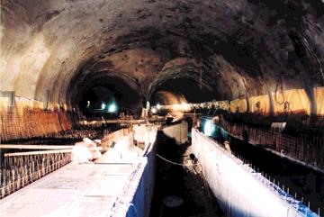


33 ROâNÍK, ã. 4/
34 ROâNÍK, ã. 4/2002 pravdûpodobnosti. Tato metoda vyïaduje pouze dvû hodnoty (body) q ij = q ij ± s ij (kaïdou s pravdûpodobností 0,5), které jsou vybrány pro kaïd vstupní parametr (q ij stfiední hodnota, s ij smûrodatná odchylka q ij ). Odezva je zji Èována pro 2 n kombinací vstupních hodnot. Zji tûné odezvy mají stejnou pravdûpodobnost, a proto není problém jednodu e vypoãítat stfiední hodnotu a rozptyl v sledn ch hodnot. Navíc není problémem stanovení relativní dûleïitosti vstupních parametrû. Odli nou cestou pro sníïení poãtu bûhû programu je pouïití metody v bûru vrstev. Tato metoda je zaloïena na známém rozdûlení vstupních parametrû q ij. Rozmezí tûchto parametrû je rozdûleno na N intervalû q ijh (vrstvy) se stejnou pravdûpodobností a poté je provedeno m náhodn ch v bûrû intervalû (stejnû tak jako náhodn ch hodnot uvnitfi intervalû). Vylep ením tohoto pfiiblíïení je metoda latinsk ch hyperkrychlí. V této metodû je rozmezí vstupních parametrû q ij rozdûleno na N intervalû q ijh (h=1,2,,n), které mají stejnou pravdûpodobnost 1/N. Poãet intervalû N metody latinsk ch hyperkrychlí je stanoven shodnû s celkov m poãtem bûhu programu. Z kaïdého intervalu je hodnota parametru vybrána pouze jednou (tj. je pouïita v jednom a pouze v jednom bûhu programu). JestliÏe je N vysoké, není nutné tuto hodnotu vybírat náhodnû (dle rozdûlení pravdûpodobnosti uvnitfi intervalu), ale je moïné ji stanovit jako tûïi tû intervalu. Speciální forma metody latinsk ch hyperkrychlí obsahuje následující náhodn v bûr intervalû q ijh testovan ch pro jednotlivé bûhy programu pro kaïd náhodn parametr pro kaïdou vrstvu mûïe b t posloupnost cel ch ãísel, reprezentujících náhodnou permutaci ãísel 1,2,,N, asociována s náhodnou permutací vstupních parametrû. Ke generaci tûchto náhodn ch permutací lze vyuïít bûïnou poãítaãovou knihovnu. V sledkem k-tého bûhu programu je velikost deformace X k. Ukázalo se, Ïe metoda latinsk ch hyperkrychlí dává podstatnû men í rozptyl odhadû neï ostatní metody pfii stejném poãtu bûhû poãítaãe N. Experimenty ukazují, Ïe obyãejnû by mûl staãit v bûr N = n (poãet bûhû programu rovn poãtu náhodn ch parametrû). V hodou metody latinsk ch hyperkrychlí je v ak to, Ïe vstupní rozsah kaïdého parametru je zcela pokryt, coï umoïàuje komplexnûj í pfiedstavu o chování odezvy. Na rozdíl od této metody vyïaduje metoda bodov ch odhadû momentû pravdûpodobnosti 2 n bûhû, její v hodou v ak je pomûrnû jednoduché hodnocení relativní dûleïitosti kaïdého parametru, coï je v metodû latinsk ch hyperkrychlí ponûkud komplikovanûj í. Jin pfiístup pro ohodnocení vlivu vstupních parametrû je pouïití fuzzy techniky. Pokud budeme parametry chování horniny brát jako fuzzy (neurãité, rozmazané) hodnoty, mûïeme pfii pouïití fuzzy techniky a kombinace parametrû vygenerovat ãísla, která docela vûrnû pfiedstavují promûnlivost chování horninového masivu a mohou b t pouïita jako vstupní parametry fie ení. Z dûvodu, Ïe fuzzy technika pfiipou tí jistou neurãitost zahrnutou v urãení parametrû, nabízí se její pouïití v aplikaci na indexové klasifikace horninov ch masivû. Jako pfiíklad mûïeme uvést norskou klasifikaci podle indexu Q, kter oceàuje kvalitu horninového masivu empirick m systémem s pûti parametry (v echny parametry jsou vyjádfieny poãtem klasifikaãních bodû: J n poãet puklinov ch systémû J a zvûtrání ploch diskontinuity ãi v plní J r drsnost puklin J w vodní tlak RQD hodnocení masivu dle klasifikace RQD SRF podmínky tlakového projevu horninového masivu. RQD J Vztah pro index Q: Q= r J w J n J a SRF Pro konkrétní aplikaci, kterou uvádí HUDSON HARRISON (1997), paramet- nation of relative significance of the input parameters. Application of the method of selection of layers is a different way how to reduce the number of the program runs. This method is based on a known distribution of input parameters qij. The range of those parameters is divided into N intervals q ijh (layers) with identical probability, then m random samples of intervals are selected (and random samples inside the intervals as well). The Latin hypercubes method is an upgrade of this approximation. In this method, the range of input parameters q ij is divided into N intervals q ijh (h=1,2,,n), having identical probability of 1/N. The number N of the intervals at the Latin hypercubes method is determined identically with the overall number of the program runs. A parameter value is selected from each interval once only (it is used in one and only one program run). If the N is high, this value does not have to be selected randomly (according to the probability distribution within the interval). It can be determined as a gravity centre of the interval. Special form of the Latin hypercubes method contains the following random sampling of the intervals q ijh tested for particular program runs. i.e. for each random parameter, for each layer the sequence of integer numbers representing a random permutation of numbers 1,2,,3,N can be associated with a random permutation of the input parameters. Common computer program library can be used for generation of these random permutations. The result of a kth run of the program is the magnitude of deformation X k. It turned out that the Latin hypercubes method provides substantially lower spread in assessments than the other methods at the same number N of computer runs. Experiments prove that usually a selection N=n (the number of the program runs identical with the number of random parameters) should be sufficient. The advantage of the Latin hypercubes method is the fact that the entry range of each parameter is fully covered. This makes creation of a more complex idea of the response behaviour possible. In contrast to this method, the method of point estimations of probability moments requires 2 n runs. Although, its advantage is comparatively simple assessment of the relative significance of each parameter, which is a little bit more difficult at the Latin hypercubes method. Another attitude towards the assessment of the effect of the input parameters consists in application of the fuzzy technique. If we consider the rock mass parameters to be fuzzy values, we can use the fuzzy technique and a combination of the parameters to generate figures, which represent the rock mass variability quite truly, and can be used as input parameters of the solution. Because of the fact that the fuzzy technique allows certain vagueness in the parameters determination, the idea of its application suggests itself in the field of rock mass index classification. As an example, we can mention Norwegian classification according the Q index, which assesses the rock mass quality by means of an empirical system comprising five parameters (all the parameters are defined by a number of classification points): J n number of joint systems J a weathering of discontinuity planes or filling J r joints roughness J w water pressure RQD rock mass assessment according to the RQD classification SRF RQD J Relationship for the index Q: Q= r J w J n J a SRF For the specific application referred to by HUDSON HARRISON (1997), the RQD and J r parameters fluctuate within certain range, the J w parameter mostly assumes its maximum value, and similarly the Jn parameter assumes its minimum value. Remaining two parameters SRF and J a can assume one value only (they are considered to be constants). We apply the fuzzy technique on the basic relationship for determination of the Q index (Fig. 1). The result will be a fuzzy classification value (in the case of our example the value of 5.8, which originated by means of a combination of individual parameters), and a probability distribution of remaining values. It follows from the non-linear distribution (convex shape) that the Q index will probably assume values less than 5.8, which fact signals an increase in the probabili- Obr. 1 UÏití fuzzy techniky pfii urãení indexu Q (dle HUDSON-HARRISON, 1997) Fig. 1 Application of the fuzzy technique in assessment of the Q index (by HUDSON-HARRISON, 1997)
35 ROâNÍK, ã. 4/2002 ry RQD a J r kolísají v urãitém rozsahu, parametr J w vût inou nab vá své maximální hodnoty a podobnû parametr J n své minimální hodnoty, zb vající dva parametry SRF a J a mohou nab vat jen jedné hodnoty (povaïují se za konstantu). Na základní vztah pro urãení indexu Q aplikujeme fuzzy techniku (obr. 1) a v sledkem bude fuzzy klasifikaãní hodnota (v na em pfiíkladû hodnota 5,8, která vznikla kombinací jednotliv ch parametrû) a pravdûpodobnostní rozdûlení zbyl ch hodnot. Z nelineárního rozdûlení (konvexní tvar) vypl vá, Ïe index Q bude pravdûpodobnû nab vat hodnoty men í neï 5,8, coï signalizuje zvût ení pravdûpodobnosti, Ïe podmínky v horninovém masivu budou hor í, neï by se dalo usuzovat na základû samostatné hodnoty indexu Q. ty that the conditions in the rock mass will be worse than it could be expected on the basis of an isolated value of the Q index. APPLICATION OF THE LATIN HYPERCUBES ON THE MRAZOVKA TUNNEL The excavation of the western tube of the Mrazovka tunnel started towards the end of the year 1999, from the northern portal, towards the south (Fig.2). The western tunnel tube was driven in very difficult geological conditions, mostly in heavily fractured massif of Ordovician clayey and clayey-silty shales, locally replaced by hard quartziferous shales and quartzites. Horizontal face division was designed (top heading-side wall areas-invert). This generally represents a rather simple sequential excavation with primary support by vault, side walls lining and invert. As we know today, this procedure was applied within an about 120m long section from the northern portal only, just under Mrazovka Hill, with not too much good results. Obr. 2 Podéln fiez tunelem Mrázovka v oblasti severního portálu Fig. 2 Longitudinal section through the Mrazovka tunnel, in the North portal area
36 ROâNÍK, ã. 4/2002 APLIKACE METODY LATINSK CH HYPERKRYCHLÍ NA TUNEL MRÁZOVKA RaÏba západní trouby tunelu Mrázovka zapoãala ke konci roku 1999 od severního portálu smûrem k jihu (obr. 2). Západní tunel byl raïen ve velmi obtíïn ch geologick ch pomûrech, pfieváïnû v silnû poru eném masivu ordovick ch jílovit ch a jílovito-prachovit ch bfiidlic, místy vystfiídan ch tvrd mi prokfiemenûl mi bfiidlicemi a kfiemenci. âlenûní ãelby bylo navrïeno horizontální (kalota-jádro-dno), coï obecnû znamená pomûrnû jednoduchou postupnou raïbu s primárním vystrojováním horní klenbou, opûrov mi ãástmi ostûní a spodní klenbou. Jak je jiï dnes známo, byl tento postup raïby aplikován pouze v úseku délky asi 120 m od severního portálu pfiímo pod vrchem Mrázovka, a to s nepfiíli dobr mi v sledky. V posuzovaném profilu km 5,160 (viz. obr. 2) nebyl sice pfiímo zpracován statick v poãet, nechalo se v ak dûvodnû pfiedpokládat, Ïe deformace ostûní a horninového masivu nebudou v Ïádném pfiípadû hor í, neï vykázaly v sledky stanovené nûkolika alternativami matematick ch modelû, proveden mi renomovan mi odborníky (s jejich vlastním uváïením vstupních parametrû a specifick ch pfiedpokladû v poãtu) pro velmi nepfiízniv a obávan profil pod Ostrovského ulicí v km 4,850. V tomto profilu byly osmi matematick mi modely deformace terénu v poãtem stanoveny v rozmezí 42 aï 115 mm, prûmûrná hodnota ãinila 68,5 mm. Projektant správnû na základû proveden ch rozborû navrhl fiadu antipoklesov ch opatfiení pro tunelování pomocí NRTM (sanaãní injektáïe, jehlování, mikropilotové de tníky", mikropiloty pod patou kaloty, v jimeãnû kompenzaãní injektáï). Kombinací tûchto opatfiení dle konkrétních podmínek raïby mûla b t zaji tûna limitní deformace povrchu území ve velikosti 60 mm. Brzy po zaãátku raïby ze severu s horizontálním ãlenûním se zaãaly v obtíïn ch geologick ch pomûrech (fiada za sebou probíhajících tektonick ch poruch, v nichï bylo realizováno nûkolik podpûrn ch opatfiení vãetnû sanaãní injektáïe) projevovat nadmûrné deformace primárního ostûní tunelu a povrchu území nad tunelem, které pfiekraãovaly oãekávané hodnoty deformací stanovené projektem. V km 5,160 se mûfiené poklesy terénu ustálily na hodnotû 166 mm, poklesy masivu ve vrcholu v rubu (zji tûno extenzometrick m mûfiením v daném profilu) na hodnotû 194 mm. V stupy dodateãného matematického modelování tunelu Mrázovka v km 5,160 byly provûfieny metodou latinsk ch hyperkrychlí. K v poãtûm byl pou- Ïit program PLAXIS, kter je zaloïen na metodû koneãn ch prvkû. Vzhledem k raïbû tunelu pomocí NRTM byl vlastní v poãet rozdûlen do nûkolika fází, které vystihují prûbûh pobírání ãelby. Prostorové chování ãela v rubu a jeho vliv na deformace a napjatost masivu bylo v rovinû simulováno speciálním postupem pfii zatûïování v rubu a ostûní (tzv. - metodou) v kaïdém stavu budování konstrukce byl nevystrojen v rub zatíïen tfietinou celkového zatíïení, zbylé dvû tfietiny byly pfiisouzeny ostûní. Pro simulaci chování horninového masivu byl pouïit Mohr-CoulombÛv konstitutivní vztah. Intervaly vstupních parametrû horninového masivu (E def,, c,, ) byly voleny zcela v souladu se závûry inïen rskogeologického prûzkumu. V SLEDKY Z v sledkû statistické studie (tab. 1) vypl vá, Ïe v profilu km 5,160 celkové sedání terénu mûlo s pravdûpodobností 95 % leïet mezi hodnotami 50 mm a 167 mm, celkové poklesy tunelového v rubu ve vrcholu klenby mûly s pravdûpodobností 95 % leïet mezi hodnotami 71 mm a 213 mm. Interval sedání terénu bez poklesû zpûsoben ch prûzkumnou tolou je 41 aï 136 mm, u stropu v rubu 65 mm aï 198 mm. Z porovnání v ech v sledkû (deterministické statické v poãty, mûfiené hodnoty, pravdûpodobnostní anyl za) je zfiejmé, Ïe pravdûpodobnostní anal za lépe prognózuje moïné deformace horninového masivu, které jsou podstatnû závislé na náhodné promûnlivosti vstupních geotechnick ch parametrû, specifick ch pro pouïité konstitutivní vztahy matematického modelu. Nutno konstatovat, Ïe zvût ené deformace, provázející raïbu s horizontálnû ãlenûnou ãelbou, nikde nevedly ke ztrátû stability horninového masivu, kodám na objektech v nadloïí a na povrchu území. Lokální více neï patnácticentimetrové poklesy terénu v lesoparku Mrázovka nebyly prakticky vizuálnû patrné a po asi 120 m raïby byly trvale sníïeny vlivem pfiechodu na vertikální ãlenûní raïby pod pfiípustnou deformaci terénu 60 mm. ZÁVùR Aplikace metody latinsk ch hyperkrychlí vycházela ze tfií základních pfiedpokladû, jejichï platnost mûïe b t diskutabilní (stejná závislost parametrû horniny na základní charakteristice jednotliv ch vrstev horninového masivu, normální rozdûlení pravdûpodobnosti v skytu parametrû horninového masivu, normální rozdûlení vypoãten ch deformací). V pfiípadû nezávislosti parametrû v ak stoupne poãet náhodn ch promûnn ch, a tím také potfiebn poãet v poãtû (napfi. v pfiípadû proveden ch v poãtû by u jednotliv ch modelû poãet potfiebn ch spu tûní v poãtového programu stoupl z pûvodních 5 na 5*8=40). Although the statical analysis had not been carried out directly for the assessed profile at km 5.160, it was possible to reasonably expect that the lining and rock mass deformations would on no account be worse than the deformations proved by the results determined by several alternatives of mathematical models carried out by renowned experts (with the input parameters and specific assumptions of the calculation adopted by their own) for very adverse and feared profile under Ostrovskeho Street at km Eight mathematical models were used for this profile, resulting into the surface deformations computed within a range of 42 to 115 mm, with an average value amounting to 68.5 mm. The design engineer correctly proposed, on the basis of the analyses carried out, a series of anti-subsidence measures for tunnelling by the NATM (saving grouting, spiles, micropile umbrellas, micropiles under the top heading footings, exceptionally compensation grouting). The limiting deformation of the area surface of 60 mm was to be ensured through a combination of those measures, depending on specific conditions of the excavation. Soon after the beginning of the excavation from the north with the horizontal sequencing, excess deformations of the tunnel primary lining and the ground surface above the tunnel started to appear in difficult geological conditions (a series of successive tectonic faults for which several supporting measures were applied, including saving grouting), crossing the expected values of deformations set out by the design. At km 5.160, the measured subsidence of the ground surface stabilised at a value of 166 mm, the rock mass subsidence at the opening crown (determined by extensometer measurement at the given profile) at a value of 194 mm. Outputs of the additional mathematical modelling of the Mrazovka tunnel at km were crosschecked by the Latin hypercubes method. Computations were carried out by PLAXIS software, which is based on the finite element method. Because of the NATM tunnel excavation, the computation was divided into several phases corresponding to the face excavation phases. Spatial behaviour of the tunnel face and its effect on deformations and state of stress of the rock mass was simulated in plane by a special procedure at the excavation and the liner loading (so-called -method) the unsupported excavation in each stage of the structure development was loaded by one third of the total loading, remaining two thirds of the loading were assigned to the liner. Mohr-Coulomb constitutive relationship was used for simulation of the rock mass behaviour. Intervals of the rock mass input parameters (E def,, c,, ) were selected in a full compliance with the conclusions of engineering and geological investigation. RESULTS It follows from the results of the statistical study (Tab. 1) that there was a probability of 95% that the values of total ground surface settlement at km would lie between 50mm and 167mm, and a probability of 95% that the values of total settlement of the tunnel excavation at the vault crown would lie between 71mm and 213mm. The interval of the ground surface settlement, with the settlement caused by the exploration gallery excavation deduced, is 41 to 136 mm, at the excavation roof it is 65 mm to 198 mm. It is obvious from a comparison of all results (deterministic statical calculations, measured values, probabilistic analysis) that the probabilistic analysis provides better prognoses of rock mass deformations possible, which depend substantially on random variability of input geotechnical parameters specific for the applied constitutive relationships of the mathematical model. It must be stated that the increased deformations going along with the horizontally sequenced excavation have never caused a loss of rock mass stability, damage to buildings or structures at the overburden and on the ground surface. Local cases of subsidence in Mrazovka forest park exceeding fifteen centimetres were practically visually unperceivable, and they were, after about 120 m of excavation, permanently reduced under an allowable terrain deformation of 60 mm as a result of transition to the vertical excavation sequence. CONCLUSION The application of the Latin hypecubes method was based on three basic assumptions, whose validity can be disputable (identical relationship between rock parameters and the basic characteristics of individual rock mass layers, normal distribution of the rock mass parameters occurrence probability, normal distribution of computed deformations). But should the rock parameters be independent, the number of random variables as well as the number of computations required would increase (e.g. in the case of the performed computations, the number of runs of the computation program required for individual models would rise from the original 5 to 5*8=40). It is useful for a qualified statistical evaluation of modelling results to apply the Latin supercubes method, which allows, compared to other common statistical methods (the Monte Carlo method, the point estimations of probability moments method, etc.), to achieve substantial savings in the computation time. A more general conclusion can be made on the basis of a comparison of the results obtained by application of the Latin hypercubes method on the Mrazovka tunnel western tube at km with the values measured and obtained by the deterministic computation that it is desirable to carry out at least a partial study of the effect of the rock mass parameters variability on the resulting behaviour of the structure. If the probability of achieving unfavourable values of deformations (or other monitored variables) is high, it is desirable to consider application of other adequate techniques (e.g. another type of the excavation sequencing, grouting, pre-lining systems) already in the designing phase. This paper was elaborated in the framework of the solution of the research project MSM: Development of algorithms of computer mechanics and their application in engineering.
37 ROâNÍK, ã. 4/2002 Ke kvalifikovanému statistickému vyhodnocení v sledkû modelování je v hodné vyuïít metodu latinsk ch hyperkrychlí, která vzhledem k ostatním bûïnû uïívan m statistick m metodám (metoda Monte Carlo, metoda bodov ch odhadû momentû pravdûpodobnosti atd.) umoïàuje zásadní úsporu v poãetního ãasu. Z porovnání v sledkû, které byly získány aplikací metody latinsk ch hyperkrychlí na západní troubu tunelu Mrázovka v km 5,160, s hodnotami mûfien mi a získan mi deterministick m v poãtem lze uãinit obecnûj í závûr, Ïe pfii v poãtu podobnû nároãn ch geotechnick ch konstrukcí je Ïádoucí provést aspoà ãásteãnou studii vlivu promûnlivosti parametrû horninového masivu na v sledné chování konstrukce. Pfii vysoké pravdûpodobnosti dosaïení nepfiízniv ch hodnot deformací (nebo jin ch sledovan ch veliãin) je Ïádoucí zváïit jiï pfii návrhu pouïití adekvátních technologií (napfi. jin typ ãlenûní v rubu, injektáïe, PL- systémy). Pfiíspûvek byl zpracován v rámci fie ení v zkumného zámûru MSM: Rozvoj algoritmû poãítaãové mechaniky a jejich aplikace v inïen rství. LITERATURA/REFERENCES BARTÁK, J. CHMELA, R. HILAR, M. (2001): Modelová anal za nadmûrn ch deformací tunelu Mrázovka v oblasti severního portálu. Zakládání staveb, roã. XIII, ã. 1/2001, str BAÎANT, P. - LIU, K. L. (1985): Random Creep and Shrinkage in Structures: Sampling. Journal of Structural Engineering. ASCE, 111, 5, HILAR, M. (2000): Numerical Analysis of the Supporting Measures with Effect on the Tunnel Deformations (MSc. dissertation). Heriot-Watt University, Edinburgh, U.K. HUDEK, J. (1999): Pfiehled geotechnick ch charakteristik ZTT tunelu Mrázovka km 5,160. Zpráva IG prûzkumu, PUDIS Praha. HUDEK, J. - VOREL, J. (1999): Komplexní zhodnocení inïen rskogeologického prûzkumu pro automobilov tunel Mrázovka. PUDIS Praha. HUDSON, J. A.- HARRISON, J. P.: Rock Engineering Mechanics. Pergamon, UK, 1997, ISBN PRU KA, J. (2001): Metody fuzzy a RES v podzemním stavitelství. Stavební obzor 10, ã. 5/2001, str BARTÁK, J. - HILAR, M. (2001): Program Plaxis. Geotechnika, 2/2000, str BARTÁK, J. - PRU KA, J. - MACHÁâEK, J. - HILAR, M. (2001): Numerical Modelling of Underground Structures. Proceedings of Workshop FSv âvut Praha. Celkové poklesy Total settlement Poklesy toly Gallery settlement Poklesy bez vlivu toly Settlement without the gallery effect V poãet Computation Povrch (mm) Surface level Tunel (mm) Tunnel Povrch (mm) Surface level tola (mm) Gallery Povrch (mm) Surface level Tunel (mm) Tunnel X (prûmûr) (average) s (smûr. odchylka) (standard deviation) 108,60 142,20 20,40 10,40 88,20 131,80 29,41 35,61 5,64 2,33 23,80 33,31 X + 2s (p=95,45%) 167,42 213,42 31,69 15,06 135,81 198,43 X - 2s (p=95,45%) 49,78 70,98 9,11 5,74 40,59 65,17 X + 2s (p=68,27%) 138,01 177,81 26,04 12,73 112,00 165,11 X - 2s (p=68,27%) 79,19 106,59 14,76 8,07 64,40 98,49 VAR X (rozptyl) (standard deviation) 5,69 6,22 2,65 1,75 5,15 6,02 Tab. 1 V sledky pro ZTT km 5,160 Table 1 Results for the WTT km 5,160

38 ROâNÍK, ã. 4/2002 SVETI MARKO PRVNÍ CHORVATSK DÁLNIâNÍ TUNEL RAÎEN NRTM SVETI MARKO THE FIRST CROATIAN HIGHWAY TUNNEL DRIVEN BY THE NATM Ing. ROMAN ABATA, ILF CONSULTING ENGINEERS, s. r. o. ÚVOD Po rozpadu b valé Jugoslávie se v ekonomicky nejvyspûlej ích nástupnick ch státech Slovinsku a Chorvatsku zaãaly investovat znaãné prostfiedky do vybudování moderní dopravní infrastruktury. To bylo vyvoláno zmûnou hlavních dopravních smûrû, zpûsobenou jednak vznikem nov ch státních celkû a zároveà díky poloze v sousedství Evropské unie, se kterou tyto zemû nejvíce obchodují. Preferována je v stavba dálnic, neboè stávající dálniãní síè není schopna pojmout silnû vzrûstající objem zejména silniãní dopravy. Díky hornatému terénu lemujícímu Jadranské pobfieïí je zároveà tfieba vybudovat celou fiadu tunelû. Prvním z nich na území Chorvatska je tunel Sveti Marko, kter se nachází na dálnici Záhfieb Rijeka, asi 15 km západnû od mûsta Karlovac. V EOBECNù Tunel je dlouh 290 m, sestává ze dvou oddûlen ch tunelov ch trub osovû vzdálen ch 30 m, ve kter ch jsou vïdy dva jízdní pruhy. Smûrovû je trasa vedena pfieváïnû v pfiímé, pouze v portálov ch oblastech pfiechází do pfiechodnicov ch obloukû. V kovû probíhají obû trouby ve vrcholovém oblouku o polomûru m, coï pfiineslo jisté komplikace pfii fie ení odvodnûní. Pfiíãn sklon vozovek je 2,5 %. Pikantností tohoto tunelu je skuteãnost, Ïe podchází hfibitov obce Bezjakovo Brdo vãetnû obfiadní sínû. PfieváÏná ãást délky obou trub byla vybudována hornick m zpûsobem, nadloïí se pohybovalo od 2 m do 22 m. Portálové bloky a 36 m délky západní roury byly vybudovány v otevfiené jámû. Vzhledem k malé délce tunelu nebyly nutné Ïádné propojky ani tunelov vodovod s hydranty a tunel není nucenû vûtrán. GEOLOGICKÉ POMùRY A VOLBA TUNELOVACÍ METODY Horninov masiv byl tvofien klastick mi a karbonátov mi sedimenty spodního triasu, pfiekryt mi kvartérními pokryvn mi útvary. Klastické sedimenty pfiedstavovala pestrá série písãit ch dolomitû, hlinit ch slínû a jílovit ch bfiidlic. Karbonátové sedimenty v jejich podloïí tvofiily pfieváïnû vrstvy dolomitû a pískovcû. Hladina podzemní vody se nacházela pod úrovní spodní klenby tunelu. Horniny skalního podloïí byly silnû zvûtralé a jejich mocnost v nadloïí tunelu byla do 17 m. Modul deformace se pohyboval kolem 80 Mpa, Poissonovo ãíslo kolem 0,3, koheze byla 50 kpa a úhel vnitfiního tfiení 25. U kvartérních pokryvû byly parametry je tû hor í. ífika v rubu jedné tunelové roury byla 11 m. Tunel byl vyraïen novou rakouskou tunelovací metodou (NRTM). Celá raïená ãást byla kvûli v e uveden m parametrûm horninového masivu zaji tûna kromû standardního vystrojení NRTM také pfiedstihov mi injektáïními de tníky. Na rozdíl od raïby ve skalních nebo INTRODUCTION Considerable investments in development of a modern traffic infrastructure started after the disintegration of former Yugoslavia in economically most advanced succession states of Slovenia and Croatia. This process was induced by a change in the main directions of traffic caused by the origination of new states and, at the same time, owing to their position neighbouring with the European Union, which these countries have been doing most of their business with. Development of highways is being given priority, as the existing highway network is not capable of coping with the heavily increasing volume of transport carried out predominantly on roads. Due to the mountainous terrain surrounding the Adriatic Sea shore it is necessary to build a series of tunnels. In Croatia, the first of them is the Sveti Marko tunnel, found on the Zagreb Rijeka highway, about 15 km west from Karlovac town. IN GENERAL The 290 m long tunnel consists of two separated double-lane tunnel tubes, with the distance between centres of 30 m. Horizontal alignment is mostly straight, with transition curves at portal areas only. Vertical alignment of the two tubes is a convex curve, on a radius of 25,000 m, causing certain complications in the drainage design. The crossfall of the roadways is 2.5 %. A piquancy of this tunnel is the fact that it passes under a cemetery of Bezjakovo Brdo municipality, including the mortuary-mourning hall. The major part of the tunnel tubes length was built by mining methods. The overburden thickness varied from 2 m to 22 m. The portal blocks and a 36mlong section of the western tube were constructed in open pits. Thanks to the short length of the tunnel, neither cross passages nor a tunnel water distribution with fire hydrants were required, and the tunnel is not ventilated mechanically. GEOLOGY AND SELECTION OF THE TUNNELLING METHOD The rock mass consisted of the Lower Jurrasic clastic and carbonate sediments, overlaid with the Quaternary cover. The clastic sediments were represented by a varied series of sandy dolomites, loamy marls and shales. The carbonate sediments underneath consisted mostly of dolomite and sandstone layers. Water table was found beneath the tunnel invert level. The bedrock was heavily weathered, and its thickness above the tunnel crown was up to 17 m. The modulus of deformation varied around 80 Mpa, Poisson s ratio around 0.3, cohesion was 50 kpa, and the angle of internal friction 25. The parameters of the Quaternary cover were even worse. The width of one tunnel tube cross-section was 11 m. The tunnel was excavated by the New Austrian Tunnelling Method (NATM). In addition to standard NATM support means, the whole mined portion of the tunnel was supported by pre-grouting umbrellas. As opposed to rock or semi-rock excavation under a sufficient cover, it was impossible in this case to expect that the anticipated deformations could be coped with by anchoring. Therefore tough primary lining was designed and the invert closing prescribed at a distance from the face not exceeding 1 diameter of the tunnel tube. EXCAVATION AND EXCAVATION SUPPORT Obr. 1 Pohled na stavební jámu severních portálû a hloubeného úseku Fig. 1 A view of the construction pit for the north portals and the cut-and-cover section PREPARATORY WORK Both tunnel tubes were driven from the northern portal pit. The bottom part of the pit up to a height of 8 m was sloped at a 60 angle and secured with 10-15cm thick shotcrete reinforced with welded wire mesh and 10 m long IBO anchors spaced at 2x2 m centres. The upper part of the pit was provided with 1:1 slopes, without other support measures. A 2 m wide berm was cre-


39 ROâNÍK, ã. 4/2002 poloskalních horninách s dostateãn m nadloïím nebylo moïno poãítat s tím, Ïe by se pfiedpokládané deformace daly zvládnout pomocí kotvení, proto byla zároveà navrïena tuhá primární obezdívka a pfiedepsáno uzavfiení profilu ve vzdálenosti nejdále 1 prûmûr tunelové trouby od ãelby. RAÎBA A ZAJI TùNÍ V RUBU P ÍPRAVNÉ PRÁCE Obû tunelové roury byly raïeny ze severní portálové jámy. Ta byla ve spodní ãásti na v ku 8 m vysvahována ve sklonu 60 a zaji tûna stfiíkan m betonem tlou Èky cm, vyztuïen m ocelov mi svafiovan mi sítûmi a 10 m dlouh mi IBO-kotvami v rastru 2 x 2 m. Horní ãást jámy byla vysvahována ve sklonu 1 : 1 bez dal ího zaji tûní. Mezi dolní a horní ãástí byla vybudována 2 m iroká berma. Pravá (západní) tunelová roura vchází do hory v místû terénní deprese, a proto jsou raïené portály odsazeny v podélném smûru o 36 m. Poãátek raïby levé (v chodní) roury probíhal v sousedství otevfiené jámy pro pravou rouru s nadloïím pokryvn ch útvarû o mocnosti 2 6 m. ífika horninového pilífie mezi v rubem a sousední jámou byla 8 m. JiÏní portálová jáma mûla spí e charakter odfiezu, neboè tunel vychází z hory ikmo ke spádnici portálového svahu a bezprostfiednû na nûj navazuje most. Portály tunelov ch trub jsou v podélném smûru odsazeny o 23 m. Portálové bloky, budované hloubenû, byly o 2 m zataïeny do roz ífieného v rubu raïené ãásti. Spodní ãást portálové jámy byla vysvahována zhruba na v ku tunelû ve sklonu 3 : 1 a zaji tûna kotvením a stfiíkan m betonem se sítûmi jako v pfiedchozím pfiípadû. Vrchní ãást byla vysvahována ve sklonu 1 : 1,5 a mûla jiï definitivní tvar portálového záfiezu. Stfiíkan beton byl po skonãení raïby obloïen kamenn mi bloky, vyskládan mi ve stejném sklonu, které tvofií koneãnou podobu portálového záfiezu. P EDSTIHOVÉ INJEKTÁÎNÍ DE TNÍKY Cel tunel byl budován v nepfiízniv ch geologick ch podmínkách. Pro zaji - tûní bezpeãné raïby byly proto v celé jeho délce pouïity de tníky z mikropi- ated between the lower and upper level. The right-hand (western) tunnel tube cuts into the mountain at a location of a terrain depression. Therefore the mined portals are relatively offset by 36 m. The left-hand (eastern) tube excavation beginning took place in the vicinity of the open pit for the righthand tube, with the overlaying cover 2-6 m thick. The rock pillar between the excavation and the neighbouring pit was 8m wide. The southern portal pit was rather a half-cutting as the tunnel emerges from the mountain skew to the line of maximum incline of the portal slope, and is directly followed by a bridge structure. The portals of the tunnel tubes are relatively offset by 23 m. The cut-and-cover portal blocks extended to the enlarged excavation of the mined part. The bottom part of the portal pit was sloped roughly up to the tunnels height level, at a 3:1 slope, and supported by anchors and shotcrete with mesh, identically with the above case. The upper part sloped at a 1:1.5 gradient was given the definitive shape of the portal cutting. When the excavation had been finished, the sprayed concrete surface was clad with stone blocks placed at the same inclination, forming the final appearance of the portal cutting. PRE-GROUTING UMBRELLAS The whole tunnel was built under unfavourable geological conditions. Therefore, to secure safe excavation, micropile umbrellas were applied along the whole tunnel length consisting of perforated steel pipes 115 mm in diameter, with 6 mm wall thickness, inserted into 123 mm-diameter bore holes. Individual sections were 15m long, with a 3 m overlapping. The micropiles were drilled on 40cm centres. To allow trouble-free drilling of individual sections, the excavation had to be enlarged every 12 m so that the micropile axis was offset from the following excavation face by 17 cm, and an additional minimally 30 cm wide space remained above for the drilling gear. When the drilling and installation of the pipes in a particular section had been completed, the annulus between the pipe and the borehole wall was filled with mortar. A sleeve created in this manner prevented the injection Obr. 2 Podéln geologick fiez tunelem Sveti Marko Fig. 2 Longitudinal geological section through the Sveti Marko tunnel Obr. 3 Roz ífiení v rubu v místû navrtání dal í sekce injektáïního de tníku Fig. 3 The excavation enlargement at the place of drilling for next section of the grouting umbrella

40 ROâNÍK, ã. 4/2002 lot, sestávající z ocelov ch perforovan ch trubek o prûmûru 115 mm a tlou Èce stûny 6 mm, osazovan ch do vrtû o prûmûru 123 mm. Délka jednotliv ch sekcí byla 15 m, podéln pfiesah 3 m. Osová vzdálenost jednotliv ch mikropilot v místû navrtání byla 40 cm. Aby bylo moïno jednotlivé sekce bez problémû navrtat, bylo nutno provést na kaïd ch 12 m roz ífiení v rubu tak, aby osa mikropiloty byla od líce následujícího v rubu o 17 cm odsazena a nad ní zbylo je tû min. 30 cm místa ke stávajícímu líci stfiíkaného betonu pro vrtné soustrojí. Po navrtání a osazení trubek v kaïdé sekci byla spára mezi trubkou a stûnou vrtu vyplnûna maltou, která po zatvrdnutí vytvofiila objímku, zabraàující pronikání injekãní smûsi zpût k ústí vrtu. Poté byly jednotlivé mikropiloty pfiíslu né sekce zainjektovány. Podle geometrického uspofiádání mikropilot byly pouïity dva typy de tníkû. Prvním z nich byl de tník ve tvaru vertikálnû pfiev eného vûjífie s mikropilotami umístûn mi pouze v klenbû kaloty. V hodou tohoto fie ení je zachování geometrie v rubu pfii jeho pfievy ování, pfiiãemï se mûní pouze v ka kaloty. V tomto pfiípadû lze pro celou délku sekce pouïít stejné vyztuïovací oblouky, pouze s promûnnou délkou v oblasti paty kaloty. Vystrojení v rubu bylo v tomto pfiípadû podle potfieby doplnûno jehlováním po stranách pfiedstihového de tníku. Tento typ de tníku byl pouïit pro lep í geotechnické parametry horninového prostfiedí. Druh m typem byl de tník ve tvaru radiálnû rozbíhavého vûjífie. Mikropiloty byly v tomto pfiípadû navrtány aï do odklonu 57 od svislé osy profilu, kde zaãíná roz ífiení paty kaloty. Geometrie kaloty i opûfií byla promûnná v závislosti na rozevfiení vûjífie. Tento typ de tníku byl pouïit pro raïbu v hor ích geologick ch pomûrech. T ÍDY V RUBU RaÏen úsek obou tunelov ch trub byl rozdûlûn na základû statické anal zy do dvou tfiíd v rubu. Typ 1 oznaãoval tfiídu v rubu s vertikálnû pfiev en m typem injektáïního de tníku, která byla uplatnûna ve stfiední ãásti tunelu. Typ 2 oznaãoval tfiídu v rubu s radiálnû rozbíhav m typem injektáïního de tníku, která byla pouïita pro oblasti s niï ím nadloïím. Pro pfiiportálové oblasti byly navíc pouïity doplàující vystrojovací prvky. Vzhledem k dan m fyzikálnû-mechanick m vlastnostem horniny nebylo nutno pouïít trhacích prací a raïba byla provádûna pomocí tunelového bagru nebo hydraulického kladiva. Ve tfiídû v rubu typ 1 byla raïba rozãlenûna na kalotu, jádro a dno se spodní klenbou. Délka zábûru byla 1 m a profil byl uzavírán v sedmém zábûru od ãelby. V rub byl zaji tûn kotvením po stranách pfiedstihového de tníku, v pfiípadû potfieby i jehlováním, a 30 cm siln m primárním ostûním ze stfiíkaného betonu, vyztuïen m dvûma ocelov mi svafiovan mi sítûmi a pfiíhradov mi v ztuïn mi oblouky. Spodní klenba byla rovnûï zaji tûna stfiíkan m betonem tlou Èky 30 cm se dvûma sítûmi. Pro kotvení byly zvoleny buì IBOkotvy, nebo SN-kotvy podle toho, zda mûlo prostfiedí charakter horniny, nebo spí e ulehlé zeminy. V kalotû byla délka kotev 3 4 m, v jádru 4 6 m vzhledem k pomûrnû velkému polomûru zakfiivení, kter vznikl v dûsledku pfievy ování profilu. Ve tfiídû v rubu typ 2 byla raïba rozãlenûna stejnû jako v pfiedcházejícím pfiípadû, délka zábûru i vystrojení byly shodné. Rozdíl byl v tom, Ïe díky vût í ífice injektáïního de tníku se v kalotû kotvilo i mezi pfiedstihové mikropiloty. V závislosti na v sledcích geotechnick ch mûfiení bylo v pfiípadû potfieby grout from flowing back to the hole mouth. Subsequently the individual micropiles of the particular section were grouted. Two umbrella types were used, depending on the geometrical configuration of the micropiles. The first one was a vertically surmounted fan-shaped umbrella with micropiles placed at the top heading vault only. The advantage of this solution is that the excavation geometry is maintained at its surmounting, while the top heading s height only varies. In this particular case, identical support arches can be used within the whole section length, whose legs length only varies in the springing area. Spiling at the sides of the pregrouted umbrella complemented the excavation support in this particular case on an as needed basis. This umbrella type was used in case of more favourable geotechnical parameters of the rock mass. A radially diverging fan-shaped umbrella was the other type. In this case, the micropiles were drilled with a deflection from the vertical axis of the profile up to 57, where the top heading s footing enlargement begins. The cross section of the top heading and the side wall areas varied depending on the fan opening. This umbrella type was used for excavation in worse geology. EXCAVATION CLASSES The mined sections of the two tunnel tubes were divided into two excavation classes. Type 1 denoted an excavation class with the vertically surmounted type of the grouting umbrella, which was applied in the central part of the tunnel. Type 2 denoted an excavation class with the radially diverging type of the grouting fan, which was utilised for areas with lower overburden. In addition, complementing elements were used for portal areas. Blasting operations were not needed thanks to the given physical and mechanical properties of the rock. Tunnel excavator or hydraulic breaker were sufficient for the excavation. For the excavation class Type 1, the excavation was phased into top heading, core and invert sequence. The round length of 1m was applied, and the profile was closed by invert in the seventh round from the face. The excavation was supported by anchors at the sides of the pre-grouting umbrella, even by spiling if required, and a 30 cm-thick primary shotcrete lining reinforced by two layers of welded mesh and lattice girders. Invert was also supported by shotcrete 30cm thick, with two layers of mesh. IBO-type anchors or SN-type anchors were used for anchoring, depending on the environment character being either rock or rather settled soil. The anchors were 3 4 m long in the top heading, while for the core excavation, due to a relatively large radius of the lining curvature originating as a result of the profile surmounting, a length of 4 6 m was needed. For the excavation class Type 2, the excavation was phased identically as in the previous case, the round lengths and the support were the same. The difference consisted in anchors being placed even between the advanced micropiles, due to the greater width of the grouting umbrella. Depending on geotechnical measurement results, the support for both excavation classes was complemented by a wedge support core, shotcrete applied on the face, by widening of the top heading footing, or also micropiles at the top heading footing, or even securing the top heading invert by sprayed concrete. In the areas close to the portals, the Type 2 excavation class was applied, complemented by the face support using 8 m-long IBO-anchors, while the above-mentioned complementing support elements application was com- Obr. 4 Pfiíãn fiez tunelem s vertikálnû pfiev en m injektáïním de tníkem Fig. 4 Cross section through the tunnel with vertically surmounted grouting umbrella


41 ROâNÍK, ã. 4/2002 vystrojení v obou tfiídách v rubu doplnûno ãelbov m klínem, zaji tûním ãelby stfiíkan m betonem, roz ífiením paty kaloty, pfiípadnû i mikropilotami v patû kaloty, nebo dokonce spodní klenbou v kalotû, zaji tûnou stfiíkan m betonem. V pfiiportálov ch oblastech byla pro raïbu pouïita tfiída v rubu typ 2, doplnûná o zaji tûní ãelby 8 m dlouh mi IBO-kotvami, pfiiãemï doplàující prvky vystrojení z pfiedchozího odstavce byly pouïity povinnû. Tlou Èka stfiíkaného betonu primární obezdívky byla po celém obvodu profilu zesílena na 35 cm, délka v ech kotev byla zvût ena na 6 8 m a jejich rastr zhu tûn. Schéma pobírání bylo v tomto pfiípadû upraveno tak, Ïe v rub jádra tvofiil v podstatû prodlouïení ãelbového klínu z kaloty aï na úroveà poãvy opûfií. Profil byl uzavírán rovnûï v sedmém zábûru od ãelby. Na poãátku raïby levé tunelové roury byly kotvy na pravé stranû kaloty provrtány aï do sousední otevfiené stavební jámy pro pravou tunelovou rouru, kde na nû byly osazeny kotevní hlavy i z druhé strany a poté staïeny tak, Ïe tvofiily v podstatû pfiedpjatou v ztuï horninového pilífie. GEOTECHNICKÁ Mù ENÍ Pro sledování deformací horninového masivu byl vypracován program geotechnick ch mûfiení. Ta probíhala jednak na povrchu, v oblasti pfiedpokládané poklesové kotliny, a také v tunelov ch rourách. Na povrchu byly umístûny v osách obou trub mûfiické body v odstupu po 25 m, pomocí nichï bylo mûfieno sedání v ãase, v závislosti na prostorové poloze ãelby. TatáÏ mûfiení pulsory. The primary lining shotcrete thickness increased to 35 cm around the full section, the length of all anchors rose to 6 8 m, and their spacing became denser. The excavation sequence was modified in this case. In essence, the core excavation consisted in the excavation of the wedge support core in the top heading extending down to the core bottom. The profile was also closed at the seventh round from the face. At the beginning of the left tunnel tube excavation, the anchors on the right-hand side of the top heading were drilled through, up to the adjacent open construction pit excavated for the right-hand tunnel tube. Face plates were mounted on those anchors even from the opposite side. The anchors were tensioned then, forming in substance a pre-tensioned support of the rock pillar. GEOTECHNICAL MEASUREMENTS A programme of geotechnical measurements was developed for the monitoring of the rock mass deformation. The measurements were carried out both on the surface, within the anticipated settlement trough area, and also inside the tunnel tubes. Survey points on the surface were placed at 25 m spacing above the centre lines of the two tunnel tubes. They allowed measurement of the settlement changing with time, depending on the spatial position of the face. The same measurements were carried out inside the tunnels too, using survey points installed at about 12 m spacing in the vault (denser at portals). In addition, five-point convergence stations were established in the tunnels every m, where deformations and convergences Obr. 5 Pfiíãn fiez tunelem s injektáïním de tníkem ve tvaru radiálnû rozbíhavého vûjífie Fig. 5 Cross section through the tunnel with radially diverging fan-shaped umbrella Obr. 6 Pfiíãn fiez tunelem s vystrojením v rubu v pfiiportálov ch oblastech Fig. 6 Cross section through the tunnel with the excavation support in areas close to portals

42 ROâNÍK, ã. 4/2002 probíhala i v tunelech, kde byly v klenbû osazeny mûfiické body po asi 12 m (u portálû hustûji). V tunelech byly dále osazeny po m pûtibodové konvergenãní profily, kde byly mûfieny deformace a konvergence primární obezdívky, resp. horninového masivu. Kromû tûchto mûfiení byly navíc pouïity také inklinometry. Pût z nich bylo umístûno pfiímo v tunelov ch rourách a dal ích 13 (z toho 6 ks délky 20 m a 7 ks délky 30 m) na povrchu. Jednalo se o kombinované inklinometry, schopné mûfiit deformace v rûzn ch hloubkách v jednom vrtu zároveà. Tímto zpûsobem bylo chování horninového masívu dostateãnû pfiesnû sledováno a v sledky mûfiení byly obratem zohledàovány pfii volbû vhodného mnoïství a typu vystrojovacích prostfiedkû. DEFINITIVNÍ OSTùNÍ SEKUNDÁRNÍ OBEZDÍVKA RAÎENÉ âásti Na základû v sledkû statick ch v poãtû byla v raïené ãásti pouïito ostûní z prostého betonu, tlou Èky min. 30 cm. V oblasti opûfií, kde jsou vy í ohybové momenty a zároveà vet í polomûr profilu, byla tato tlou Èka témûfi o polovinu zvût ena. V dûsledku roz ifiování profilu pfii raïbû, nutného pro osazování jednotliv ch sekcí injektáïních de tníkû, v ak ve skuteãnosti dosahovala tlou Èka sekundárního ostûní aï 1 m. Spodní klenba je v celé raïené ãásti z prostého betonu, v ose tunelu dosahuje tlou Èky 1 m a pod základov mi pasy asi 40 cm. Samotné základové pasy, zaji Èující pfienos napûtí mezi horní a spodní klenbou, jsou prûbûïné, z prostého betonu, iroké 120 cm a vysoké 40 cm. Standardní délka jednotliv ch blokû betonáïe byla 12 m. VÏdy první blok v hofie od raïeného portálu, resp. tfii bloky levé tunelové roury v sousedství otevfiené jámy pro pravou rouru byly konstrukãnû vyztuïeny. Spáry mezi jednotliv mi bloky byly do hloubky 8 cm od líce obezdívky opatfieny nábûhov m roz ífiením a vyplnûny elastomerov m kompresním provazcem. PORTÁLY A HLOUBENÁ âást V echny ãtyfii portálové bloky, jakoï i tfii bloky vybudované v otevfiené jámû, byly dimenzovány na plné zatíïení zpûsobené následn m pfiesypáním. Statick m v poãtem bylo navrïeno Ïelezobetonové ostûní tlou Èky 60 cm, jejíï vnitfiní líc koresponduje se sekundárním ostûním v raïené ãásti. Vnûj í líc je paralelní s vnitfiním aï do místa svislé tangeny v opûfií, odkud pokra- of the primary liner or the rock mass were measured. Apart from the above measurements, also inclinometers were used. Five of them were positioned directly inside the tunnel tubes, while additional 13 pieces (out of that 6 pcs 20m long and 7 pcs 30m long) were installed from the surface. They were combined inclinometers capable of measuring deformations at various depths in one borehole simultaneously. This procedure allowed sufficiently accurate monitoring of the rock mass behaviour. In the turn, the measurement results were taken into consideration in the process of selection of suitable amount and type of the means of support. FINAL LINER SECONDARY LINING OF THE MINED PART Based on the results of structural analysis, a minimally 30 cm-thick mass concrete lining was designed. In the side wall area, where bending moments are higher and the cross-section radius is bigger, the thickness was increased by nearly one half. As a matter of fact, the secondary lining thickness reached 1m due to the cross-section enlargement carried during the excavation work to make the installation of individual sections of the grouting umbrellas possible. The invert is from mass concrete within the whole mined part. Its thickness reaches 1m on the tunnel axis, and about 40 cm under the strip footing. The strip footings themselves, securing the stress transfer between the vault and invert, are continuous, from mass concrete, 120 cm wide and 40 cm high. Standard length of individual casting blocks was 12 m. Each first block behind a mined portal, and three blocks of the left-hand tunnel tube found next to the open pit for the right-hand tube, were provided with concrete reinforcement. The joints between individual blocks had a tapered groove 8cm deep in the liner s internal surface, filled with an elastomer compression rope. PORTALS AND THE CUT-AND-COVER PART All the four portal blocks as well as the three blocks built in the open pit, were designed to withstand full loading by the subsequent backfill. The structural analysis ensued into the design of the 60cm thick reinforced concrete envelope, whose internal surface corresponds with the secondary lining used in the mined part. The external and internal surfaces are parallel up to Obr. 7 Pohled na severní portály po dokonãení betonáïe Fig. 7 View of the north portals after completion of concrete casting


43 ROâNÍK, ã. 4/2002 ãuje svisle dolû. Základové pasy jsou na vnitfiní stranû provedeny shodnû s raïenou ãástí a na vnûj í stranû vytaïeny aï k vnûj ímu líci horní klenby. Spodní klenba je na rozdíl od raïené ãásti prohloubena a rovnûï vytaïena aï k vnûj ímu líci základového pasu. V tomto místû má tlou Èku 20 cm a v ose tunelu dosahuje 132 cm. Spodní klenba jakoï i základové pasy jsou vybudovány z monolitického Ïelezobetonu. Portálové bloky jsou v podélném smûru sefiíznuty ve sklonu 1 : 1. Tím bylo dosaïeno opticky vyváïeného pfiechodu od volné trasy dálnice do tunelu. Portálov vûnec tvofií zborcená plocha stejné tlou Èky jako zbytek portálového bloku (60 cm), která je v kaïdém bodû kolmá na oba líce ostûní. Zaãíná vïdy v místû, kde je tlou Èka obezdívky jiï konstantní, tj. asi 1,5 m nad vozovkou, kde má v podélném smûru sklon 45 a pokraãuje do klenby portálu, kde je svislá. Toto fie ení bylo zvoleno proto, Ïe jej lze velmi snadno vybednit pomocí dfievûn ch prken, osazen ch kolmo na bednicí vûz v poïadovaném podélném sklonu fiezu. Vrchol klenby tunelu je tak asi o 5,3 m blíïe smûrem k hofie. V oblasti roz ífiené opûry portálu, podél svislého vnûj- ího líce ostûní, je ãelní strana portálu rovnûï svislá. Portálové i hloubené bloky byly následnû pfiesypány zeminou a terén byl v bezprostfiedním okolí patfiiãnû vymodelován. U severních portálû byla vyplnûna i terénní deprese a portály obou tunelov ch trub umístûny oproti pfiedcházejícímu stupni dokumentace do stejného staniãení. Tím bylo docíleno architektonicky harmoniãtûj ího perspektivního pohledu. V KLENKY V kaïdé tunelové roufie byly vybudovány vïdy na levé stranû ve smûru jízdy dva v klenky pro elektrotechnická zafiízení ífiky 160 cm, hloubky 170 cm a v ky nad nouzov m chodníkem 225 cm. Dále byly vïdy po 48 m oboustranû zfiízeny v klenky pro ãistûní drenáïe tunelu. Ty jsou hluboké 40 cm, iroké 140 cm, vycházejí z líce vnitfiního ostûní nábûhem o v ce asi 2 m a je jich dohromady 9 párû. V echny v klenky jsou situovány v raïené ãásti tunelu. V klenky pro ãistûní drenáïe jsou díky staticky v hodné geometrii provedeny pouze z prostého betonu a v klenky pro elektrotechnická zafiízení jsou ze Ïelezobetonu. Umístûní nevyztuïen ch v klenkû pro ãistûní drenáïe v tunelovém bloku bylo zvoleno s ohledem na smr Èování betonu a s tím spojen m tvofiením trhlin. Nejvût í napûtí ze smr Èování vznikají ve stfiedu délky tunelového bloku, a protoïe v klenky byly betonovány zároveà s definitivní obezdívkou, Obr. 8 Tunelov blok s obûma druhy v klenkû Fig. 8 Tunnel block with both types of niches the location of the vertical tangent, from which place it becomes vertical. Foundation strips are carried out identically with those of the mined part on the internal side, while they continue up to the external face of the upper vault on the external side. The invert is, as opposed to the mined part, deepened and also extended up to the external face of the foundation strip. It is 20cm thick at this place, while the thickness reaches 132 cm on the tunnel axis. The invert and strip foundation are from mass concrete. The portal blocks are cut skew, reposing at 1:1. Thanks to this measure an optically balanced transition of the highway route from the open space to the tunnel was achieved. The portal collar has a twisted surface perpendicular at each point to both faces of the liner. Its thickness is identical with the thickness of the remaining part of the portal block, i.e. 60cm. Its beginning is always at such a location where the liner s thickness is constant, i.e. about 1.5m above the carriageway, where its longitudinal gradient is 45, and continues up to the portal crown where it is vertical. This solution was adopted because the formwork can be easily assembled using wood planks fixed perpendicular to the form traveller, at the longitudinal slope required at the particular cross section. Thus the summit of the tunnel vault is about 5.3m closer to the mountain. In the area of the widened portal side wall, along the vertical extrados of the liner, the front side of the portal is also vertical. The portal blocks and cut-and-cover blocks were subsequently covered with soil backfill, and the surface in the close vicinity was suitably modelled. A terrain depression at the northern portals was also backfilled, and, contrary to the preceding level of design documentation, the portals of the two tunnel tubes were placed to identical chainages. An architectonically more harmonic perspective view was achieved in this manner. NICHES Two niches for electrical equipment were built in each tunnel tube. The 160cm wide, 170 cm deep and 225 cm high (measured from the emergency pavement level) niches are on the left-hand side of the particular tunnel tube (viewed looking in the traffic direction). Further, niches for the tunnel drainage cleaning up were provided every 48 m, on both sides (9 pairs in total). The niches are 40 cm deep and 140c m wide. Their inclined back face starts from the 40 cm depth and ends at the internal lining intrados at a height of about 2 m. All the niches are situated in the mined part of the tunnel. Owing to their geometry, advantageous in terms of structural analysis, the drainage cleaning niches could be built in mass concrete only, while the niches for electrical equipment are from reinforced concrete. Locations of the non-reinforced drainage cleaning niches within a tunnel block were chosen with respect to concrete shrinkage and related creation of fissures. The highest shrinkage stresses originate at the midpoint of a tunnel block length. As the niches were cast together with the final liner, it is inappropriate to place them just to the centre of the block. Namely it could happen that a network of cracks would originate around in the mass concrete of the lining, whose width could exceed the prescribed limit. For that reason a distance of the niche s axis 3 m from the joint between the casting blocks was chosen, leaving about 2 m length of standard secondary liner between the niche wall and the block joint. The larger niches for electrical equipment were, similarly to the adjacent surrounding area of the internal liner, reinforced, and the reinforcement resolved the issue of shrinkage fissures creation. For that reason their axis was at a distance of 5 m from a joint between two blocks, allowing so maintenance of the embedment lengths of longitudinal reinforcing bars. An abnormal case occurred within one of the blocks, containing both kinds of the niches on one tunnel side. There was an axial distance of 4m between the niches, with the above-mentioned distances of 4 m kept. Obr. 9 Pohled na vytaïenou izolaci z posledního roz ífiení raïené ãásti na jiïní portál Fig. 9 View of the waterproofing membrane protruding from the last enlargement of the mined part to the South Portal Obr. 10 Pohled na tunelovou drenáï u portálu (vpravo) a odvodnûní vrstev vozovky (vlevo) Fig. 10 View of the tunnel drainage at a portal (right), and drainage of the sub-base courses (left)


44 ROâNÍK, ã. 4/2002 není vhodné je umístit právû do stfiedu bloku. Mohlo by se totiï stát, Ïe se v prostém betonu ostûní kolem v klenku vytvofií síè trhlin, jejichï ífika by mohla pfiekroãit pfiedepsanou mez. Z toho dûvodu byla zvolena poloha 3 m od spáry mezi bloky betonáïe k ose v klenku. Tím zbylo mezi stûnou v klenku a blokovou spárou asi 2 m délky standardního sekundárního ostûní. Vût í v klenky pro elektrotechnická zafiízení byly, tak jako bezprostfiední oblast vnitfiního ostûní kolem nich, vyztuïeny a tato v ztuï pokryla i tvofiení smr Èovacích trhlin. Proto byla jejich osa vzdálena 5 m od spáry mezi bloky, s ohledem na kotevní délky v ztuïe v podélném smûru. V jednom z blokû nastal anomální pfiípad, neboè zde byly na jedné stranû tunelu umístûny oba druhy v klenkû. Osová vzdálenost mezi nimi byla pfii dodrïení v e popsan ch vzdáleností 4 m. IZOLACE A ODVODNùNÍ TUNELU IZOLACE Vzhledem k dostateãné hloubce hladiny podzemní vody byly obû tunelové roury drenáïovány. Izolovat bylo proto tfieba pouze proti sráïkov m vodám, které prosakují skrz nízké a propustné nadloïí. Bylo pouïito mezilehlé izolace z plastov ch pásû tlou Èky 2 mm, umístûn ch vïdy od klenby tunelu po boãní drenáïe, nacházející se na vnûj í stranû základov ch pasû. Izolace byla upevnûna na vyrovnávací vrstvu z jemnozrnného stfiíkaného betonu, která kopírovala vnitfiní líc primárního ostûní a vyrovnávala povrchové nerovnosti. Izolace pak byla osazena a svafiena tak, Ïe respektovala roz ífiení v rubu nutná pro zhotovení pfiedstihov ch de tníkû a cel prostor uvnitfi byl aï k líci sekundárního ostûní vyplnûn betonem. TUNELOVÁ DRENÁÎ Pro odvedení vod prosakujících horninov m masívem ke konstrukci tunelu byly pro kaïdou tunelovou rouru pouïity dvû perforované plastové trubky DN150, podkovovitého tvaru s rovn m dnem. Umístûny byly do betonového loïe mezi základov mi pasy a primární obezdívkou a obsypány fiíãním tûrkem. Vzhledem k tomu, Ïe je tunel veden ve vrcholovém oblouku s polomûrem m, bylo nutno umístit drenáïní trubky tak, aby bylo dosaïeno min. podélného spádu 0,5 %. To vedlo k tomu, Ïe uprostfied tunelu je drenáï umístûna o nûco v e a u portálû naopak o nûco níïe, neï by byla optimální poloha. Vzhledem k tolerancím v prostoru pro vedení drenáïe je v ak toto fie ení moïné. achty pro ãistûní drenáïe jsou situovány po 48 m, coï je i pfies minimální spád dostateãná vzdálenost, aby bylo moïno drenáï udr- Ïet funkãní po celou dobu Ïivotnosti tunelu. KaÏdá achta sestává ze dvou ãisticích otvorû o rozmûrech 60 x 40 cm, umístûn ch za sebou v podélném smûru a pfiekryt ch litinov mi poklopy s tûsnûním proti pronikání kapalin. U portálov ch a hlouben ch blokû byla drenáï vyvedena na vnûj í stranu konstrukce a místo zásypu tûrkem byl pouïit filtraãní beton. ODVODNùNÍ VNIT NÍHO PROSTORU TUNELU Ve vnitfiním prostoru tunelu jsou instalovány dva druhy odvodnûní. Jedním je odvodnûní podkladních vrstev vozovky a druh m odvodnûní vod z vozovky, nouzov ch chodníkû a stûn tunelu. V prvním pfiípadû se jedná o ãistou vodu, která mûïe nastoupat odspodu pfies neizolovanou spodní klenbu, pfiípadnû proudit podkladními vrstvami vozovky od portálû a ve druhém pfiípadû jde o pinavou vodu, která je do tunelu zanesena buì provozem vozidel, nebo vodu pouïitou pro ãistûní tunelu. Odvodnûní podkladních vrstev vozovky bylo fie eno podobnû jako u tunelo- TUNNEL WATERPROOFING AND DRAINAGE WATERPROOFING With respect to a sufficient depth of the water table, it was possible to drain both tunnel tubes. Therefore it was necessary to protect the structure against rain water only, seeping through the low and permeable overburden. Intermediate waterproofing membrane 2mm thick was applied, installed from the tunnel crown to the side drains found on the outer side of the strip foundation. The membrane was fixed on a levelling layer of fine-grained shotcrete, copying the internal face of the primary liner and removing the surface roughness. The membrane was installed and welded in a manner respecting the excavation enlargements needed for execution of the pregrouting umbrellas, and the whole space up to the secondary liner s face was filled with concrete. TUNNEL DRAINAGE Two perforated, horseshoe-shaped pipes DN150 with flat bottom, were used for each tunnel tube to evacuate water seeping through the rock mass to the tunnel structure. They were placed in concrete bed between the foundation strips and primary liner, and backfilled with pebble. Due to the fact that the tunnel alignment is a convex curve, on a radius of 25,000 m, the drainage pipes had to be placed so that the drainage gradient was not less than 0.5%. This resulted into the drainage position a little higher at the tunnel middle, and a little lower at the portals than an optimal position would have been. Although, this solution is viable thanks to the tolerances in the space available for the drainage routing. The drainage cleaning manholes are situated at intervals of 48 m. This distance is, despite the minimal gradient, satisfactory for keeping the drainage operational for the whole lifetime of the tunnel. Each manhole consists of two cleaning holes 60x40 cm, positioned in tandem in the drainage direction, and covered with cast-iron covers sealed against penetration of liquids. At the portal blocks and cut-and-cover blocks, the drainage was routed to the external side of the structure. Filtration concrete was used for the backfill instead of pebble. DRAINAGE OF THE TUNNEL INTERIOR Two drainage systems are installed in the tunnel interior. One system is the drainage of the sub-base courses, the other one is the drainage of water from the carriageway, emergency pavements and tunnel walls. The former system evacuates clean water, which can rise from the bottom through the uninsulated invert or flow through the sub-base courses from the portals. The latter system deals with dirty water, brought to the tunnel either by the traffic, or water used for the tunnel cleaning. The sub-base courses drainage was solved similarly to the tunnel drainage, i.e. by horseshoe shaped plastic perforated pipe DN150 with flat bottom. A levelling concrete layer at a 2.5 % crossfall was cast on the invert, whose lower edge the pipe was embedded on. The drainage is connected to the cleaning manholes on the side tunnel drainage. It is also cleaned up from these manholes. At the portals, both this drainage and the tunnel drainage discharge to a seepage pit. To evacuate the dirty water, a slot channel combined with a curb was installed at the right edge of the road (viewed looking in the traffic direction). The horizontal slot is 3 cm wide, and its position is at the road edge, next to Obr. 11A Prefabrikát tûrbinové odpadní roury s otevfienou tûrbinou Fig. 11A Precast unit of the slot channel, with open slot Obr. 11B Dtto s uzavfienou tûrbinou Fig. 11B Ditto with the closed slot Obr. 12 Prefabrikát horní ãásti syfonu tûrbinové odpadní roury s nornou stûnou Fig. 12 Precast unit of the upper part of the interceptor on the slot channel with the baffle wall
45 ROâNÍK, ã. 4/2002 vé drenáïe plastovou perforovanou trubkou DN150, podkovovitého tvaru s rovn m dnem. Na spodní klenbu byla vybetonována vrstva vyrovnávacího betonu s pfiíãním spádem 2,5 %, do které byla trubka na spodním okraji osazena. DrenáÏ je svedena vïdy po 48 m do ãisticích achet boãní tunelové drenáïe, odkud je také ãistûna. U portálû pak je tato drenáï odvedena spolu s tunelovou drenáïí do vsakovací jámy. Pro odvedení pinav ch" vod byla osazena vïdy u pravého okraje vozovky ve smûru jízdy tûrbinová odpadní roura, kombinovaná s obrubníkem. tûrbina je iroká 3 cm a je umístûna vodorovnû na kraji vozovky pfied obrubníkem. Pro v poãet kapacity odvodnûní byl proveden hydraulick v poãet. Vzhledem k nízkému podélnému spádu bylo akceptováno fie ení odvedení vody s ãasov m zpoïdûním. To znamená, Ïe hlavním kritériem bylo rychlé odvodnûní plochy vozovky, pfiiãemï vlastní odtok vody uvnitfi tûrbinové roury je rozloïen na del í ãasové období. Aby bylo v pfiípadû nehody a v toku hofilav ch látek zabránûno hofiení uvnitfi tûrbinové roury, byly v závislosti na podélném sklonu po kaïd ch m osazeny syfony a tûrbina vïdy 9 m pfied a za syfonem uzavfiena. Plocha tûrbinové roury byla zvolena s ohledem na nízk spád a syfony 514 cm 2. Podmínkou bylo, Ïe nesmí dojít ke zpûtnému vytékání hromadící se kapaliny zpût na vozovku. Tomu zabraàuje uzavfiení tûrbiny pfied syfonem. Vzdálenost mezi syfony vymezuje spolu s plochou vtokové tûrbiny potfiebnou kapacitu pro odvedení pfiedepsaného mnoïství litrû kapaliny v poïadovaném ãase 20 min., pfiiãemï je splnûna i podmínka, Ïe kapalina bude pojmuta tûrbinou v délce max. 200 m. PrÛmûrn odtok pfiitom dosahuje pfii zvolené odtokové plo e, daném podélném spádu a rozmístûní syfonû, které proudûní kapaliny brzdí 40l/s. pinavé" vody byly u portálû svedeny z obou tunelov ch trub do kalov ch jímek. Pro ãistûní stûrbinové roury byly po kaïd ch 48 m osazeny ãisticí achty. U kaïdého syfonu jsou dva otvory o rozmûrech 19 x 36 cm, umístûné vïdy pfied a za nornou stûnou a pfiekryté pfii roubovan m poklopem z nerezového plechu, zaruãujícím tûsnost proti pronikání vzduchu a kapalin. Mimo syfony je ãisticí achta tvofiena jedním otvorem o rozmûrech 20 x 36 cm a pfiekrytá stejn m zpûsobem. V místû syfonû bylo nutno provést pfieru ení prûbûïného základového pasu, neboè odvodnûní bylo uloïeno na nûm a pro provedení syfonu byla potfieba vût í hloubka. Cel odvodàovací systém tûrbinové roury (jakoï i obrubníky a desky nouzov ch chodníkû) byl sestaven z prefabrikátû, uloïen ch do maltového loïe, které byly vyrobeny v místní betonárnû dle projektové dokumentace. Zejména u norn ch stûn syfonû se jednalo o velmi komplikované tvary, jejichï zabednûní nebylo jednoduchou záleïitostí a muselo se betonovat natfiikrát. Pfiesto v ak byla v roba prefabrikátû zvládnuta v poïadovaném ãase a ve vynikající kvalitû. Pfiíãné spáry byly pfii osazování vyplnûny maltou. VNIT NÍ KONSTRUKCE Vnitfiní konstrukce tunelu, které byly souãástí kontraktu, tvofií vozovka, nouzové chodníky a pfiíãky ve v klencích pro elektrotechnická zafiízení. Vozovka je v kaïdé tunelové roufie iroká 7,7 m a skládá se z následujících vrstev: - obrusná asfaltobetonová vrstva tlou Èky 6 cm se zesvûtlovací pfiímûsí; - nosná asfaltobetonová vrstva tlou Èky 12 cm; - vrstva drceného kameniva (kufr) tlou Èky 52 cm. Nouzové chodníky jsou umístûny oboustrannû a mají ífiku min. 90 cm. Od vozovky jsou oddûleny Ïelezobetonov m obrubníkem tl. 20 cm, resp. tûrbinovou odvodàovací rourou, které jsou uloïeny do maltového loïe na základov ch pasech. Konstrukci chodníku tvofií Ïelezobetonová deska tlou Èky 13 cm, osazená na vnitfiní stranû do vybrání obrubníku, resp. tûrbinové roury a na vnûj í stranû na v stupku sekundární obezdívky, k tomuto úãelu zhotovenému jiï pfii její betonáïi. Na tomto v stupku byl nejprve uloïen vyrovnávací beton, tak aby mûly desky chodníku po osazení dostfiedn sklon 2 %, poté umístûny neoprénové pásky, na které byly desky poloïeny a spáry vyplnûny maltou. Nakonec byly roz ífiené konce spar u horního povrchu vylity asfaltem, aby nedocházelo k zatékání vody pod chodníky pfii ãistûní tunelové obezdívky. V prostoru pod chodníky jsou umístûny kabelové kanály. Kabely jsou v nich volnû uloïeny do pískového loïe. Kabelové kanály byly po kaïd ch 50 m odvodnûny do prostoru kufru pod vozovkou. V místû v klenkû pro elektrotechnická zafiízení jsou kabely vyvedeny stranou do v klenku. Pfied portály jsou pomocí chrániãek odvedeny do kabelov ch tras volné trasy dálnice. Pro oddûlení prostoru tunelu od elektrotechnick ch zafiízení ve v klencích byly vybudovány dûlicí pfiíãky, umístûné pfiibliïnû tangenciálnû k vnitfinímu líci sekundárního ostûní. V nich jsou osazeny jednokfiídlové dvefie o rozmûrech 70/210 cm, zaji Èující pfiístup obsluhy k zafiízením uvnitfi v klenkû. VYBAVENÍ TUNELU Vzhledem k tomu, Ïe tunel Sveti Marko je krátk, tvofií jeho provozní vybavení pouze osvûtlení, dopravní znaãení, elektrotechnická zafiízení ve v klencích, kabelové trasy a uzemnûní. Vybavení bylo realizováno místními specializovan mi firmami, ke stavební ãásti náleïelo pouze uzemnûní. To bylo the curb. A hydraulic analysis was carried out to determine the drainage capacity. Because of the low gradient a system of delayed evacuation of water was adopted. This means that the main criterion was a quick evacuation of water from the road pavement, while the water outflow from the channel is distributed over a longer time period. To prevent burning of a flammable substance inside the slot channel in a case of accidental spillage, there are interceptors installed every m (depending on the channel gradient), and the slot is closed 9m before and behind each interceptor. The cross section area of the slot channel of 514 cm 2 was designed with respect to the low gradient and interceptors. The necessary condition was that the accumulating liquid could not flow back on the road pavement. Such an event was prevented by the slot closure before the interceptor. The capacity of the drainage system is determined by the distance between the interceptors and the area of the intake slot. Specifications require a capacity of 50,000 litres of liquid to be evacuated within 20 minutes, while the liquid has to be taken in within the slot length of 200 m as a maximum. Under such the conditions, i.e. the chosen area of passage, the given gradient and spacing of the interceptors decelerating the flow, the average outflow reaches 40 litre/s. The dirty water from both tunnel tubes was collected to settling tanks. Manholes for cleaning the slot channel were installed every 48 m. There are two openings at each interceptor, with dimensions of 19x36 cm. They are positioned before and behind the baffle wall, covered with bolted stainless steel sheet cover guaranteeing air- and liquid-tightness. Apart from the interceptors, the cleaning manhole has one opening with dimensions of 20x36cm, and is covered identically. The continuous strip foundation had to be interrupted at the interceptor locations since the drainage was placed on it, and the construction of the interceptor required bigger depth. The whole slot channel drainage system (as well as the curbs and slabs of emergency pavements) was assembled from precast elements produced at local batching plant according to drawings. Namely the interceptor baffle walls with their complicated shapes were difficult to form, and they had to be cast in three steps. Despite that fact, the prefabrication was coped with within the time required and in excellent quality. Transverse joints were filled wit mortar during the installation. INTERNAL STRUCTURES Internal tunnel structures which were covered by the contract were the carriageway, emergency pavements and partition walls in the niches for electrical equipment. The carriageway is 7.7 m wide in each tunnel tube. It consists of the following courses: - asphaltic concrete wearing course, 6 cm thick, with a lightening admixture - asphaltic concrete bearing course, 12 cm thick - crushed aggregate course (road bed), 52cm thick Emergency pavements minimally 90 cm wide are along both sides of the tunnel. They are separated from the carriageway by 20cm thick reinforced concrete curbs, i.e. slot channel prafabricates, placed into mortar bed on foundation strips. The pavement structure is formed by a reinforced concrete slab, 13cm thick, locked on its internal side into a recess in the curb, or in the slot channel, and resting on its external side on a step projecting from the secondary liner, prepared for this purpose in the casting phase. First a levelling concrete layer was spread on this step so that the pavement slabs were on a slope towards the centre of 2 %. Neoprene strips were placed then, and the slabs were laid on them. Joints were backfilled with mortar. Eventually asphalt was poured to the widened ends of the joints, preventing water seepage under the pavements during the tunnel lining clean up. Under the pavements there are cable ducts. They contain cables freely placed in a sand bed. The cable channels were drained every 50 m into the road bed space under the carriageway. The cables have branches at the locations of niches for electrical equipment, leading to the niches. In front of the portals, they are routed to the cable runs leading along the free highway alignment. To separate the tunnel space from the electrical equipment in the niches, partition walls were built, located roughly tangentially to the internal face of the secondary liner. They contain single-wing doors with dimensions of 70 x 210 cm allowing access of the operators to the equipment inside the niches. THE TUNNEL EQUIPMENT As the Sveti Marko tunnel s length is quite short, its operational equipment consists of lighting, road signs and marking, electrical equipment in the niches, cable runs and grounding system. This equipment was supplied by local specialist firms. The grounding system only was part of the civil works contract. It was carried out by means of a continuous ground conductor, FeZn strip 30x40 mm, led at the upper part of the foundation strips, on the left-hand side of the tunnel (viewed looking in the traffic direction). The grounding of the electrical equipment contained in the niches, as well as concrete reinforcement of the blocks which they were installed in, were con-

46 ROâNÍK, ã. 4/2002 provedeno pomocí prûbûïného zemnícího pásku Fe/Zn 30 x 4 mm, vedeného v horní ãásti základov ch pasû na levé stranû tunelu ve smûru jízdy. Na nûj byla vodivû pfiipojena v ztuï v tûch tunelov ch blocích, kde byla osazena a uzemnûní elektrotechnick ch zafiízení ve v klencích. Osvûtlení je napájeno z v klenkû, elektrick m vedením umístûn m na povrchu ostûní a veden m dále v zavû eném kor tku, soubûïnû s linií osvûtlení. U portálû je kromû prûbûïného tunelového osvûtlení instalováno také akomodaãní osvûtlení pro snaz í pfiekonání rozdílu intenzity svûtla vnû a uvnitfi tunelu. ZÁVùR Tunel Sveti Marko je vydafien m pfiíkladem moderního tunelového stavitelství, uskuteãnûn m v zemi, která byla aï dosud pro v stavbu tunelû spí e exotická. Tento úspû n prûlom byl umoïnûn díky dûvûfie zadavatele ve zku- enosti projektanta a provádûcí firmy a díky dovednostem zamûstnancû místních dodavatelsk ch firem, ktefií se pod odborn m vedením zahraniãních expertû rozhodnou mûrou zaslouïili o zdárn prûbûh v stavby. PfiestoÏe byli v ichni zúãastnûní postaveni pfied nelehkou úlohu, vyprojektovat a vybudovat dílo ve sloïit ch geologick ch pomûrech v neznám ch podmínkách dodavatelsko-odbûratelsk ch vztahû (úãast místních firem na v stavbû byla podmínkou zadavatele pfii vypsání soutûïe) a postupovat zãásti podle nezaïit ch a neovûfien ch národních normov ch a smûrnicov ch podkladû, pfiiãemï byl kladen velk dûraz na kvalitu a zároveà pfiijatelnou cenu, podafiilo se v echna kritéria splnit. V sledkem je tunel jednoduché konstrukce, opticky vydafieného vzhledu, nezatûïující okolní prostfiedí a svou funkãností plnû vyhovující danému úãelu, navíc pofiízen za pfiimûfiené náklady. Na tomto místû se nabízí úvaha, zda by právû tento tunel nemûl b t pfiíkladem pro nové tunely, které se budou v blízké dobû realizovat v síti ãesk ch a slovensk ch dálnic, nebo i v jin ch zemích, kde je obdobná konfigurace terénu i hospodáfiská situace, a zda by zku enosti, získané realizací tunelu Sveti Marko, aè uï ze strany zadavatele, nebo zhotovitelû, nemûly b t v budoucnosti uplatnûny v praxi i v jin ch regionech. Zfiejmû nelze pochybovat o tom, Ïe by to bylo jen ku prospûchu vûci. ZÁKLADNÍ TECHNICKÁ DATA Název stavby: Tunel Sveti Marko Umístûní: Dálnice Záhfieb Rijeka, 15 km jihozápadnû od mûsta Karlovac Zadavatel: Institut Gradevinarstva Hrvatske d.d. Autocesta Rijeka Zagreb d.d. Projektant: ILF Consulting Engineers Zhotovitel: Bau Holding (Strabag/Ilbau Austria) s místními subdodavateli Délka: levá roura 265 m, pravá roura 288 m Poãet jízdních pruhû: Délka raïená ãásti: levá roura 243 m, pravá roura 231 m Mocnost nadloïí: 2 22 m Délka hloubené ãásti: levá roura 22 m, pravá roura 57 m Mocnost pfiesypu: 1 3 m Náklady na 1 bm tunelové roury (stavební ãást): EUR (z toho 1/3 injektáïní de tníky, 1/3 raïba a zaji tûní v rubu a 1/3 sekundární obezdívka a vnitfiní konstrukce) Doba v stavby: 01/99 10/99 PODKLADY PRO ZPRACOVÁNÍ âlánku ILF Projekt realizace tunelu Sveti Marko ILF Dokumentace skuteãného provedení tunelu Sveti Marko ILF Fotodokumentace v stavby tunelu Sveti Marko nected to the conductor. The lighting is fed from the niches, by electric lines installed on the lining surface and further placed in a suspended cable tray, in parallel with the lighting line. At the portals, an accommodation illumination is installed in addition to the regular tunnel lighting, making it easier to overcome the shock of the difference in the light intensity outside and inside the tunnel. CONCLUSION The Sveti Marko tunnel is a good example of results of the modern tunnelling industry, achieved in a country, which has been considered rather exotic in the tunnelling sphere. This successful breakthrough was possible thanks to the employer trusting the engineering consultant s and main contractor s experience, and owing to the skill of employees of local contractors, who, led by foreign experts, gained a major share of recognition for the successful development of the construction Although all participants had to face the difficult task of designing and implementing the works in a complex geology, unknown conditions of supplier-customer relations (the participation of local companies in the works was employer s tender condition), and working partially according to unabsorbed and unproven national standards and directives while great stress was placed on both the quality and reasonable cost, all the criteria were successfully met The result is a tunnel of a simple design, optically excellent appearance, imposing no burden on the environment, perfectly serving its purpose through its smooth operation, and, in addition, built at a reasonable cost. An idea suggests itself at this place whether just this particular tunnel should not become a paradigm serving for new tunnels to be built in the close future within the network of Czech and Slovak highways, or in other countries where there are similar terrain configuration and economic conditions, and whether the experience gained by constructing the Sveti Marko tunnel, by both the employer and contractors, should not be applied in practice even in other regions. Obviously there is no doubt that this would be beneficial for the things. BASIC TECHNICAL DATA Construction name: Sveti Marko Tunnel Location: Zagreb Rijeka highway, 15 km south-west from Karlovac Employer: Institut Gradevinarstva Hrvatske d.d. Autocesta Rijeka Zagreb d.d. Engineering consultant: ILF Consulting Engineers Contractor: Bau Holding (Strabag/Ilbau Austria) and local subcontractors Length: left-hand tube 265 m, right-hand tube 288m Number of lanes: 2+2 Mined part length: left-hand part 243 m, right-hand part 231m Cover thickness: 2-22 m Cut-and-cover part length: left-hand tube 22 m, right-hand tube 57 m Backfill thickness: 1-3 m Cost of 1 lm of the tunnel tube (civil part): EUR 19, (out of that 1/3 for grouting umbrellas, 1/3 for excavation and excavation support, and 1/3 for secondary lining and internal structures) Construction period: 01/99 10/99 SOURCES FOR CREATION OF THE PAPER ILF Detailed design of the Sveti Marko tunnel ILF As-built documentation of the Sveti Marko tunnel ILF Progress photographs of the Sveti Marko tunnel construction Obr. 13 Pfiíãn fiez konstrukcemi nouzov ch chodníkû Fig. 13 Cross section through the emergency pavement structures
47 ROâNÍK, ã. 4/2002 RAÎBA A GEOTECHNICK MONITORING PRÒZKUMN CH TOL TUNELU PANENSKÁ (stavba 0807/II-J, dálnice D8) EXCAVATION AND GEOTECHNICAL MONITORING OF EXPLORATORY GALLERIES OF THE PANENSKÁ TUNNEL (structure 0807/II-J, D8 highway) Ing. JAN KVA, METROSTAV, a. s. Ing. PAVEL GAJDO, SG GEOTECHNIKA, a. s. ÚVOD Zámûrem autorû pfiedloïeného pfiíspûvku je seznámit ir í a odbornou vefiejnost s pracemi probíhajícími pfii raïbû dvou prûzkumn ch tol pro plánovan dálniãní tunel Panenská na stavbû dálnice D8 Praha Ústí nad Labem státní hranice âr/srn. Investorem akce je editelství silnic s dálnic âr, zhotovitelem prûzkumn ch tol Metrostav, a. s. Divize 5 a nositelem inïen rskogeologického prûzkumu a geotechnického monitoringu firma Arenal, s. r. o., ve spolupráci s akciovou spoleãností SG Geotechnika. Generálním projektantem je firma Valbek, spol. s r. o., spolupracující s nûmeckou spoleãností Bunk, zpracovatelem RD je Pragoprojekt, a. s., a firma Tubes. CÍLE PRÒZKUMN CH TOL Hlavním cílem prûzkumn ch tol, tak jak je uvedeno v RD a v projektu geotechnického monitoringu, je zpfiesnûní doplàkového geotechnického prûzkumu (pfiiportálov ch úsekû) pro dálnici D8 stavbu 0807/II Knínice státní hranice âr/srn, kter v roce 1998 zpracovala firma Arenal, s. r. o., Praha. Zmínûn prûzkum byl veden z povrchu pomocí jádrov ch vrtû v kombinaci s geofyzikálními metodami a polními zkou kami. PrÛzkumné toly slouïí k získání detailnûj í pfiedstavy o geologick ch, hydrogeologick ch a geotechnick ch pomûrech na jiïním a severním portálu tunelu. V sledky prûzkumn ch prací budou vyuïity pfii vypracování provádûcího projektu tunelové stavby. Bûhem raïeb jsou kromû geologick ch, hydrogeologick ch a tektonick ch jevû zaznamenávány i informace o prûbûhu razicích prací, stabilitû v rubû, tvorbû nadv lomû apod. Souãasnû s raïbou je provádûn geotechnick monitoring, kter slouïí jednak provozním potfiebám raïby vlastních prûzkumn ch dûl, jednak pro získání pfiedstavy o deformaãních vlastnostech horninového masívu a jeho reakcích na umûlé zásahy pro úãely následné interpretace a aplikace na velk tunel. V sledky komplexu prací budou dále slouïit k upfiesnûní technologie raïby, k stanovení raïnosti hornin, k specifikaci charakteristick ch geotechnick ch parametrû horninového masívu (vstupní data pro statická a jiná fie ení), k zatfiídûní horninov ch celkû do tuneláfisk ch klasifikací apod. V neposlední fiadû je nutné zmínit i celospoleãensk dopad prûzkumn ch prací na realizaci tohoto nároãného úseku dálnice. UMÍSTùNÍ A VEDENÍ TRASY BUDOUCÍHO TUNELU Tunel je souãástí stavby 0807 (Trmice st. hranice). Trasa dálnice naváïe na nûmecké stranû na trasu spolkové dálnice A 17. Staveni tû je situováno ve vrcholové partii v chodní ãásti Kru n ch hor. Severní portál je umístûn pfiibliïnû 400 m severozápadnû od osady Panenská, jiïní portál pfiibliïnû 1 km severov chodnû od obce Nakléfiov. Délka projektované tunelové trasy je asi 2 km. UvaÏováno je s v stavbou dvou tunelov ch trub. Osa tunelû není pfiímá tunely budou vedeny v oblouku. Kromû pfiekonání morfologické konfigurace terénu budou tunely pfievádût silniãní dopravu i pod oblastí s v znamn mi krajinn mi prvky, zoologickou lokalitou a pásmem hygienické ochrany vodního zdroje. Tunely se budou jak u severního, tak i u jiïního portálu zahlubovat kose k vrstevnicím terénu. Tunely budou podcházet neosídlené, nezastavûné území tvofiené pozemky charakteru louka, pastvina a les. Jedin m umûl m objektem na povrchu, kter bude trasa díla kfiíïit, je místní silniãní komunikace Nakléfiov Petrovice. ZÁKLADNÍ ÚDAJE O PRÒZKUMN CH TOLÁCH PrÛzkumné toly jsou situovány v pfiiportálov ch úsecích. Pracovnû jsou díla oznaãována jako jiïní tola a severní tola. Cílem prûzkumn ch tol je zpfiesnûní podrobného geologického prûzkumu, jako podkladu pro dal í stupnû projektové dokumentace. Obû toly mají naprojektovány shodné technické parametry. Délka kaïdé toly ãiní 150 m. Pfiíãn profil tol je podkovovit, jeho plocha se pohybuje v rozmezí od 21,68 do 23,67 m 2 v závis- INTRODUCTION It is intention of authors of this contribution to inform the broader as well as professional community of the works advancing at excavation of two exploratory galleries for the designed highway tunnel Panenská on section of the D8 highway Prague Ústí nad Labem national border CR/Germany. The directorate of roads and motorways of the CR is the investor, Metrostav, a.s. Division 5 the contractor for the exploratory galleries. Arenal s.r.o., in cooperation with the joint-stock company SG Geotechnika, is responsible for the engineering-geological exploration as well as geotechnical monitoring. The company Valbek s.r.o. cooperating with a German company Bunk is the main designer, while Pragoprojekt a.s. and the company Tubes are the performance design (PD) suppliers. PURPOSES OF THE EXPLORATORY GALLERIES It is the main purpose of the exploratory galleries, such as stated in the PD and design for geotechnical monitoring, to refine the supplementary geotechnical exploration (by-portal sections) for the D8 highway structure 0807/II Knínice national border CR/Germany, which was elaborated by Arenal s.r.o. Praha in This exploration was conducted from the surface using core bores in combination with geophysical methods and field tests. Exploratory galleries help to obtain more detailed idea of geological, hydrogeological and geotechnical conditions by southern and northern tunnel portal. Results of the exploratory works will be used during elaboration of performance project of the tunnel structure. Beside geological, hydrogeological and tectonic phenomena, also information on the course of excavation works, stability of excavated openings, formation of overbreaks etc. are taken down during the excavation. A geotechnical monitoring is carried out along with the excavation, which serves to cover operational needs of excavation of the own exploratory works as well as to obtain idea about deformation properties of the rock massif and its reactions to artificial impacts for the purposes of subsequent interpretation and application on the large tunnel. Results of a set of works will further serve to refine the excavation technology, determination of the rock excavation level, specification of the characteristic geotechnical parameters of rocky massif (input data for static and other solutions), classification of rock complexes into tunneling classes etc. Last but not least it is necessary to mention the general social impact of the exploratory works on realization of this complicated highway section. LOCATION AND ALIGNMENT OF THE FUTURE TUNNEL Tunnel is a part of the 0807 structure (Trmice national border). The alignment on the German side will continue by the A17 highway. The construction yard is situated within mountainous section of the Eastern Kru né mountains. Northern portal is located app. 400 m to northwest of the Panenská settlement, southern portal then app. 1 km northeast of the village Nakléfiov. Length of the designed tunnel route reaches app. 2 km. Construction of two tunnel tubes in being considered. Tunnel axis is not linear tunnels will be conducted in a curve. Beside overcoming the morphologic terrain configuration, tunnels will also transfer road traffic below areas with significant landscape elements, such as a zoological locality and a zone of water sources protection. By both northern and southern portal, the tunnels will be excavated at an angle to the terrain contour lines. Tunnels will underpass unsettled area consisting of parcels characterized by meadow, pasture and forest. The only man-made object on the surface, crossed by the route of the work, is the local road Nakléfiov Petrovice.

48 ROâNÍK, ã. 4/2002 losti na vystrojovací tfiídû (z hlediska vïit ch klasifikací se názvoslovnû jedná spí e o prûzkumn tunel hranice mezi tím, co naz vat tolou, a co tunelem je 16 m 2 ). Na základû zhodnocení pfiedchozích prací byly pro raïbu prûzkumn ch tol vyãlenûny 3 vystrojovací tfiídy A, B a C. Pfii jisté dávce zjednodu ení a schematizace lze jednotlivé vystrojovací tfiídy ve vztahu k podmínkám raïby a horninovému prostfiedí charakterizovat následovnû: vystrojovací tfiída A kvalitní horninové prostfiedí, vystrojovací tfiída B prûmûrné horninové prostfiedí, vystrojovací tfiída C nestabilní horninové prostfiedí. Pfii raïbû je vyuïíváno principû NRTM (stfiíkan beton, betonáfiské sítû, poddajná v ztuï pfiíhradové ramenáty Vammtex zkrouïené do pfiedepsaného tvaru, systematické kotvení hydraulicky rozpínan mi svorníky typu Boltex 12 délky 3 m ve tole a 6 m v kalotû, kontrolní sledování). Hornina je rozpojována pomocí trhacích prací. K trhacím pracím je pouïívána plastická trhavina Danubit. Obû toly jsou raïeny ve vrcholu budoucí kaloty tunelové trouby; severní tola je raïena v levé (západní) a jiïní tola v pravé (v chodní) troubû. Severní tola je raïena úpadnû, jiïní dovrchnû, obû se sklonem 3,95 %. V místech se zhor en mi stabilitními pomûry jsou toly na 40 m dlouhém zku ebním úseku pfiibírány a pfiestrojovány na profil kaloty budoucího tunelu. Pro tyto úãely je definována samostatná vystrojovací tfiída C kalota. Ostûní tol i v roz ífiení na kalotu je pouze primární. Pfied zahájením vlastní raïby bylo nutné zbudovat pfiístupové komunikace k obûma portálûm (severní v délce 220 m, jiïní 1492 m). Obû komunikace byly, z dûvodu co nejmen ího naru ení pûvodního porostu, v maximální moïné mífie vedeny po stávajících nezpevnûn ch lesních cestách. V tûsné blízkosti obou portálû jsou zbudována doãasná pracovi tû, která se z dûvodu minimalizace ekologické zátûïe tohoto území pfii provádûní prûzkumn ch prací skládají pouze ze zázemí nezbytnû nutného pro realizaci vlastních raïeb pfieváïná ãást souvisejících technologií je situována mimo dotãenou lokalitu. Stavební práce na pfiístupov ch komunikacích, skr vce lesní pûdy a vybudování pfiiportálov ch záfiezû vãetnû zaji tûní vlastních portálû byly zahájeny v fiíjnu loàského roku, vlastní raïba pak zaãala 5. dubna slavnostním ulo- Ïením sv. Barborky, patronky v ech horníkû a tuneláfiû, kterého se úãastnili jak ãe tí, tak i nûmeãtí pfiední zástupci z fiad politikû a odborníkû. Termín dokonãení prûzkumn ch tol je Pfii raïbû severní i jiïní toly byly pouïity v podstatû shodné strojní sestavy skládající se z vrtacího vozu SECOMA, hydraulické zvedací plo iny KTR M2, rypadla JCB 3CX 4x4, nakladaãe VOLVO 120C na jiïním a pfiepravníkového nakladaãe 4LF.1GHH na severním portále. BASIC DATA ON THE EXPLORATORY GALLERIES Exploratory galleries are located within portal sections. The works are unofficially called southern gallery and northern gallery. It is the purpose of exploratory galleries to refine the detailed geological exploration as a framework for further steps of project documentation. Both galleries are designed with the same technical parameters. Length of each gallery is 150 m. Galleries cross profile has a horseshoe shape, its area ranges between 21,68 and 23,67 m 2 depending on the support class (from the viewpoint of common classification it is rather an exploratory tunnel there is a 16 m 2 limit between what is still called a gallery and what a tunnel. Based on evaluation of preceding works, three equipment classes A,B and C were designated for excavation of the exploratory galleries. With some simplification and schematization it is possible to characterize the individual support classes in relation to excavation conditions and rock environment in the following way: support class A high-quality rock environment, support class B average rock environment, support class C unstable rock environment. NATM methods (shotcrete, reinforcing mesh, yieldable lattice girders Vammtex shaped into required form, systematic anchoring using hydraulically expandable bolts of Boltex 12 type with length of 3 m in the gallery and 6 m in the calotte, controlling supervision) are used during the excavation. The rock is broken using blasting works. Plastic explosive Danubit was used during the blasting works. Both galleried are being excavated at top of future calotte of the tunnel tube, northern gallery in the left (western) and southern gallery in the right (eastern) tube. Northern gallery is being excavated downhill while the southern uphill, both with an 3,95 % incline. In places with worse stability conditions are the galleries enlarged on a 40 m long trial section and their support changed to match the profile of the future tunnel calotte. For these purposes, an individual support class C calotte is defined. Also this enlarged section is supported by primary lining only. Before commencement of the own excavation, it was necessary to construct access roads to both portals (220 m long to northern one and 1492 to southern one). Both roads were, from reasons of lowest possible damage to the original forest, in most feasible cases conducted along existing unpaved forest pathways. Temporary workplaces were established in close vicinity of Obr. 1 Severní portál Fig. 1 Northern portal


49 ROâNÍK, ã. 4/2002 the portals, and from reasons of minimization of ecological impact on these places they only consist of backup equipment essential for realization of the own excavation prevailing part of coherent technologies is located outside the affected area. Engineering works on the access roads, forest soil stripping, and on excavation of the portal cuts including the support of the portals began in October last year, the own excavation then began on April 5 by a ceremonial deposit of St. Barbora, a benefactor of all miners and tunnelers, in which both Czech and German top political and professional representatives took part. According to schedule, exploratory galleries will have been completed by October 31, During excavation of northern as well as southern gallery, almost same mechanical sets, consisting of drilling set SECOMA, hydraulic elevating platform KTR M2, excavator JCB 3CX 4x4, loaders VOLVO 120C at the southern and the load-haul-dump 4LF.1GHH at the northern portal, were used. GEOLOGICAL CONDITIONS Obr. 2 Provádûní tahov ch zkou ek hydraulicky upínan ch svorníkû typ BOLTEX 12 Fig. 2 Execution of pull-out tests of the hydraulically expanded rockbolts of BOLTEX 12 type The future tunnel is located within the crystalline area of the Kru né mountains. It is a complex of regionally metamorphic rocks consisting of biotitic gneisses with bed-like positions and inlets of amphibolites, double-mica gneisses, paragneisses, metagranodiorits, polarized metapegmatites and metaaplites from the Precambrian to the Lower Palaeozoic. From rocks of the Variscan age, streaks of granite porphyry are represented. All of the aforementioned rock types have been encountered during the during excavation of the exploratory works. As for so far not encountered rock types which are likely to occur in a tunnel constructed in such geological formation, for instance streak rocks from the lamprophyres, erlanes, quartzite gneisses etc can be mentioned. Northern gallery including the pre-portal cut is localized into an area, which has been affected by an intense fossil erosion, occurring already in the Precretaceous era erosion mantle was encountered by exploratory bores even below the Upper Cretaceous sandstones, which have been preserved as tectonic-denudating relics in the area and close vicinity of the Panenská settlement. Fossil erosion could have possibly continued even in the Tertiary. Erosion processes were supported by tectonic faults in the massive as well as by older hydrothermal metamorphoses probably spatially and genetically connected with the nearby deposit of fluorite and barite. The rocks are generally heavily altered. From alterations, mostly hematization and chlori- Obr. 3 Roz ífiení severní prûzkumné toly na profil budoucí kaloty velkého tunelu Fig. 3 Expansion of the northern exploratory gallery into future large tunnel calotte profile
50 ROâNÍK, ã. 4/2002 GEOLOGICKÉ POMùRY Budoucí tunel je situován do oblasti kru nohorského krystalinika. Jedná se o komplex regionálnû metamorfovan ch hornin tvofien biotitick mi rulami s loïními polohami a vloïkami amfibolitû, dvojslídn ch rul, pararul, metagranodioritû, usmûrnûn ch metapegmatitû a metaaplitû stáfií prekambrium aï spodní paleozoikum. Z hornin variského stáfií jsou zastoupeny Ïíly granitov ch porfyrû. V echny v e uvedené horninové typy byly raïbou prûzkumn ch dûl zastiïeny. Z doposud nezastiïen ch horninov ch typû, které lze pfii stavbû tunelu v této geologické formaci oãekávat, lze uvést napfi. Ïilné horniny ze skupiny lamprofyrû, erlány, kvarcitické ruly apod. Severní tola vãetnû pfiedportálového záfiezu je lokalizována do prostoru, kter byl postiïen intenzivním fosilním zvûtráním, ke kterému do lo jiï v pfiedkfiídové dobû zvûtralinov plá È byl zachycen prûzkumn mi vrty i pod pískovci svrchní kfiídy, které se zachovaly jako tektonicko-denudaãní relikty v prostoru a tûsném okolí osady Panenská. Fosilní zvûtrání mohlo ãásteãnû pokraãovat i v terciéru. Zvûtrávací procesy byly usnadnûny jednak tektonick m poru ením masívu, jednak star ími hydrotermálními pfiemûnami souvisejícími prostorovû a geneticky pravdûpodobnû s nedalek m loïiskem flouritu a barytu. Horniny jsou vesmûs silnû alterovány. Z alterací byly popsány pfiedev ím hematitizace a chloritizace, ménû sericitizace a kaolinizace. JiÏní tola byla ve své úvodní ãásti raïena smûrovû po Ïíle zbfiidliãnatûlého metapegmatitu. Pozdûji pfie la do zvûtralého, rozpukaného a vcelku jednotvárného ortorulového komplexu. Z mûfiení drobn ch a stfiedních tektonick ch prvkû se jako dominantní tektonické smûry jeví smûr piãáck (SZ JV) a smûr kru nohorsk (SV JZ). HYDROGEOLOGICKÉ POMùRY U severní toly byla pfied zahájením raïby obava z potenciálnû moïn ch zv en ch pfiítokû do díla ze zaklesnut ch tektonickodenudaãních ker pískovcû svrchnokfiídového stáfií, které tvofií lokální rezervoár podzemní vody. Podfárání oblasti v skytu kfiídov ch reliktû se zv en mi pfiítoky do toly neprojevilo. Pfiítoky puklinové vody do díla byly v prûbûhu raïby vcelku vyrovnané. Celkové pfiítoky do toly se prozatím pohybují kolem 2,5 3 l/s. Katastrofické sráïky, které postihly na i republiku v polovinû srpna 2002, zapfiíãinily zastavení prací na 2 dny. Problémem nebyla ani tak podzemní voda, jako spí e voda povrchová. Bûhem pfiívalov ch de ÈÛ do lo k zatopení toly povrchovou vodou ze sráïek (úpadní dílo). Po odãerpání byly práce obnoveny. U jiïní toly byl zastiïen zvodnûl puklinov systém, kter se vzhledem k otevfienosti diskontinuit, sklonov m pomûrûm a malé kapacitû horninového prostfiedí velmi rychle doplàuje ze sráïek a zároveà se i velmi rychle vyprazdàuje. Celkov pfiítok do díla se pohybuje kolem 3 l/s. V maximu, v období pfiívalov ch de ÈÛ dosáhl odhadem cca 15 l/s. V KON GEOLOGICKÉ SLUÎBY Od zahájení prací je na stavbû pfiítomna stálá geologická sluïba (2 pracovníci spoleãnosti SG Geotechnika), která pofiizuje prûbûïnou primární geologickou dokumentaci a fotodokumentaci ãeleb, vede správu databáze jednotliv ch mûfiení a zaji Èuje odbûr horninov ch vzorkû pro mechanické zkou ky a petrografické rozbory. Po kaïdém odstfielu je geologem zhodnocena kvalita v rubu a formou zápisu do provozní dokumentace doporuãena odpovídající vystrojovací tfiída primárního ostûní. GEOTECHNICK MONITORING Geotechnick monitoring zahrnuje následující mûfiení: Konvergenãní mûfiení v kaïdé tole je osazeno 7 pûtiprvkov ch konvergenãních profilû, krok mezi profily je cca 20 m. Konvergence jsou mûfieny jako absolutní optickou metodou. V sledky jsou bezprostfiednû po zmûfiení pfievedeny do grafické formy v programu Arch- Tech, kter m je na stavbû vybaven poãítaã v geologické buàce. Konvergenãní mûfiení slouïí jak pro raïbu prûzkumn ch tol, tak i pro následné statické v poãty pro stavbu samotného tunelu. V místech roz ífiení na kalotu jsou pfiíslu né profily pfiestrojeny. Nivelace povrchu ve shodn ch staniãeních s konvergenãními profily jsou osazeny a mûfieny body pro pfiesnou nivelaci na povrchu. Cílem je zmapování poklesové kotliny v pfiiportálov ch úsecích. Monitoring portálov ch stûn vzhledem k poïadavku zhotovitele tol byly na kaïdé portálové stûnû osazeny 4 monitorovací body. Extenzometrická mûfiení na 3 vrtech probíhají extenzometrická mûfiení z povrchu. Extenzometry jsou osazeny jako ãtyfistupàové. Na 2 vrtech jsou mûfieny pórové tlaky. Pro upfiesnûní deformaãních vlastností horninového masívu jsou v kaïdé tole naprojektována presiometrická mûfiení (v kaïdé tole 3 presiometrické profily). Mûfiení tlakû mezi stfiíkan m betonem a horninou a mûfiení radiálních tlakû ve stfiíkaném betonu. Dále jsou provádûna seismická mûfiení, sledování tahov ch zkou ek kotev a shromaïìování vstupû pro matematická modelování. ZÁVùR V souãasné dobû je ukonãena raïba na severním portále a na jiïním probíhá tization have been documented, in lesser scale also sericitization and kaolinization. Southern gallery was in its initial section excavated in direction along a streak of slated metapegmatites. Later it proceeded into eroded, faulted and generally monotonous ortogneiss complex. According to measurements of small and medium tectonic elements, the tectonic directions towards piãák (NW SE) and Kru né mountains (NE - SW) are predominant. HYDROGEOLOGICAL CONDITIONS As for the northern gallery before commencement of the excavation, there was an existing fear of potential increased inflows into the work from locked tectonic-denudating sandstone plates of the Upper Cretaceous age, which form the local groundwater reservoir. "Undermining" the occurrence area of the cretaceous relics had not had the effect of increased inflows into the gallery. Inflows of crevice water into the work have been relatively stable during the excavation. Total inflows into the gallery are so far estimated to reach app. 2,5 3 l/s. Disastrous rainfalls which affected our republic in mid August 2002 caused a suspension of works for 2 days. Rather than the groundwater, the surface one caused the problem. During heavy rainfalls of August , one gallery (the downhill excavated one) was filled with surface rainfall water. All works were resumed after drainage. A water saturated crevice complex was encountered in the southern gallery, which is being due to openness of fissures, slope conditions and small capacity of the rocky environment filled with rainfall water very quickly as well as very quickly drained again. The total water inflow into the work ranges around 3 l/s. It hit its maximum during the heavy rainfalls with app. 15 l/s. PERFORMANCE OF THE GEOLOGICAL SERVICE Since the commencement of works, a permanent geological service (2 employees of SG - Geotechnika) has been present at the construction yard and elaborated a continuous primary geological documentation and photodocumentation of faces, managed administration of databases of individual measurements and provided selection of rock specimen for mechanical tests as well as petrographic analyses. Following every blasting, quality of he excavation is evaluated by a geologist and by means of entry into the operational documentation a correspondent support class of the primary lining is recommended. GEOTECHNICAL MONITORING Geotechnical monitoring covers the following measurements: Convergence measurement 7 five-element convergence profiles are installed in each gallery, distance between profiles is app. 20 m. Convergences are being measured as absolute using optical method. The results are immediately after measurement transferred into graphic form - using Arch Tech program, which is installed on a computer in the cabin used by geologists. Convergence measurement serves for both the excavation of exploratory galleries and subsequent structural analyses for construction of the own tunnel. The support in the places of the calotte enlargement is modified. Surface leveling within same spots as convergence profiles, points for precise surface leveling are installed and measured. Their purpose is to map the settlement zones within portals sections. Monitoring of portals walls with regards to request of the galleries contractor, 4 monitoring points were installed on every portal wall. Extensometric measurements extensometric measurements are proceeding from the surface in 3 bores. Four-level extensometers are installed. Porous pressures are being measured at 2 bores In order to specify deformation attributes of the rock massif, pressiometric measurements are designed for each gallery (3 pressiometric profiles in each gallery) Measurement of pressures between shotcrete and rock as well as measurement of radial pressures in shotcrete itself Furthermore, seismic measurements, monitoring of anchor pull-out tests and collection of data for mathematical modeling are being carried out. CONCLUSION As of now, excavation of the northern portal is completed while at the southern one the gallery enlargement into future calotte profile is underway. Lower submitted data thus presents preliminary conclusions by the time of preparation of this article the exploratory works have not yet been finished. Geological and hydrogeological conditions determined by the northern gallery are, contrary to those expected in design, slightly more favorable. Although the rocky massif is seriously tectonically faulted and moreover affected by widespread fossil erosion including hydrothermal alterations, stability of the excavation is generally good. The range of rocks degraded to

 aï na materiál na pfiechodu mezi horninami a zeminami není vysok. Jedná se spí e o nûkolik dílãích úsekû v poruchov ch zónách.")
51 ROâNÍK, ã. 4/2002 roz ífiení toly na profil budoucí kaloty. NíÏe prezentované údaje tedy pfiedstavují pfiedbûïné závûry v dobû pfiípravy tohoto ãlánku nebyly prûzkumné práce je tû ukonãeny. Geologické a hydrogeologické pomûry ovûfiené severní tolou jsou oproti projektem pfiedpokládan m mírnû pfiíznivûj í. PfiestoÏe je horninov masív intenzivnû tektonicky poru en a navíc postiïen rozsáhl m fosilním zvûtráním vãetnû hydrotermálních alterací, stabilita v rubû je vesmûs dobrá. Rozsah hornin rozloïen ch (degradovan ch) aï na materiál na pfiechodu mezi horninami a zeminami není vysok. Jedná se spí e o nûkolik dílãích úsekû v poruchov ch zónách. Obávané podfárání oblasti rozvleãen ch a zaklesl ch kfiídov ch ker (úseky s nebezpeãím zv en ch pfiítokû ze zvodnûl ch pískovcû) se na zvodnûní v rubû v raznûji neprojevilo. Pfievládajícím stupnûm raïnosti (vyjádfieno vystrojovací tfiídou) je stfiední tfiída B. Deformaãní vlastnosti horninového masívu jsou dobré. Deformace zji tûné konvergenãními mûfieními jsou nízké a po nûkolika prvních dnech se ustalují. Maximální deformace nepfiekraãují hodnotu 1 cm. Podobnû i nivelaãní mûfiení na povrchu. Geologické pomûry, ovûfiené jiïní tolou, prozatím v zásadû potvrzují pûvodní pfiedpoklady. Dílo bylo zpoãátku (na plnou ãelbu) vedeno tûlesem usmûrnûného hrubozrnného metapegmatitu, na okrajích silnû zbfiidliãnatûlého. I kdyï tola více ãi ménû sledovala smûr bfiidliãnatosti (strmé úklony k SSV aï SV), stabilita v rubû byla dobrá (plochy diskontinuit byly pfieváïnû stupàovité, drsné vy í úhel tfiení na plochách oslabení horninového masívu). PfiibliÏnû v centrálním úseku toly se stabilitní pomûry zhor ily. tola pfie la do zvûtralého komplexu muskovit biotitick ch ortorul. Ruly byly místy extrémnû zvûtralé (charakter soudrïné zeminy). Zastoupení vystrojovacích tfiíd B a C v zásadû odpovídá projektu. Neuplatnila se pouze tfiída A. Avizovaná v znamnûj í akumulace podzemní vody zadrïená za hydraulickou bariérou nebyla zastiïena. Zvodnûní je puklinové, puklinov systém je více ménû otevfien. Plo n rozsah kolektoru není zfiejmû vysok. Doposud provedená mûfiení a sledování naznaãují jak na rychlé doplàování, tak i na rychlé vyprazdàování kolektoru. V sledky konvergenãních i nivelaãních mûfiení jsou analogické jako v pfiípadû severní toly. Projektem definované vystrojovací tfiídy primárního ostûní se v podmínkách lokality pomûrnû dobfie osvûdãily. PrÛzkum potvrdil v raznû niï í podíl mechanicky rozpojiteln ch hornin neï byl pfiedpoklad. Podíl tûchto hornin je zanedbateln. RaÏba probíhá pouze pomocí trhacích prací. Geotechnick monitoring je provádûn od samého poãátku zahájení prací. Byl provádûn jak pfii realizaci pfiedzáfiezû, tak v prûbûhu v stavby vlastních tol. Geotechnick monitoring slouïí pro kontrolu a fiízení technologického postupu v stavby díla, zejména pro aplikaci jednotliv ch druhû vystrojovacích tfiíd a sanaãních prvkû. Jeho v sledky budou dále slouïit pro pfiíslu ná statická fie ení pfii aplikaci na vlastní tunel. Geotechnick monitoring pfiedstavuje soubor mûfiení a pozorování zamûfien na sledování a kontrolu reakce horninového prostfiedí na stavbu. Jsou také sledovány ve keré indukované úãinky v okolí stavby. V sledkem je observaãní metoda v stavby díla, která je typick m prvkem NRTM. Na základû doposud proveden ch prací lze konstatovat, Ïe NRTM se jeví jako optimální metoda pro stavbu tunelû Panenská. ZDROJE: Realizaãní dokumentace stavby 0807/II âást J PrÛzkumné toly pro tunel Panenská zpracovaná firmou Pragoprojekt, a. s. Projekt prací geotechnického monitoringu prûzkumn ch tol tunelu Panenská (stavba 0807/II-J, dálnice D8) Geotechnick monitoring prûzkumn ch tol tunelu Panenská dílãí zpráva ã.2 (Ing. Pavel Gajdo, RNDr. Václav Hu ner) a material found at the transition limit of rocks to grounds is not high. These are rather several partial sections within faulted zones. The feared undermining" of the area of diffuse and locked Cretaceous layers (sections with a danger of increased inflows from saturated sandstones) has not had any significant effect on water inflows into the excavation. The predominant rock excavation level (expressed using the support class) is the middle class B. Deformation attributes of the rock massif are good. Deformations ascertained through the convergence measurement are low and become stable after first few days. Maximum deformations do not exceed the value of 1 cm. It is quite similar with leveling measurement on the surface. Geological conditions verified by the southern gallery so far generally confirm original expectations. The work since its very beginning has been conducted through a body of polarized rough-grained metapegmatite, significantly schistose on the edges. Although the gallery more or less copied the direction of schistosity (sharp turns between NNE and NE), the excavation stability is good (discontinuity areas were mostly gradual, rough higher friction angle at areas of weakness planes in the rock massif). Stability conditions worsened approximately in the central gallery section The gallery advanced to eroded complex of muscovite biotitic ortogneisses. The gneisses were in certain spots extremely eroded (character of cohesive mould). Representation of the support classes B and C generally corresponds to the design. Only class A was not used. Estimated larger accumulation of groundwater kept behind the hydraulic barrier was not encountered. Water saturation is of the fissure type, the fissure system is more or less open. The area of the collector is obviously not large. Measurements and monitoring so far elaborated suggest both fast filling and fast emptying of the collector. Results of convergence and leveling measurements are analogical to those in case of the northern gallery. Primary lining support classes defined by the design have attested quite well in conditions of the location. In contrary to the expectation, the exploration confirmed a significantly lower portion of mechanically excavatable rocks in contrary to the expectation. Portion of these rocks is negligible. The excavation proceeds only using blasting works. Geotechnical monitoring is being carried out since the very commencement of works. It was carried out by realization of pre-cuts as well as during excavation of the own galleries. Geotechnical monitoring serves for control and management of technological procedure of the work construction, especially for application of individual types of support classes and remedial elements. Its results will further serve as source for accordant structural analyses during application on the tunnel proper. Geotechnical monitoring represents a set of measurements and observations focused on monitoring and chacking of reaction of the rock environment on the construction work. Also, all induced impacts in vicinity of the structure are monitored. An observation method of work construction, which is a typical NATM element, is a result. Based on so far realized works it can be stated, that the NATM has proven to be optimal method for construction of the Panenská tunnels. SOURCES: Realization documentation of the 0807/II structure, section J Exploratory galleries for the Panenská tunnel elaborated by Pragoprojekt a.s. Design of works of geotechnical monitoring of exploratory galleries in the Panenská tunnel (structure 0807/II-J, D8 highway) Geotechnical monitoring of exploratory galleries in the Panenská tunnel (Ing. Pavel Gajdo, RNDr. Václav Hu ner) Obr. 4 JiÏní portál Fig. 4 Southern portal Obr. 5 Vrtání vûjífie pro presiometrické zkou ky Fig. 5 Boring of a fan for pressiometric tests
52 ROâNÍK, ã. 4/2002 BEZPEâNOST V TUNELECH V âr SAFETY IN TUNNELS IN THE CR Ing. JI Í SVOBODA - PRAGOPROJEKT PRAHA, Mgr. HELENA SVOBODOVÁ - SP MV PRAHA ÚVOD Dálniãní tunely musí b t pro uïivatele bezpeãné, ale i komfortní a pfiívûtivé. Bezpeãnost provozu v tunelu je základním poïadavkem, hlavní podmínkou, prioritou. Proto v koncepci díla nelze z hlediska bezpeãnosti pfiipustit Ïádn omyl. I kdyï jsou napfi. tûïké poïáry v tunelu fiídké, skuteãnost nás pouãuje, Ïe je s nimi tfieba poãítat. A ani nehoda není vylouãena. DÛleÏité je v e pfiedvídat i to nejhor í, aby se nic neponechalo osudu ani dûsledkûm pfiípadného lidského nebo materiálního selhání. Pfii navrhování tunelû je nutné dûslednû dodrïovat, ba radûji pfiedstihovat nejpfiísnûj í poïadavky pfiedpisû a vyuïívat pfiitom posledních technologick ch postupû. K bezpeãnosti provozu pfiispívá i automobilistûv pocit pohodlí a bezpeãí pfii udrïení bdûlosti, proto je tfieba, aby i povrch tunelové obezdívky v zorném poli fiidiãe a povrch vozovky byl navrïen pro potû ení z jízdy, hluk zpûsoben jízdou vozidel v raznû sníïen napfi. drobnou zrnitostí vozovky nebo pohltiv m obkladem stûn. I svûtlá barva vozovky a v razné architektonické ztvárnûní povrchû stûn pfiispívají k jednotnosti osvûtlení a jsou nutnou podmínkou pro v sledné klidné fie ení bez obav z tunelového efektu. Tunel nesmí b t rovn, oblouky a úprava povrchû a osvûtlení musí dovolit automobilistûm jízdu v nejlep ích podmínkách. Pro bezpeãnost v tunelu je velmi dûleïitá plynulost jízdy vozidel a je nutné zabránit zejména zbyteãnému pfiedjíïdûní a kliãkování vozidel v tunelu. Je tfieba stanovit jak spodní hranici, tak i horní hranici rychlosti vozidel. Optimální se jeví jako minimální rychlost km/hod. a maximální rychlost km/hod. ZÁKLADNÍ PRAVIDLA BEZPEâNOSTI V TUNELU První povinností je detekovat, informovat, intervenovat = zjistit, oznámit, zasáhnout bûhem minut, ne-li sekund po nehodû. KaÏdé stojící vozidlo v tunelu pfiedstavuje potenciální riziko nehody. Proto je kladen velk dûraz na klasické detekãní a poplachové systémy (kamery, videokamery, EPS, detektory kysliãníku uhelnatého, opacimetry), ale i osobní dohled dispeãera. Je nutné okamïitû informovat ostatní automobilisty. Rychlost informování fiidiãû je zásadní, neboè je nutné zabránit tomu, Ïe by malá nehoda zapfiíãinila opravdové nebezpeãí (velkou fietûzovou nehodu). Je tfieba rychle zastavit dopravu v jednom nebo více pruzích, popfiípadû uzavfiít tunelovou troubu. Zásah první pomoci musí probûhnout v následujících minutách. Záchrana musí b t na místû co nejdfiíve (cca do 5 aï 7 minut). Vlastní zásah musí zaãít min. 30 vtefiin po oznámení poplachu, zji tûní ãi zpozorování stojících vozidel. Pro operativní zásah pfiedev ím hasiãû a dal ích záchrann ch vozidel je velmi dûleïit gabarit. Jeho velikosti je pfiímo úmûrná rychlost a kvalita prvního zásahu záchranného t mu. Pfii sebemen ím nebezpeãí musí mít fiidiã moïnost pfiivolat pomoc, pfiípadnû se ukr t v bezpeãném prostoru mimo vlastní ohroïen tunel (tunelovou troubu). První zásah musí probûhnout maximálnû do 5 aï 10 minut po vzniku poïáru, kdy je v tunelu pfii vozovce stále je tû vrstva relativnû ãistého vzduchu umoïàující únik fiidiãû. Proto jsou v tunelu navrhovány SOS v klenky vybavené protipoïárními prostfiedky s moïností pfiivolání pomoci, únikové chodby a propojky apod. Rozbor pfiíãin a prûbûhu posledních ne tûstí v tunelech ukázal, Ïe nejdûleïitûj í je, aby fiidiã co nejdfiíve opustil ohroïen prostor v tunelu. âas, kter zb vá fiidiãi pfii poïáru, neï dojde k zamofiení otravn mi koufiov mi plyny, odpovídá ubûhnutí vzdálenosti cca 200 m. Proto by únikové cesty mûly b t kaïd ch max. 200 m, informaãní systém pro cestující také kaïd ch 200 m (jedná se zejména o informaãní promûnlivé tabule, promûnné znaãky). Informace musí b t poskytována i pomocí okamïitého automatického vstupu do rozhlasového vysílání. Zakoufiení ãesk ch pfiipravovan ch tunelû je velmi rychlé, neboè u vût iny tunelû se uvaïuje s podéln m vûtráním, které je sice ekonomicky a provoznû velmi v hodné, ale pfii poïáru nev hodné. Z poïárního hlediska je nejlep í pfiíãné vûtrání, které snadno izoluje místo poïáru od ostatního díla. Pfii podélném vûtrání dochází vlivem proudûní vzduchu po cca m ke smíchání patného vzduchu ve vrcholu klenby tunelu s ãist m vzduchem, kter je dole u vozovky. Podélné vûtrání lze velmi tûïko regulovat, okamïitû obrátit smûr proudûní lze pouze s urãitou ãasovou prodlevou. Proto je také dûleïité v razné oznaãení únikov ch cest, záchrann ch prostfiedkû a prostfiedkû pro zdolávání poïáru. Znaãení musí b t viditelné i v mimofiádn ch situacích pfii v padku osvûtlení a pfii zakoufiení tunelu v pfiípadû poïáru. INTRODUCTION Highway tunnels must be safe for users, but also comfortable and nice-looking. The operational safety is the essential requirement, major condition, priority. Therefore, from the safety s viewpoint no mistake is to be tolerated within the work s concept. Although for instance heavy fires are rare in tunnels, reality teaches us that they have to be taken into consideration. And a potential accident can never be excluded. It is important to predict even the worst, so that nothing is left to its own destiny or to consequences of potential human or material failures. During designing tunnels, it is essential to consistently follow, or rather even outrun the strictest requirements and at the same time use latest technological procedures. Also the driver s own feeling of comfort and safety under full consciousness contributes to the safety of operation, and therefore it is necessary for even the road surface and the tunnel walls in driver s line of sight to be designed for the pleasure of driving, for the vehicle noise to be significantly reduced for instance by tiny grain of the road or absorbing cover of walls. Also light color of the road and distinct architectural design of wall surfaces contribute to unification of the illumination and are therefore a prime requisite for peaceful final solution without fears of the tunnel effect. The tunnel must not be straight. The curves, surface finishes and illumination must allow driving in the best conditions available. Traffic fluency is very important for safety in tunnel and it is necessary to prevent useless overtaking and zigzagging of vehicles in the tunnel. It is hence necessary to set a lower as well as upper vehicle speed limits. A minimal speed of km/h and maximal speed of km/h have proven optimal. FUNDAMENTAL RULES OF SAFETY IN TUNNEL The first duty is: detect, inform, intervene = determine, report, take action in minutes, if not seconds. Every immobile vehicle in the tunnel represents a possible risk of accident. Therefore, a large emphasis is being put on conventional detection and alarm systems (cameras, VCR cameras, electrical fire alarm, carbon oxide detectors, opacimeters) as well as on personal supervision by a dispatcher. It is necessary to immediately notify other drivers. The promptness of the notification is essential, because it is necessary to prevent the situation that a small accident could cause a real threat (large chain accident). Traffic is to be swiftly stopped in one or more lanes, eventually entire tunnel tube closed. A first aid intervention must take place within subsequent minutes. Rescue forces must be at the spot as soon as possible (app. within 5 to 7 minutes). Their action must begin at least within 30 seconds after the notification of the alarm, location or identification of immobile vehicles. The tunnel clearance is essential for operative action especially of fire squad and further rescue service vehicles. Speed and quality of the first intervention of the rescue squad is directly proportional to its dimensions. Even in the case of a petty danger a driver must have the possibility to call for help, or to find a shelter within a safe area outside the threatened tunnel (tunnel tube). The first intervention must take place within 5 to 10 minutes after fire broke out, when there is still abundance of relatively fresh air at the road level allowing the drivers to escape. Therefore, SOS niches, equipped with fire protection tools along with possibility to call for help, escape corridor and intercom etc., are designed for tunnels. Analyses of the causes and development of recent accidents in tunnels have shown that is it most important for a driver to quickly leave the endangered tunnel area. The time which a driver has left by fire before suffocation due to poisonous exhalations, corresponds to a 200 m distance run. Therefore, emergency exits should take place every 200 m, the drivers information system also every 200 m (this concerns mostly variable information panels, variable signs). Information must be submitted also using immediate automatic intrusion into radio transmission. Filling with smoke in Czech designed tunnels proceeds very swiftly, because most of tunnels plan an axial ventilation, which is very economical and operationally favorable, however, less favorable when it comes to fire. From the viewpoint of fire protection, the transversal ventilation is the best, as it easily isolates the fire center from the rest of the structure. With axial ventilation, contaminated air from the tunnel vault top mixes with fresh air from the road level due to air currents along app m. Axial ventilation can be hardly regulated while immediate currents direction can be reversed only with a certain delay. Also because of that, a distinct marking of emergency exit ways, rescue and fire fighting tools is so important. Marking has to be visible even in extraordinary situations such as illumination blackout or smoke in tunnel in the case of fire.
53 ROâNÍK, ã. 4/2002 KVALIFIKOVAN A VYCVIâEN PERSONÁL Jedním z dûleïit ch prvkû aktivní bezpeãnosti v tunelu je odborná pfiipravenost ve kerého personálu podílejícího se na fiízení dopravy v tunelu a na likvidaci mimofiádn ch událostí. DÛleÏitá je také dostupnost sil a prostfiedkû jednotek poïární ochrany a dal ích sloïek integrovaného záchranného systému v reálném poïadovaném ãase. Dobré nebo patné provozování má vliv nejen na vlastní dopravní charakteristiky tunelu, ale i na provozní náklady. PLÁNY A POSTUPY Pro v echny moïné situace musí b t zpracováno více scénáfiû, nejlépe formou operativních karet, které jsou umístûny pfiímo v jednotliv ch vozidlech podílejících se na záchranné akci. Je tfieba plánovat záchranné operace jiï v prûbûhu pfiípravy v stavby tunelu a koordinovat vlastní technická fie ení právû s ohledem na moïnost záchrany. Je velmi obtíïné popsat kvalitu záchrann ch operací. Proto musí b t provedeny nûkteré kalkulace t kající se ãasového plánu reakce a dûsledkû odhadem a po uvedení tunelu do provozu upravit dle v sledkû cviãení. To poskytuje základ první pomoci pro vytvofiení strategie zásahû a operativních zásahû. V CVIK A DRIL Plány a postupy by mûly jen nev znamnou hodnotu, kdyby nebyly znovu a znovu procviãovány. Velk v znam má okamïitá následná korekce chyb. Cílem je dosáhnout lep ího porozumûní mezi jednotliv mi odpovûdn mi orgány a také udrïet a zdokonalovat efektivnost pfiipravenosti (policie, hasiãi, záchranná lékafiská sluïba apod.). ZÁKLADNÍ P EDPISY PLATNÉ V âr V âeské republice jsou v oboru tunelov ch staveb na pozemních komunikacích zpracovány pfiedpisy odpovídající evropsk m standardûm. Jde pfiedev ím o tyto normy, vyhlá ky a pfiedpisy: âsn PROJEKTOVÁNÍ TUNELÒ POZEMNÍCH KOMUNIKACÍ Základní norma pro projektování zejména stavebního fie ení tunelû. Tato norma se nezab vá posouzením délek a kapacit únikov ch cest, urãení stupnû poïární bezpeãnosti a mezních velikostí poïárních úsekû. Toto je pfiedmûtem základní normy âsn PoÏární bezpeãnost u tunelov ch staveb spoleãná ustanovení. Tuto normu nelze u tunelov ch staveb dodr- Ïet ve v ech ustanoveních. Jedná se zejména o rozmûry poïárního úseku, kter tvofií vlastní tunelovou troubu. Vyhlá ka âbú ã. 55/1996 Sb. o poïadavcích k zaji tûní bezpeãnosti a ochrany zdraví pfii práci a bezpeãnosti provozu pfii ãinnosti provádûní hornick m zpûsobem v podzemí, ve znûní vyhlá ky ã. 238/1998 Sb. Tato vyhlá ka stanoví poïadavky k zaji tûní bezpeãnosti a ochrany zdraví pfii práci a bezpeãnosti provozu tunelového díla. Vyhlá ka âbú ã. 340/1992 Sb. o poïadavcích na kvalifikaci a odbornou zpûsobilost a o ovûfiování odborné zpûsobilosti pracovníkû k hornické ãinnosti a ãinnosti provádûní hornick m zpûsobem. Vyhlá ka stanovuje pfiedev ím poïadavky na kvalifikaci pracovníkû zhotovitele díla. Zákon ã. 360/1992 Sb. âeské národní rady z o v konu povolání autorizovan ch architektû a v konu povolání autorizovan ch inïen rû a technikû ãinn ch ve v stavbû. Tunely a podzemní stavby musí projektovat inïen r s autorizací geotechnika a pfiíslu n m báàsk m oprávnûním pro projektování. TP 98 TECHNOLOGICKÉ VYBAVENÍ TUNELÒ POZEMNÍCH KOMUNIKACÍ První vydání bylo jiï v roce 1998, nová verze je z r a plnû nahrazuje pûvodní technické podmínky. Tyto podmínky stanovují zásady pro technologické vybavení tunelû na pozemních komunikacích. Stanoví metodiku v poãtû provozních souborû, které lze exaktnû poãítat. U ostatních souborû jsou stanoveny základní technické poïadavky a funkãní principy. TP jsou základem pro systémovû sjednocenou technologii tunelû v âeské republice. TP 154 PROVOZ, SPRÁVA A ÚDRÎBA TUNELÒ POZEMNÍCH KOMUNIKACÍ Technické podmínky stanovují podmínky pro provozování, správu a udrïování tunelû pozemních komunikací. Kromû dobrého technického návrhu tunelu má zásadní v znam pro bezpeãnost provozu i jeho následné provozování. Dobré nebo patné provozování má vliv nejenom na vlastní charakteristiky tunelu, ale i na provozní náklady. Kromû technologického vybavení má podstatn vliv i organizace ãinností, vycviãenost a znalosti personálu. Tento pfiedpis je základní pfiedpis pro vypracování provozních fiádû a provozní dokumentace budoucího tunelu. TKP STAVEB POZEMNÍCH KOMUNIKACÍ, KAPITOLA 24 TUNELY, PODZEMNÍ OBJEKTY, GALERIE Technické kvalitativní podmínky jsou souborem poïadavkû objednatele stavby na provedení, kontrolu a pfievzetí prací, v konû a dodávek. Stanovují kvalitativní poïadavky na materiál a zhotovování práce. PoÏadavky defino- QUALIFIED AND WELL-TRAINED PERSONNEL One of the most important factors of active tunnel safety is the professional proficiency of the entire staff that takes part in traffic control in the tunnel and in solving emergencies. Also the availability of forces and means of fire protection units as well as of the other components of the integrated rescue system within real required time is essential. Good or bad operation has an impact not only on the own traffic attributes of the tunnel, but also on operational costs. PLANS AND PROCEDURES As for all potential situations, several scenarios have to be developed, preferably using operation cards, which would be located directly inside individual vehicles taking part in the rescue operation. It is necessary to plan rescue operations already during the course of tunnel construction and coordinate the technical solutions exactly with regards to rescue possibility. It is very difficult to describe the quality of rescue operations. Therefore, certain calculations concerning the time schedule of reaction and consequences had to be elaborated by estimation and after the tunnel is put into operation adjusted according to practice results. That gives a first aid framework for creation of strategy for interventions and well as operational interventions. TRAINING AND DRILL Plans and procedures would have only an insignificant value if they had not been exercised over and over. Immediate subsequent error correction is of great importance. It is our goal to achieve better communication between individual responsible institutions and also to perfect the effectiveness of preparedness (police, fire brigade, medical emergency service etc). BASIC REGULATIONS VALID IN THE CR Regulations corresponding to European standards are elaborated in the Czech Republic for the field of road tunnel structures. These include the following standards, notices and regulations: CSN DESIGN OF ROAD TUNNELS The basic standard for design, especially of civil solution of tunnels. This standard does not regulate lengths and capacities of emergency exit ways, determination of fire protection level or marginal sizes of fire compartments. That is subject of the basic standard CSN Fire protection at tunnel structures common principles. However, this standard cannot be fulfilled in all points by tunnel structures. This mostly concerns dimensions of the fire compartment, which forms its own tunnel tube. CBM (Czech Bureau of Mines) Notice no. 55/1996 Coll. on requirements for provision of safety and health protection during work as well as safety of operation during activities carried out through mining methods in the underground, in the wording of the Notice no. 238/1998 Coll. This notice sets requirements for provision of safety and health protection during work as well as for safety of operation in a tunnel structure. CBU Notice no. 340/1992 Coll. on requirements for qualification and professional skills and on verification of professional skills of workers for mining activity as well as activity carried out through mining methods. The notice especially sets requirements for qualification of workers of the work s contractor. Act no. 360/1992 Coll. of the Czech National Council from May 5, 1992 on profession exercise of authorized architects and profession exercise of authorized engineers and technicians active in civil engineering. Tunnels and underground works must be designed by an engineer with authorization of geotechnician and of correspondent mining license for design. TP 98 SPECIFICATIONS - TECHNOLOGICAL EQUIPMENT OF ROAD TUNNELS First issue already in 1998, newer version from 2002 fully replaces the original specifications. These specifications set principles for technological equipment of road tunnels. They set the method of calculations of operational files that can be exactly calculated. As for the other operational files, basic technical requirements and functional principles are determined. The TP 98 is the fundament for systematically unified tunnel technologies in the Czech Republic. TP 154 SPECIFICATIONS - OPERATION, ADMINISTRATION AND MAINTENANCE OF ROAD TUNNELS The specifications define requirements for operation, administration and maintenance of road tunnels. Beside good technical design for a tunnel, also the tunnel s subsequent operation is of essential importance for safety of operation. Good or bad operation has an impact not only on the traffic attributes of the tunnel, but also on operational costs. Beside technological equipment, also organization of activities, training and personnel s knowledge have a significant influence. This regulation is the fundamental regulation for elaboration of operational guidelines as well as operational documentation of the future tunnel. TKP SPECIFICATIONS OF ROAD STRUCTURES, CHAPTER 24 TUNNELS, UNDERGROUND OBJECTS AND GALLERIES Technical and qualitative conditions are a set of contractor s requirements for realization, supervision and takeover of works, outputs and supplies. They determine qualitative requirements on material and building works. Requirements defined and mentioned within the TKP are also fundamental for elaborator of the detailed design.
54 ROâNÍK, ã. 4/2002 vané a uvedené v TKP jsou zásadní rovnûï pro zhotovitele realizaãní dokumentace stavby. Tato kapitola byla zpracována v r Pragoprojektem, a. s., a je ãlenûna na ãást A stavební ãást na ãást B technologické vybavení tunelû. TKP-D STAVEB POZEMNÍCH KOMUNIKACÍ, KAPITOLA 7 TUNELY, PODZEMNÍ OBJEKTY A GALERIE Tento pfiedpis fie í zpûsob a formu zpracování projektové a ãásteãnû i provozní dokumentace. Byl zpracován Pragoprojektem, a. s., v roce Stanoví technicko-kvalitativní podmínky pro dokumentaci a rozsahy jednotliv ch stupàû dokumentace. Je dûlena na ãást stavební a na ãást technologickou. Souãasnû fie í i rozsah doprovodn ch dokumentací zejména geotechnického prûzkumu a monitoringu, pasportizace objektû a ãinnosti autorského dozoru. Tyto TKP-D je nutné novû doplnit o stanovení rozsahu provozní dokumentace tunelû tj. zásady provozního fiádu a vlastní provozní fiád. POÎÁRNÍ BEZPEâNOST V souãasné dobû chybí v âr souborná vyhlá ka, která by komplexnû fie ila poïární ochranu tunelû. Proto je v projektanské praxi vyuïívána nová pfiechodná technická smûrnice Ministerstva dopravy, po t a telekomunikací SR, sekce cestnej infra truktúry TSV 0401 PoÏiárna ochrana tunelov na cestn ch komunikáciách, která je na Slovensku platná od Tato vyhlá ka fie í komplexnû poïární bezpeãnost v tunelech. Smûrnice obsahuje tyto ãásti: poïární riziko v poïárních úsecích a poïadavky na konstrukci stavby, bezpeãnostní stavební úpravy, únikové cesty, odstupy, zafiízení na protipoïární zásah, technické a technologické zafiízení. Souãástí jsou také pfiílohy pro: urãení poãtu evakuovan ch osob, v poãet ãasu úniku a ãasu evakuace, v poãet potfieby vody a urãení sil a prostfiedkû na ha ení, doporuãená bezpeãnostní opatfiení. DAL Í SOUVISEJÍCÍ NORMATIVNÍ DOKUMENTY zákon ã. 239/2000 Sb. o integrovaném záchranném systému a o zmûnû nûkter ch zákonû; zákon ã. 133/1985 Sb. o poïární ochranû ve znûní pozdûj ích pfiedpisû; zákon ã. 353/1999 Sb. o prevenci závaïn ch havárií, zpûsoben ch vybran mi nebezpeãn mi chemick mi látkami a chemick mi pfiípravky (zákon o prevenci závaïn ch haváriích) ve znûní zákona ã. 258/2000 Sb. zákon ã. 240/2000 Sb. o krizovém fie ení a zmûnû nûkter ch zákonû (krizov zákon); zákon ã. 361/2000 Sb. o provozu na pozemních komunikacích a o zmûnách nûkter ch zákonû (silniãní zákon). ZÁVùRY A POUâENÍ Z POÎÁRÒ SILNIâNÍCH TUNELÒ MONT-BLANC ( ) Bilance poïáru byla celkem 39 mrtv ch, z toho bylo 27 osob nalezeno ve sv ch vozidlech a dal í 2 v jin ch, 9 osob bylo nalezeno mimo vozidla. Beton obezdívky byl naru en v délce 900 m. Cesty ífiení poïáru byly následující sálání a plameny, konvekce (vedení tepla), hofiící kapaliny a hofilav Ïiviãn chodník. Velmi rychle bylo zniãeno elektrozafiízení v oblasti ohniska poïáru. Hydrantov systém zûstal funkãní (kapacita 1000 l/min, hydrant kaïd ch 150 m), ale byl minimálnû vyuïíván pouze na italské stranû. Îádn z pouïit ch systémû poïární signalizace neidentifikoval poïár jako první. První zprávu podal opacimetr o abnormální opacitû (prûhlednosti). ZÁVùRY: vysoká dodávka ãerstvého vzduchu spoleãnû s podélnou rychlostí vzduchu napomohly rychlému ífiení zplodin hofiení v celém prûfiezu tunelu, zplodiny hofiení o vysoké teplotû nebyly dostateãnû odvádûny, vozidla zastavovala ve velmi krátk ch vzdálenostech za sebou, svûtelné informace byly instalovány po 1200 m, nebyly viditelné a ãasto ani funkãní, tunel má pouze jednu obousmûrnou troubu a nemûl únikovou chodbu, tunel byl fiízen ze dvou fiídících stfiedisek, koordinace byla velmi patná, zpûsob odborné pfiípravy záchranáfiû byl naprosto nedostateãn, naprosto nedostateãn se ukázal první zásah, pfiipravené poïární vozidlo servisní organizace u portálu bylo bez kvalifikovan ch záchranáfiû. POÎÁR V TUNELU TAUERN Tunel Tauern je moderní tunel s jednou tunelovou troubou vybaven moderní technologií. V tunelu byly provádûny rekonstrukãní práce a doprava byla fiízena svûtelnou signalizací. Do zastaveného vozidla narazila dal í vozidla. Po fietûzové nehodû do lo k poïáru vozidel. Bilance nehody byla 12 mrtv ch, 60 zniãen ch vozidel. Likvidace poïáru trvala 12 hodin, i kdyï místo poïáru bylo od portálu pouze 600 m. ZÁVùRY: k velk m materiálním ztrátám a ztrátám na lidsk ch Ïivotech do lo i za stavu, kdy technologie pracovala relativnû spolehlivû, opût se v ak jednoznaãnû projevil problém evakuace, rychlosti a fiízení zásahu. This chapter was elaborated by Pragoprojekt, a.s., in 1999 and is divided into section A Engineering part and section B technological equipment of tunnels. TKP-D SPECIFICATIONS OF ROAD STRUCTURES, CHAPTER 7 TUNNELS, UNDERGROUND OBJECTS AND GALLERIES This regulation deals with the method and form of elaboration of design and partially operational documentation. It was elaborated by Pragoprojekt, a. s., in It sets technical-qualitative conditions for documentation as well as ranges of individual documentation levels. It is divided into engineering and technological sections. At the same time it solves the range of support documentation, especially of geotechnical exploration and monitoring, passportization of structures and activities of the contractor s supervision. These TKP-D must be updated with determination of range for operational documentation of tunnels, i.e. principles of operational guidelines as well as the guidelines proper. FIRE SAFETY As for contemporary Czech Republic, a complex notice, which would globally regulate the fire protection in tunnels, is missing. Therefore, in the designing reality a new temporary technical instruction of the Ministry of transportation, postal services and telecommunications of SR, department of road infrastructure, TSV 0401 Fire protection of road tunnels, which has been effective since October , is being used. This notice globally regulates fire safety in tunnels. The instruction includes the following sections: Risks of fire within fire compartments and requirements on structure s framework, Safety civil adjustments, Emergency exit ways, Spacing, Equipment for firefighting intervention, Technical and technological equipment. Included are also annexes for: Determination of number of evacuated persons, Calculation of exit time and time of evacuation, Calculation of water supply and determination of forces and tools for fire extinguishing, Recommended safety measures FURTHER COHERENT NORMATIVE DOCUMENTS Act no. 239/2000 Coll. on integrated rescue system and alteration of certain acts; Act no. 133/1985 Coll. on fire protection in the wording of later regulations; Act no. 353/1999 Coll. on prevention of major accidents caused by selected dangerous chemical substances and chemical preparations (Act on prevention of major accidents) in the wording of Act no. 258/2000 Coll.; Act no. 240/2000 Coll. on management of risks and alteration of certain acts (Act on risks); Act no. 361/2000 Coll. on road traffic and alteration of certain acts (Road Act). CONCLUSIONS AND LESSONS FROM FIRES IN ROAD TUNNELS MONT-BLANC ( ) The total fire casualties included 39 dead, 27 from them were found in their own vehicles and other 2 in someone else s. 9 bodies were found outside any vehicles. Concrete liner was damaged in a 900 m long section. Ways of fire dissemination were following: radiation and flames, convection (heat conduction), liquids on fire and flammable asphalt sidewalk. Electrical equipment within the fire s center was destroyed very quickly. Hydrant system remained functional (capacity 1000 l/min, hydrant per 150 m), but it was used minimally only on the Italian side. None of the used systems of fire signalization identified the fire as first. First report was submitted by an opacimeter on abnormal opacity (transparency). CONCLUSIONS: High supply of fresh air along with axial air speed contributed to fast dissemination of fire exhausts within the entire tunnel cross section; Fire exhausts of high temperature were not drained sufficiently; Vehicles were stopping in too short distances after another; Light information signs, that were installed every 1200 m, were not visible and often not even functional; The tunnel has only one bi-directional tube and no emergency exit corridor; The tunnel was operated from two control centers while their coordination was appalling; Methods of professional preparation of rescue units was completely insufficient; The first intervention proved as absolutely inadequate, usable fire fighting vehicle of the servicing organization at the portal had no qualified rescue units. FIRE IN THE TAUERN TUNNEL The Tauern tunnel is a modern single-tube tunnel equipped with newest technology. Refurbishment works were proceeding in the tunnel and traffic was operated using traffic lights. Other vehicles collided with the one that stopped. Following a chain collision, a fire broke out among the vehicles. The total casualties included 12 dead and 60 destroyed vehicles. Fire extinguishing took 12 hours, although its location was only 600 m behind the portal. CONCLUSIONS: Serious material damage as well as human casualties occurred despite the condition of relatively smooth-working equipment; However, the problem of evacuation, speed and management of the intervention explicitly reappeared.
55 ROâNÍK, ã. 4/2002 ZÁKLADNÍ POUâENÍ PRO âeské TUNELY NA DÁLNICÍCH tunely je nutné budovat zásadnû jako jednosmûrné, dvourourové, instalace automatického detekãního systému nehod se jeví jako nezbytná, zejména u dlouh ch tunelû (zastavení vozidla), tunely musí b t provozovány jednou spoleãností (i pfieshraniãní), je nutné vãas informovat v echny, ktefií se nacházejí uvnitfi tunelu, elektrotechnické vybavení musí b t odolné proti poïáru, zejména musí b t umoïnûna komunikace i v pfiípadû krizové události, únikové cesty a v chody musí b t fiádnû oznaãeny a musí umoïnit orientaci a únik osob pfii poïáru v zakoufieném prostfiedí, dispeãer musí organizovat první nasazení z obou portálû do 5 min. od vyhlá ení poplachu, provozní fiád a havarijní plán musí zpracovávat jedin zpracovatel, musí b t stanoveny pro dûleïité tunely odpovídající záchranné jednotky a vnitfiní bezpeãnostní plán, je nutné poloïit dûraz v oblasti prevence a v chovy fiidiãû, aby nezûstávali stát bezprostfiednû za hofiícím vozidlem a vãas opustili svá vozidla a unikli do chránûn ch únikov ch prostor. STANDARDIZACE A LEGISLATIVNÍ PODPORA ZAJI TùNÍ POÎÁRNÍ BEZPEâNOSTI TUNELÒ âeská norma âsn fie í celou problematiku spojenou se zabezpeãením v stavby a provozu tunelû pouze ãásteãnû. Dal í pfiedpisy TP 98 a TP 154 fie í jiï pfiíslu né ãásti bezpeãnostní koncepce podrobnûji. Zainteresované orgány a organizace projevily zájem o spolupráci s HZS (fieditelství Hasiãského záchranného sboru). Koncem roku 1998 do lo ke jmenování trvalého zástupce Ministerstva vnitra âr fieditelství Hasiãského záchranného sboru do sekce Silniãní tunely v tzv. Silniãní spoleãnosti. Od této chvíle dochází k bezprostfiední spolupráci v ech odborníkû pfiipravujících tunelové stavby v âr a ke zpracovávání odborného pohledu z hlediska poïární ochrany na problematiku tunelû. V e uvedenou sekcí byl stanoven plán ãinnosti na nejbliï í období, ze kterého vypl vají úkoly ve vztahu ke stanovení metodiky jednotné provozní dokumentace tunelû, revize pfiedpisu pro technologické vybavení apod. V rámci HZS âr v roce 1999 do lo za úãasti HZS k zastfie ení této problematiky v odborné úrovni a ke zpracování návrhu bezpeãnostního zafiízení pro jednotlivé tunely ze strany poïární ochrany. Poprvé byl postup pouïit pfii návrhu tunelu Valík v roce 2000 (stupeà DSP) a dále u tunelu Prackovice a Radejãín. KONKRÉTNÍ DOPADY DO KONCEPCE P IPRAVOVAN CH DÁLNIâNÍCH TUNELÒ V âr Pasivní opatfiení t ká se stavebního fie ení tunely jsou navrhovány zásadnû pro jednosmûrn provoz s dvûma tunelov mi troubami, bezpeãnostní únikové propojky jsou po 200 m, jsou opatfieny poïárními uzávûry, byla stanovena max. povolená rychlost na 80 km/hod., dosud nebyla stanovena minimální rychlost(!), konstrukce vozovek a chodníkû je nehofilavá, gabarit tunelu je dostateãnû velk, umoïàující zásah poïárních vozidel v pfiípadû havárie, k portálûm tunelu jsou navrhovány samostatné pfiíjezdy pro záchranné jednotky nezávislé na dálnici, stfiední a dlouhé tunely jsou vybavovány hydrantov m systémem s hydranty po cca 100 m, u tunelu je dostateãná zásoba poïární vody v podzemních akumulaãních jímkách, betonová obezdívka tunelu je navrhována s ohledem na zv ené poïární namáhání, únikové cesty, vstupy do spojovacích zafiízení jsou fiádnû oznaãeny oznaãením viditeln m i pfii v padku elektrické energie, systém vûtrání je pfiednostnû navrhován s ohledem na moïn poïár v tunelu. Aktivní opatfiení t ká se technologického vybavení tunelû Jednoduché ovládání technologického vybavení tunelu pfiímo z PTO (provoznû technického objektu) u portálu tunelu velitelem hasiãû (napfi. tlaãítko bezpeãn stav pro havárii úniku ropn ch látek, tlaãítko pro poïár v tunelu, kdy systém technologického vybavení je uveden do stavu POÎÁR, napfi. zapne se plnû osvûtlení, vypne podélné vûtrání, zapne poïární osvûtlení apod.). Pfiesné nezávislé napojení systému EPS tunelu na místní integrovan záchrann systém. Zásahová jednotka HZS vyjíïdí automaticky ihned, neãeká na pokyn dispeãera. Zlep ení informaãního systému pro v echny uïivatele tunelu (svûtelné znaãky a informaãní tabule). Novû je navrïeno, na základû poïárních zkou ek v Ostravû, nouzové osvûtlení pro poïární zásah. Kabely jsou vedeny pod chodníky v chrániãkách (systém v jedné chrániãce jeden kabel) a mají zv enou nehofilavost nebo jsou pfiímo nehofilavé se zaruãenou funkãní schopností pfii poïáru (po urãitou dobu), jsou bezhalogenové. V echny tunely (i krátké) musí b t vybaveny zafiízením pro kontrolu kvality vzduchu i v pfiípadû, Ïe není instalováno vûtrací zafiízení. SOS skfiínû jsou instalovány v tunelu do cca m. Jsou také instalovány vnû tunelu u kaïdého portálu. V pfiípadû mimofiádn ch událostí je nutné okamïitû zabezpeãit, aby do tunelu nevjíïdûla Ïádná vozidla. Zku enosti ukazují, Ïe svûtelné signály nejsou fiidiãi respektovány. Proto portály tunelû musí b t vybavovány závorami. Detekce stojících vozidel kaïdé stojící vozidlo pfiedstavuje potenciální riziko havárie, a proto musí b t detektováno, nejlépe automaticky co nejdfiíve (fiádovû v desítkách vtefiin). FUNDAMENTAL LESSONS FOR CZECH HIGHWAY TUNNELS It is essential to construct one-way tunnels, i.e. twin-tube tunnels principally; Installation of automatic system for detection of accidents proves indispensable, especially by long tunnels (vehicle stopping); Tunnels must be operated by one company (even cross-border); It is essential to immediately inform all those present in the tunnel; Electrotechnical equipment must be fire resistant, especially communication must be enabled even in the case of emergency; Emergency ways and exits must be properly marked and thus allow orientation and escape of persons when the fire area is full of smoke; Dispatcher must organize the first intervention from both portals within 5 min. since the alarm went off; Operational guidelines as well as emergency guidelines must be elaborated by a single institution; Accordant rescue units and inner safety plan must be set for important tunnels; It is essential to emphasize the field of prevention and driver education, so that they would not remain standing right behind vehicle on fire and rather leave their vehicles and escape into protected emergency exit areas. STANDARDIZATION AND LEGISLATIVE SUPPORT FOR PRO- VISION OF FIRE SAFETY IN TUNNELS Czech standard CSN concerns the problems connected to safety during construction and operations of tunnels only partially. Other regulations TP 98 and TP 154 then solve respective parts of the safety concept in detail. Involved institutions and organizations expressed their interest in cooperation with FBD (Fire brigade directorate). By the end of 1998, a permanent representative of the Ministry of Interior of CR Fire brigade directorate was appointed to the Road tunnels department within the so-called Road association. Since that time, an immediate cooperation of all professionals preparing tunnel structures in the CR takes place while professional insight into tunnelrelated problems from the viewpoint of fire safety is elaborated. The aforementioned department set a plan of activity for the nearest term, from which derive tasks in relation to determination of methodic for unified operational documentation of tunnels, revisions of regulation for technological equipment etc. Within the frame of FB CR, these issues on the professional level were covered by the FBD in 1999 and thus proposal for safety equipment for individual tunnels concerning fire protection elaborated. This procedure was first used during design of the Valík tunnel in 2000 (DSP level) and further at tunnels Prackovice and Radejãín. ACTUAL IMPACTS ON THE CONCEPT OF DESIGNED HIGHWAY TUNNELS IN CR Passive measures concerning the solution of building Tunnels are designed principally as single-direction and double-tube; Safety exit corridors take place every 200 m and are equipped with fireproof seals; A maximum allowed speed was set for 80 km/h, minimal speed has not yet been set (!); Materials in roads and sidewalks are inflammable; Clearance of the tunnel is large enough, enabling deployment of fire brigade vehicles in the case of fire; Separate access ways for rescue units, independent on the highway, are being designed to the tunnel portals; Medium and long tunnels are equipped with hydrant system and hydrants app. every 100 m; The tunnel has a sufficient supply of firefighting water within underground accumulation basins; Concrete lining of the tunnel is designed with regards to increased fire loading; Emergency exit ways and access ways into connective units are properly marked, visibly even under a blackout; Ventilation system is designed primarily with regards to potential fire in tunnel. Active measures concerning the technological tunnel equipment Simple management of the technological tunnel equipment directly from the near-portal OTC (Operational technical center) by the fire brigade commander (for instance button safe condition from accidental leak of oil substances, button fire in the tunnel, when the system of technological equipment is brought into the FIRE status, illumination turns completely on, axial ventiation turns off, emergency illumination turns on etc.). Precise independent connection of the tunnel electrical fire alarm system on the local integrated rescue system. FB rescue units move out immediately, they do not wait for dispatcher s instruction. Improvement of the information system for all tunnel users (light signs and information panels). Emergency illumination for firefighting intervention is newly designed, based on fire tests in Ostrava. Cables are conducted below sidewalks within protective boxes (with one cable one protective box policy) that have increased inflammability or are directly inflammable with guaranteed ability to function even during fire (for certain period of time), they are halogen-free. All tunnels (even short ones) must be equipped with devices for air-quality control even in the case that ventilation system is not installed. SOS boxes in the tunnel are installed app. every m. They are also installed outside the tunnel near both portals. In case of extraordinary events it is essential to immediately prevent all cars from entering the tunnel. Experience shows that drivers neglect traffic lights. Therefore, tunnel portals must be equipped with crossbars. Detection of disabled vehicles every immobile vehicle represents a potential risk of accident, and therefore must be detected, preferably automatically as soon as possible (generally within tens of seconds).


56 ROâNÍK, ã. 4/2002 JUBILEA JUBILEES 60 LET Ing. GEORGIJE ROMANCOVA, CSc. Ná kolega z redakãní rady ãasopisu Tunel, spolupracovník a dobr pfiítel fiady z nás - Ing Georgij Romancov - si asi nepfieje, aby se pfiíli pfiipomínalo a zdûrazàovalo, Ïe se jiï doïil edesátky. Ale ãas utíká svou konstantní rychlostí a i kdyï vûk kaïdého ãlovûka je do jisté míry vûc relativní, protoïe jsou stafií mladíci a mladí starci, skuteãnost je jednoznaãná - edesát let bylo dovr eno v fiíjnu roku Slu í se hned dodat, Ïe Ing. Romancov tuto metu dostihl skuteãnû v plné pracovní i osobní aktivitû, bez které by nemohl vykonávat nároãnou funkci technického fieditele akciové spoleãnosti Metroprojekt Praha. Ing. Romancov se narodil v Praze 12. fiíjna 1942 v rodinû ruského emigranta, kter na el svûj dobr druh domov v âeskoslovenské republice. Zde byl také základ perfektní znalosti ruského jazyka, kterou mohl pozdûji Jifií dobfie uplatnit. Po absolvování stavební fakulty âvut Praha, smûr konstruktivnû-dopravní, nastoupil v roce 1965 do prvního zamûstnání v praïském Projektovém ústavu dopravních a inïen rsk ch staveb. Byl to vlastnû jeho jedin nástup do zamûstnání, protoïe v echny dal í zmûny zamûstnavatelû probíhaly formou delimitací. Hned od zaãátku profesní kariéry se zamûfiuje na podzemní stavby dopravního charakteru. Nejprve je to projekt podpovrchové tramvaje pro hlavní mûsto Prahu. Po rozhodnutí, Ïe se místo podpovrchové tramvaje bude stavût metro, pfiechází se skupinou, ve které pracuje, do SUDOP a zahajuje svou dráhu projektanta raïen ch objektû praïského metra. V té pokraãuje od roku 1971 v novû vzniklé projekãní organizaci DP - Metroprojekt Praha. Postupnû projektuje raïené traèové tunely metra v Praze 4 - Pankráci na trase C, pak napfiíklad stanici MÛstek na trase A. ídí skupinu projektantû - tuneláfiû a koncem osmdesát ch let se stává hlavním specialistou této profese v Metroprojektu. Je aktivním propagátorem novinek v tunelovém stavitelství, jeho návrh jednolodní stanice je datován rokem Za jeho aktivní úãasti se projektuje první traèov tunel metra raïen novou rakouskou tunelovací metodou na trase IVB. V ãet objektû a staveb, které projektoval nebo jejichï projektovou pfiípravu fiídil, by mohl je tû dlouho pokraãovat. V znamná je také aktivita Ing. Georgije Romancova v profesních organizacích, pfiedev ím v âeském tuneláfiském komitétu. Je ãlenem jeho pfiedsednictva a dlouholet m aktivním ãlenem redakãní rady ãasopisu Tunel. Je autorizovan m inïen rem pro geotechniku a ãlenem zku ební komise pro tento obor. Není moïné se nezmínit, Ïe ti, kdo Ing. Romancova znají, si jej váïí nejen pro jeho profesní zdatnost, ale moïná je tû více pro jeho osobní vlastnosti. Proto Ti, Jifií, pfieji za sebe i v echny Tvé kolegy z tuneláfiské obce v e dobré i pevné zdraví. Zachovej si do dal ích let také svûj humor a optimismus. 60 YEARS OF Ing. GEORGIJ ROMANCOV, CSc. Our colleague from editorial board of the Tunel magazine, associate as well as good friend for many of us Ing. Georgij Romancov, would probably not wish to remind and emphasize too much the fact, that he has already achieved sixty years of age. But time advances with its constant speed and although one s age is always until certain extent relative, because there are old youngsters as well as young oldsters, the reality is clear sixty years of age were achieved in October It is decent to add right away, that Ing. Romancov reached this point in full working and personal activity, without which he would not be able to wield such demanding job as technical director of the joint-stock company Metroprojekt Praha. Ing. Romancov was born in Prague on October into a family of Russian immigrant, who found his second home in Czechoslovakia. It was here that he acquired his perfect knowledge of Russian, which was of good use to Jifií later on. After graduation from the Faculty of civil engineering by CTU in Prague, the civil engineering and transport related structures field, he proceeded with his first employment within Prague Design Institute for Transport related and Civil Engineering Structures in It was actually his only job enrollment, because all later changes of employers occurred in the form of delimitations. Already since the very beginning of his professional career he was focused on underground transport-related structures. First, it was a project of subsurface tram for the capital of Prague. Following decision that instead of the subsurface tram there will be subway constructed, he moved along with his workgroup to SUDOP and thus commenced his career of designer of excavated objects within Prague subway. He continued in this in a 1971 founded designing organization DP Metroprojekt Praha. He consequently designed mined subway running tunnels in Prague 4 Pankrác on the C line, then for instance station MÛstek on the A line. He commanded a group of designers tunnelers and by the end of the eighties he became senior specialist in this field in Metroprojekt. He is an active supporter of innovations in underground engineering, his single-bay station design is dated back into Under his own active participation, the first subway running tunnel, excavated already by the New Austrian Tunneling Method, was designed on the IV B subway section. The outline of structures and objects he either designed himself or whose design preparation he chaired could still continue. Also Ing. Romancov s activity within professional organizations, such as the Czech Tunneling Committee, is significant. He is a member if its board of directors as well as long-term active member of editorial board of the Tunel magazine. He is a certified engineer of geotechnics and also member of an examining commission for this field. It is not possible to neglect that those who know Ing. Romancov revere him not only for his professional capability, but perhaps even more for his character attributes. Therefore I wish you, Jifií, on behalf of all your colleagues from tunneling community as well as myself, all the best and good health. Also keep your optimism and sense of humor also in the following years. Ing. Miloslav Novotn Stanice MÛstek v prûbûhu let MÛstek station in the course of years


57 ROâNÍK, ã. 4/2002 ZE SVùTA PODZEMNÍCH STAVEB WORLD OF UNDERGROUND CONSTRUCTION OKRUÎNÍ TRASA METRA V BARCELONù e ení nové trasy metra v Barcelonû pfiiná í nûkteré netradiãní postupy. Proto ne kodí o této velké stavbû pfiinést struãnou informaci. V stavba dlouho oãekávané 9. trasy metra v Barcelonû se pfiipravovala na zahájení v kvûtnu roku Mûsto má 2,7 milionu obyvatel a nová trasa spojí v ech 5 existujících tras metra, 6 Ïelezniãních tratí a novû budovanou vysokorychlostní Ïeleznici smûfiující od francouzsk ch hranic do hlavního mûsta panûlska Madridu. Kromû toho spojí nová trasa mûsto s novû budovan m leti tním terminálem. Trasa se 43 stanicemi bude dlouhá 41 km, z toho 34 km bude v tunelu, kter podejde hustû obydlené a dopravnû silnû zatíïené ãásti mûsta. Aby se maximálnû sníïilo naru ení povrchu nad novou trasou, aè z hlediska sedání, nebo záboru ploch pfii stavbû i v budoucím provozu, byla vypracována nová ambiciózní koncepce technického fie ení trasy. Do raïeného tunelu vnitfiního prûmûru 10,9 m (tlou Èka ostûní bude 400 mm) se nad sebe na vestavûnou Ïelezobetonovou konstrukci namontují koleje metra. I stanice budou umístûny v tomto tunelu (obr. 1). Pfiístup do stanic se vyfie í v hlouben ch achtách vnitfiního profilu 24 m pomocí v tahû s vysokou kapacitou (obr. 2). PrÛmûrná hloubka tunelû pod terénem se volí dva jejich profily, aby se mimo jiné zajistilo kfiíïení s ostatními trasami metra, které se hloubily z povrchu terénu. Minimální polomûr trasy je 300 m a maximální sklon 4 %. Z hlediska geologick ch pomûrû lze trasu rozdûlit zásadnû na dvû ãásti. První se bude razit v zeminách, pfiedev ím v fiíãních sedimentech (od jemn ch pískû aï k písãitému tûrku). Druhá ãást zastihne skalní horniny, pfiedev ím granodiority, vápence a bfiidlice. KaÏdá z tûchto ãástí byla zadána samostatnû v záfií Dodavateli jsou spoleãnosti se zahraniãní úãastí. Vedoucím sdruïení pro první projekt za 265,4 mil. USD je firma Dragados Obras y Proyectos, u druhého projektu za 351,8 mil. USD je vedoucím sdru- Ïení FCC. Severní ãást má b t v provozu v roce 2005 a jiïní s napojením na nov terminál leti tû se dokonãí v roce Razicí stroje jsou konstruovány a vyrábûny pro konkrétní podmínky raïeb. Pro raïbu v zeminách byl vybrán zeminov tít (EPB) od firmy Herrenknecht. Byl navrïen tak, aby bylo moïno namontovat valivá dláta a pfii otevfiené ãelbû projít porfyryty, které se vyskytnou v trase v délce asi 180 m. Parametry títu jsou v jimeãné pfiítlak 110 MN, kroutící moment 38 MNm a celkov instalovan pfiíkon ãiní 5,32 MW. Pro raïbu ve skalních horninách THE ORBITAL METRO LINE IN BARCELONA The solution of the Barcelona metro new line has brought some untraditional procedures. For that reason a brief information on this large project is worth publishing. The commencement of the construction of the long time hoped-for 9th line of the metro in Barcelona was being prepared in May The city has a population of 2.7 million, and the new line will interconnect all of the 5 existing metro lines, 6 railway lines, and the newly built high-speed track leading from the French border to the Spanish capital, Madrid. In addition, the new line will link the city with the newly built airport terminal. The line with 43 stations will be 41km long, of that 34km will be in a tunnel, which will pass under the densely populated and by traffic heavily burdened parts of the city. To maximally reduce the surface disturbance above the new line, both in terms of the surface settlement and the extent of the plan area of temporary and permanent works, a new ambitious conception of the technical solution of the line was developed. A 10.9m i.d. mined tunnel (400mm thick lining) will house a stacked reinforced concrete structure carrying the tracks. Even the stations will be constructed inside this tunnel (see Fig. 1). The access to the stations will be via 24m i.d. mined shafts with high-capacity lifts (see Fig. 2). To provide, among others, safe crossings with the other metro lines, which were built by the cut-and-cover method, an average depth of the tunnels under the surface twice the tunnel height has been selected. The minimum alignment radius is 300m, and the maximum gradient is 4%. Viewed from the aspect of geological conditions, the route can be divided to two parts. The first part will be driven in grounds, mostly river sediments (from fine sands to sandy gravel). The other part will encounter rock; granodiorites, limestone and shales will prevail. Separate contracts were awarded for each of those parts in September 2001 to joint ventures with foreign participation. The leader of the joint venture for the first US$265.4m project is Dragados Obras y Proyectos. FCC leads the joint venture for the other project worth US$351.8m. The northern part operation is scheduled to 2005, and the southern part with the connection to the new airport terminal is scheduled for completion in Tunnel boring machines have been designed and manufactured with respect to the particular conditions of the excavation. The EPB TBM produced by Herrenknecht was selected for the excavation in grounds. It was designed to allow the mounting of disc cutters and passing through the porphyrites, which will be encountered along the route within a length of about 180m, and working in open face mode. The TBM parameters are exceptional: thrust of 110MN, torque of 38MNm, and the total installed electrical power amounting to 5.32MW. By contrast, a Wirth shielded TBM will be used for the tunnel driving in rock. It will be capable of operating in closed face mode when Obr. 1 Pfiíãn profil tunelu metra ve stanici Fig. 1 Cross section of the metro tunnel in the station Obr. 2 Vodorovn fiez vstupní chtou se vstupem do stanice Fig. 2 Plan section through zhe entrance shaft with the entry to the station

58 ROâNÍK, ã. 4/2002 bude pouïit razicí stroj firmy Wirth s plá tûm, kter naopak bude v nestabilních horninách a poruchov ch zónách schopen pracovat s uzavfienou ãelbou. Celkov instalovan pfiíkon tohoto stroje bude 7,15 MW. U obou títû musela b t konstrukce títu i jeho závûsu pfiizpûsobena raïbû v min. polomûru 300 m. Prefabrikované ostûní musí zajistit vodotûsnost pfii pfiedpokládaném hydrostatickém tlaku 3 atm. Vestavûná Ïelezobetonová konstrukce bude tvofiit poïární zábranu mezi prostorem spodní a horní trati. Mezi tûmito prostory povede pfies poïární dvefie úniková cesta. Technicky nároãné bude napojení achet a tunelû v zeminách. V pfiedstihu pfied raïbou budou aï na projektovanou úroveà provedeny obvodové konstrukce achet tvofiené podzemními stûnami. V místû prûniku s budoucím tunelem budou stûny provedeny z prostého betonu nebo z betonu s rozpt lenou v ztuïí. Pak se do úrovnû nad klenbu tunelu achty vykopou. tít pfii raïbû vytvofií eliptick prûnik podzemními stûnami achty. Po zainjektování ostûní tunelu se achta dohloubí, následnû se demontují urãené segmenty, a tím se vytvofií vstupní otvor do budoucí stanice velikosti 16 x 7 m. Nástupi tû budou od koleji tû oddûlena prosklenou stûnou s dvefimi, jejichï otevfiení bude synchronizováno s otvíráním dvefií vlaku. Zahájení raïeb bylo plánováno na první polovinu roku Pfiedpokládá se nepfietrïitá raïba ve tfiech smûnách 7 dní v t dnu, aby se dosáhlo plánovan ch prûmûrn ch v konû 230 m aï 270 m za mûsíc. Podle zahraniãních materiálû. PRODLOUÎENÍ METRA V RIO DE JANEIRU Metro v Riu má dvû trasy a jeho celková délka je 35 km. V souãasnosti se prodluïuje do hustû osídlené oblasti Copacabana. Nejedná se o velk rozsah staví se jedna nová stanice a 430 m trasy v raïeném tunelu. Geologické pomûry jsou nepfiíznivé. Na zaãátku trasy se razí ve zdravé rule, která pfiechází do navûtralé aï zcela rozloïené horniny. Dál se stfiídají nesoudrïné sedimenty písky a jíly vãetnû sedimentû mofisk ch. Trasa leïí pod hladinou podzemní vody. NadloÏí kolísá od 30 m do 6 m a pfiímo nad trasou jsou i vícepodlaïní budovy, napfi. 12patrov dûm s mûlk mi základy. PÛvodnû se pfiedpokládalo, Ïe tunely budou raïeny títem s uzavfienou ãelbou (zeminov nebo bentonitov tít), ale po devalvaci brazilské mûny v roce 1999 byl tento zámûr z ekonomick ch dûvodû opu tûn. DÛvod byl ale i technologick tít by musel b t konstruován na zvládnutí velmi promûnliv ch pomûrû na ãelbû (napfi. tvrdé a abrazivní horniny ve spodní ãásti a zcela nesoudrïné zvodnûlé zeminy v horní ãásti ãelby). Pro realizaci byla zvolena metoda s vyuïitím stfiíkaného betonu a s úpravou zemin pomocí tryskové injektáïe. Ta se provádûla pokud to bylo moïné z povrchu, ale protoïe na povrchu je hustá zástavba, realizovala se trysková injektáï ve velkém rozsahu z ãelby tunelu. Po obvodu raïeného profilu se vytváfiel prstenec zpevnûné zeminy a ve vzdálenosti 7 aï 10 m pfied ãelbou se v celém profilu tryskovou injektáïí zpevnila zóna ífiky 2 m. Tím vznikla in unstable rock and weakness zones. The total installed electrical power of this machine will be 7.15MW. The design of the both TBMs and their backups had to be accommodated to driving on a minimum radius of 300 m. The precast concrete segmental lining has to remain watertight under the expected head of 3 atm. The built-in reinforced concrete structure will form a fire barrier between the space of the upper and lower track. An escape route will lead between those spaces through fire-proof door. The work on the connection of the shafts and tunnels in grounds will be technically demanding. Perimeter structures of the shafts will be built up to the designed depth in advance of the excavation. They will be formed by diaphragm walls. Plain concrete or fibre reinforced concrete will be used for casting the diaphragm walls in the places of their intersection with the future tunnel. Subsequently, the shaft walls will be excavated up to the tunnel vault level. The TBM passing through the underground walls of the shaft will create an elliptic opening. When the tunnel lining grouting is finished, the shaft excavation will be completed, subsequently relevant segments will be removed. A 16 x 7 m entrance opening to the future station will be created by this method. The platforms will be separated from the rails by a glazed wall with doors. Their opening will be synchronised with the train doors opening. The excavation start was scheduled for the first half of To achieve the planned performance of 230 m to 270 m per month, a continuous excavation is expected, with three shifts worked for 7 days/week. Elaborated according to foreign sources by Ing. Miloslav Novotn THE EXTENSION OF THE METRO IN RIO DE JANEIRO The metro in Rio has features lines, and its overall length achieves 35km. Currently it is being extended to the densely populated area of Copacabana. The extension is not so large, one new station and 430m of the track in mined tunnel are being developed. Geological conditions are unfavourable. At the beginning of the route, the excavation is carried out in sound gneiss passing to slightly weathered to totally decomposed rock. An alteration of non-cohesive sediments, i.e. sands and clays, including marine deposits follows. The extension route lies under the groundwater table. The overburden varies from 30m to 6m, and there are multi storey buildings directly above the alignment, e.g. a 12-storeyed building with shallow foundations. Originally the excavation by a positive face support TBM was expected, using either an EPB or slurry machine, but, for economic reasons, due to the devaluation of the Brazilian currency in 1999, this intention was abandoned. Although, the reasons also consisted in the technology. The TBM would have to be designed to cope with very variable conditions at the face (e.g. hard and abrasive rock at the bottom and totally non-cohesive, water bearing ground at the upper section of the face). A method was applied for the work execution using sprayed concrete and the treatment of the ground by jet grouting. This was carried out from the surface where possible, but, because of the dense surface development, a major portion of the jet grouting was carried out from within the tunnel. A ring of consolidated soil was created around the excavated profile circumference, and a 20 wide zone covering the full cross section was consolidated by the jet grouting up to a distance of 7 to 10m ahead of the face. This pro- Obr. 1 SdruÏen profil raïen ch tunelû Fig. 1 Compound profile of the driven tunnels
59 ROâNÍK, ã. 4/2002 dal í bariéra proti pfiítoku podzemní vody a zv ila se stabilita ãelby. Pfiípravû a optimalizaci tryskové injektáïe musela b t, vzhledem k sloïit m geotechnick m podmínkám, vûnována velká pozornost (podrobnûji viz ãlánek v T+TI ã. 03/02). Zajímav byl pfiíãn profil tunelû a postup raïeb. Po ekonomické anal ze a také ve snaze omezit sedání povrchu bylo rozhodnuto nerazit klasick dvoukolejn tunel. Zvolen byl sdruïen profil se stfiední dûlicí stûnou (viz obr. 1), kter se razil postupnû nejprve první traèov tunel vãetnû definitivního ostûní s dûlicí zdí a pak druh tunel, jehoï primární i definitivní ostûní navazovalo na pfiíslu ná ostûní prvého tunelu. Primární ostûní má tlou Èku 25 cm a je tvofieno pfiíhradov mi oblouky, sítûmi a stfiíkan m betonem. Definitivní ostûní má také tlou Èku 25 cm a je z monolitického a ãásteãnû ze stfiíkaného betonu. RaÏba a budování ostûní postupovaly v následujících krocích: 1. RaÏba kaloty prvého tunelu s primárním ostûním, zábûry délky 80 cm. 2. RaÏba dna prvého tunelu s primárním ostûním, zábûry délky 240 cm. Uzavfiení dna v maximální vzdálenosti 5,6 m od ãelby. 3. Provedení definitivního ostûní vãetnû stfiední dûlicí stûny. 4. RaÏba kaloty druhého tunelu s primárním ostûním napojen m na primární ostûní prvého tunelu, zábûry délky 80 cm. 5. RaÏba dna druhého tunelu vãetnû primárního ostûní, zábûry délky 240 cm. Uzavfiení dna v maximální vzdálenosti 5,6 m od ãelby. 6. Vybourání ãásti primárního ostûní prvého tunelu zasahující do druhého tunelu. 7. Provedení definitivního ostûní druhého tunelu napojeného na definitivní ostûní prvého tunelu. âást definitivního ostûní provedeného ze stfiíkaného betonu je vyznaãena ãervenû. Podle zahraniãních pramenû. cedure gave rise to another barrier against the inflow of ground water, and enhanced the face stability. The planning and optimisation of the jet grouting operations had to be paid great attention because of the complicated geological conditions (for more detail see the article in the T&TI no. 03/02). The cross section and the excavation procedure were also interesting. The economic analyses and the considerations regarding the surface settlement resulted in the decision to abandon the plan to excavate a conventional double-track tunnel. A combined cross section was adopted, with a central dividing wall (see Fig. 1), which was excavated stepwise, i.e. starting with the first running tunnel tube including the final liner and the dividing wall, and then continuing with the other tube, whose primary and secondary liners connect to the relevant liners of the first tunnel tube. The primary liner is 25cm thick, and it consists of lattice girders, mesh and shotcrete. The cast-in-situ concrete and partially shotcrete final liner is also 25cm thick. The excavation and erection of the liners were carried out in the following steps: 1.The first tunnel tube top heading excavation, with primary lining; the round length of 80 cm. 2.The first tunnel tube invert excavation, with primary lining; the round length of 240cm. The invert closed at a maximum distance of 5.6m from the face. 3.Erection of the final liner including the central dividing wall. 4.The other tunnel tube excavation, with the primary liner connecting to the primary liner of the first tunnel tube; the round length of 80cm. 5.The other tunnel tube invert excavation, with primary lining; the round length of 240cm. The invert closed at a maximum distance of 5.6m from the face. 6.Demolition of the part of the first tunnel s primary lining reaching into the other tunnel. 7.Erection of the final liner of the other tunnel tube connecting to the first tunnel s final liner. The part of the final liner carried out in shotcrete is indicated by red colour. Elaborated according to foreign sources by Ing. Miloslav Novotn ZPRÁVY Z TUNELÁ SK CH KONFERENCÍ NEWS FROM TUNNELING CONFERENCES Ve dnech 21.aÏ 23. fiíjna se konalo ve francouzském Toulouse pracovní setkání francouzské asociace podzemních staveb AFTES. V echna setkání AFTES, konající se vïdy po 3 letech, jsou pofiádána ve znamení urãitého tématu. Jedná se o obdobu na í konference Podzemní stavby. Moto toho leto ního setkání znûlo Podzemí: stavby které Ïijí. Konference byla poprvé pofiádána ve spolupráci s druhou zemí, se panûlskou asociací podzemních staveb AETOS. Bûhem tfií dnû byly pfiedstaveny pfiíspûvky sefiazené do tfiech tématick ch okruhû: A Návrat ke zku enostem z fungování a chování podzemních staveb a materiálû a jejich aplikace pfii financování a provádûní staveb B Pfiemûna stávajících podzemních v díla plnící nov úãel C Tvorba postupû realizace staveb (aspekt finanãní, smluvní a technick ) potfiebn ch k provedení podzemní stavby Kromû tûchto tématick ch okruhû byly pfiedneseny samostatné pfiedná ky na témata: - podzemní stavby ve panûlsku - debata kolem kulatého stolu o uvaïovan ch pyrenejsk ch tunelech - technické pfiedpisy v podzemním stavitelství Poslední den byl pofiádán v soubûhu s 3. mezinárodní konferencí Geotechnické aspekty podzemních staveb v mûkk ch horninách a byly pfiedneseny pfiedná ky sefiazené do tûchto tématick ch okruhû: - návrh tunelû; stabilita, sedání a definitivní ostûní - metody provádûní tunelû - odezva horninového prostfiedí na raïbu podzemního díla: mûfiení a zpûtné anal zy V kongresovém centru, kde se akce konala, byla instalována v stava nûkolika desítek spoleãností podnikajících v oboru podzemních staveb. Pro mne osobnû byla v stava tou nejlep í ãástí celé konference, protoïe pfiíspûvky jsou k nalezení ve sborníku. Souãástí konference byly i technické exkurze na staveni tû prodlouïení linky B místního metra, kde jsou raïby vût í z ãásti 12 km úseku provádûny zemními a bentonitov mi títy. Konferenci doprovázely standardní spoleãenské akce, kter mi byly náv tûva radnice a spoleãensk veãer. Z âeské republiky se konference zúãastnili je tû Ing. Jindfiich Hess, ãlen EC ITA/AITES a pfiedseda âtuk, a Doc. Ing. Alexandr Rozsypal, Csc., za spoleãnost SG Geotechnika. The working meeting of the AFTES, the French underground construction association, took place from 21 to 23 October. All AFTES meetings, organised every 3 years, have their specific topics. The meeting is an analogy to our Underground Construction conference. This year the meeting s motto was The underground: living constructions. It has been the first time that the conference was organised in collaboration with another state, with AETOS, the Spanish underground construction association. The papers presented in the course of the three days were distributed into three topic groups: A - Returning to the experience of the operation and behaviour of underground structures and materials, and their application in the funding and execution of projects B - Transformation of existing underground structures into facilities serving new purposes C Development of construction implementation procedures (financial, contractual and technological aspects) needed for the execution of an underground project In addition to these topic groups, independent papers were presented on the following topics: - underground projects in Spain - a round table discussion on the tunnels in the Pyrenees being under consideration - technical codes of practice within the underground construction industry The last day was organised in parallel with the 3rd international conference Geotechnical Aspects of Underground Structures in Soft Grounds. Papers included into the following topic groups were read: - tunnel design: stability, settlement and final lining - tunnelling methods - response of rock mass to an underground excavation: measurements and back analyses The congress centre where the conference took place provided a room for an exhibition of several tens of companies engaged in the field of underground construction. For me personally, the exhibition was the best part of the conference events as the papers have been available in the conference proceedings. Technical visits to the construction site of the extension of the Tolous metro line B were also part of the conference. A majority of the 12km long route has been excavated by EPB or slurry TBMs. The conference was accompanied by traditional social gatherings, namely a visit to the town hall and a galla dinner. From the Czech republic, there were Ing. Jindfiich Hess, the EC ITA/AITES member and CtuC chairman, and Doc. Ing. Alexandr Rozsypal, SG Geotechnika, a.s., present in the conference. Tomá Eberman Bec Freres SA

, jednak z oblasti mûfiiãsk ch prací (Ing. Smaho).")

60 ROâNÍK, ã. 4/2002 ZPRAVODAJ âeského TUNELÁ SKÉHO KOMITÉTU CZECH TUNNELLING COMMITTEE REPORTS REDAKâNÍ RADA ZASEDALA VE SLOVINSKU V jezdní zasedání redakãní rady bylo spojeno s exkurzí na tunelov ch stavbách ve Slovinsku. Banské stavby Prievidza umoïnily úãastníkûm zájezdu náv tûvu staveni tû dálniãních tunelû Trojane mezi Ljublaní a Mariborem, na jejichï v stavbû se podílejí. V pfií tím ãísle na eho ãasopisu pfiineseme dva ãlánky o této stavbû, jednak z hlediska provádûní (Ing. Petko, Ing. CagáÀ), jednak z oblasti mûfiiãsk ch prací (Ing. Smaho). ProtoÏe cesta autobusu vedla pod masívem Taur, Karavanek a dal ích pohofií rakousko-slovinského pohraniãí, byla pro úãastníky zájezdu uãebnicovou ukázkou tunelového stavitelství. O zasvûcen odborn v klad po celou cestu se staral Prof. Barták. Redakãní rada kromû bûïné pfiípravy dal ích ãísel ãasopisu se podrobnû zab vala problematikou inzerce, neboè její rozsah zakotven v rozpoãtu na bûïn rok je nezbytnû nutn splnit a zajistit tak financování ãasopisu. Rozpoãet vycházel z usnesení valné hromady z roku 2001 i 2002, v nûmï pfiijaly ãlenské organizace závazek získat bûhem roku dva inzeráty. ProtoÏe tento úkol není uspokojivû plnûn, obrací se RR na ãleny âtuk s níïe uvedenou v zvou. V ZVA V EM âlensk M ORGANIZACÍM Redakãní rada ãasopisu TUNEL se obrací na v echny ãlenské organizace s Ïádostí, aby kaïdá zajistila v bûïném roce ve smyslu usnesení valn ch shromáïdûní dva inzeráty do na eho ãasopisu, tak jak je obsaïeno ve schváleném rozpoãtu. Doporuãujeme, abyste inzerci poïadovali od sv ch subdodavatelû a kooperantû, s nimiï sjednáváte práce a dodávky. ZdÛrazÀujeme, Ïe inzerce tvofií podstatnou poloïku rozpoãtu a její prûbûïné plnûní pfiímo podmiàuje financování na eho ãasopisu. UPOZORNùNÍ AUTORÒM P ÍSPùVKÒ DO NA EHO âasopisu RR Ïádá v echny autory pfiíspûvkû do ãasopisu, aby respektovali pokyny, které jsme jiï dvakrát uvefiejnili a z nichï je nejpodstatnûj í: textovou ãást vãetnû podtitulkû (bez obrázkû a grafick ch pfiíloh) poslat do redakce em digitální grafické pfiílohy (bez detailû, které jsou neãitelné pfii zmen ení pod 1A5) s popisky ãesko/anglick mi (v krajním pfiípadû s pfiihlédnutím, Ïe pod ãesk text se je tû musí vejít anglick pfieklad) a digitální fotografie na nosiãi vãetnû barevného otisku pfiedat/poslat do redakce do termínu uzávûrky uzávûrka kaïdého ãísla je do konce prostfiedního mûsíce v kvartále (pro ã. 1 do konce listopadu pfiede lého roku, pro ã. 2 do konce února atd.) ZMùNA VE SLOÎENÍ REDAKâNÍ RADY Není to dlouho, kdy jsme v rubrice Ïivotních jubilejí gratulovali zakládajícímu ãlenovi RR k v znamnému Ïivotnímu mezníku. A pfii el ãas, kdy ná pfiítel Ing. Miroslav Uhlík ukonãil nejen své zamûstnání u akciové spoleãnosti SUBTERRA, ale i pûsobení v redakãní radû na eho ãasopisu. Redakãní rada vïdy velice oceàovala uváïlivou práci Ing. Uhlíka, kterou pro ná ãasopis po mnoho let vykonával. Jeho návrhy a stanoviska patfiily vïdy k tûm nejrespektovanûj ím. SUBTERRA, a. s., jmenovala svého nového zástupce. Je jím Ing. Pavel Stoulil, vedoucí útvaru marketingu a public relations spoleãnosti. Pfiejeme mu, aby byl dûstojn m nástupcem svého pfiedchûdce. EDITORIAL BOARD MEETING IN SLOVENIA. The away meeting of the editorial board was combined with a technical tour of tunnel construction sites in Slovenia. Banské Stavby Prievidza, a.s., arranged for the board members a visit to the works, which they are participating in, namely the construction of the Trojane highway tunnels between Ljubljana and Maribor. We are going to publish two articles dealing with this project in the next issue of our magazine. One of them will describe the tunnel excavation (Ing. Petko, Ing. CagáÀ), the other one will be focused on the geodetic survey (Ing. Smaho). The journey, whose route led under the Tauern massif, the Karawanken and other mountain ranges of the Austrian Slovenian borderland, became a textbook example of the tunnelling industry for the journey participants. Prof. Barták provided well-informed, professional comment during the whole journey. Apart from the common preparation of future issues of the magazine, the editorial board went into the matter of advertising. Its scope reflected in the annual budget has to be fulfilled so that the magazine financing is secured. The budget was based on the General Meeting resolutions from the years 2001 and 2002, where the member organisations committed themselves each to obtain two advertisements in a year. Since this commitment has not been fulfilled satisfactorily, the EB is addressing the CtuC members with the following appeal. APPEAL TO ALL MEMBER ORGANISATIONS The editorial board of the TUNEL magazine appeals to all member organisations, asking each of them, within the meaning of the resolutions of general meetings, each to ensure two advertisements for our magazine in the calendar year, as counted on in the approved budget. We recommend that you should ask your subcontractors and cooperating organisations that you negotiate contracts with. We are stressing the fact that advertising is a substantial item of the budget, and meeting its planned scope continuously is a condition of our magazine financing. NOTICE TO THE AUTHORS OF CONTRIBUTIONS FOR OUR MAGAZINE The EB is asking all authors sending their contributions to our magazine to respect the instructions we have published already twice, with the most important ones: the text part inclusive of the sub-titles (without pictures and graphic enclosures) are to be sent to the editor s office by digital graphic enclosures (without details illegible at a reduction under 1A5) with Czech/English captions (in the extreme allowing for the need to place English translations under the Czech captions) and digital photos on a carrier, including a colour print, are to be delivered/posted to the editor s office before the copy deadline. the copy deadline for each issue is the end of the middle month of the respective quarter (the end of November for No. 1, the end of February for No.2 etc.) A CHANGE IN THE EDITORIAL BOARD COMPOSITION It is not long ago that we congratulated, in our Life Jubilees column, the EB founding member to a significant life milestone. The time has come, our friend Ing. Miroslav Uhlík has ended not only his employment with SUBTERRA joint stock company, but also his work in the editorial board of our magazine. The editorial board have always highly appreciated the prudent work performed for our magazine for many years by Ing. Uhlík. His suggestions and opinions have always belonged to those most respected. SUBTERRA, a.s. has appointed its new representative, Ing. Pavel Stoulil, head of its marketing and public relations department. We are wishing him to become a worthy successor of his predecessor. Ing. Karel Matzner Ze zasedání redakãní rady ve Slovinsku (tunel Trojane) From the Editorial Board meeting in Slovenia (Trojane tunnel)
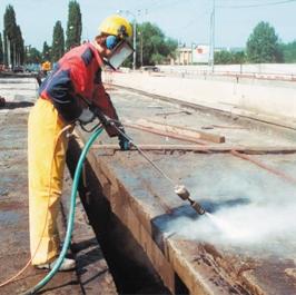


61
 podzemných objektov")


62 podzemných komunika ných objektov (cestné a železni né tunely, privádza e) priestorov podzemných objektov (garáže, zásobníky) podzemných objektov vodohospodárskych stavieb podzemné konštruk né steny prefabrikované/monolitické podzemné pilótové steny konštruk né/tesniace podzemné tesniace steny injektované podzemné steny horninové kotvy lanové/ty ové injektované mikropilóty injektované klince paženie striekaným betónom injek né vrty tesniace clony, spev ovanie podložia odvod ovacie horizontálne vrty malopriemerové pilóty ve kopriemerové pilóty tel.: fax: tunely@vahostav-tsz.sk
Litosil - application
 Litosil - application The series of Litosil is primarily determined for cut polished floors. The cut polished floors are supplied by some specialized firms which are fitted with the appropriate technical
Vánoční sety Christmas sets
 Energy news 7 Inovace Innovations 1 Vánoční sety Christmas sets Na jaře tohoto roku jste byli informováni o připravované akci pro předvánoční období sety Pentagramu koncentrátů a Pentagramu krémů ve speciálních
Tento materiál byl vytvořen v rámci projektu Operačního programu Vzdělávání pro konkurenceschopnost.
 Tento materiál byl vytvořen v rámci projektu Operačního programu Vzdělávání pro konkurenceschopnost. Projekt MŠMT ČR Číslo projektu Název projektu školy Klíčová aktivita III/2 EU PENÍZE ŠKOLÁM CZ.1.07/1.4.00/21.2146
Registration document doc / PDF. Invitation and Congress Program doc
 28.8. - 1.9. 2018 Registration document doc / PDF Invitation and Congress Program doc The Association of Collectors and Friends of Exlibris () as an organiser of the 37th FISAE Congress to be held in Prague
PÁSOVÉ PILY NA KOV - BAND SAWS MACHINE - ЛЕНТОЧНЫЕ ПИЛЫ SCIES Á BANDE - BANDSAEGEMASCHINEN - PRZECINARKI TAŚMOWE NA KOV SCIES A RUBAN - SIERRAS DE
 PÁSOVÉ PILY NA KOV - BAND SAWS MACHINE - ЛЕНТОЧНЫЕ ПИЛЫ SCIES Á BANDE - BANDSAEGEMASCHINEN - PRZECINARKI TAŚMOWE NA KOV SCIES A RUBAN - SIERRAS DE CINTA - SEGATRICI EXPORT TO THE WHOLE WORLD / EXPORT
Contact person: Stanislav Bujnovský,
 Tender documentation link: https://nen.nipez.cz/seznamzadavacichpostupu/zakladniinformaceozadavacimpostupum- 674611632-20523816/ZakladniInformaceOZadavacimPostupu-674611632-20523816/ Contact person: Stanislav
Čtvrtý Pentagram The fourth Pentagram
 Energy News 4 1 Čtvrtý Pentagram The fourth Pentagram Na jaře příštího roku nabídneme našim zákazníkům již čtvrtý Pentagram a to Pentagram šamponů. K zavedení tohoto Pentagramu jsme se rozhodli na základě
/ 1. I nadále budeme vyhledávat možnosti uplatnění na zahraničních aktivitách, kde jsme v předešlých letech načerpali dostatek zkušeností
 Za zmínku rovněž stojí naše schopnost realizace staveb zadávaných formou projektu i stavby samotné. V hierarchii železničních stavebních firem se nám v roce 201 S v několika případech podařilo- {formou
CZECH BUSINESS CLUB IN THE UAE 18 TH AUGUST 2014, PRAGUE
 CZECH BUSINESS CLUB IN THE UAE 18 TH AUGUST 2014, PRAGUE CZECH BUSINESS CLUB VE SPOJENÝCH ARABSKÝCH EMIRÁTECH 18. SRPNA 2014, PRAHA FOUNDATION OF THE CZECH BUSINESS CLUB Czech business community in the
SUBSTRUCTURES underground structures
 SUBSTRUCTURES underground structures FUNCTION AND REQUIREMENTS Static function substructure transfers the load to the foundation soil: vertical loading from upper stucture horizontal reaction of upper
USER'S MANUAL FAN MOTOR DRIVER FMD-02
 USER'S MANUAL FAN MOTOR DRIVER FMD-02 IMPORTANT NOTE: Read this manual carefully before installing or operating your new air conditioning unit. Make sure to save this manual for future reference. FMD Module
PC/104, PC/104-Plus. 196 ept GmbH I Tel. +49 (0) / I Fax +49 (0) / I I
 / I Fax +49 (0) / I I") E L E C T R O N I C C O N N E C T O R S 196 ept GmbH I Tel. +49 (0) 88 61 / 25 01 0 I Fax +49 (0) 88 61 / 55 07 I E-Mail sales@ept.de I www.ept.de Contents Introduction 198 Overview 199 The Standard 200
E L E C T R O N I C C O N N E C T O R S 196 ept GmbH I Tel. +49 (0) 88 61 / 25 01 0 I Fax +49 (0) 88 61 / 55 07 I E-Mail sales@ept.de I www.ept.de Contents Introduction 198 Overview 199 The Standard 200
Project Life-Cycle Data Management
 Project Life-Cycle Data Management 1 Contend UJV Introduction Problem definition Input condition Proposed solution Reference Conclusion 2 UJV introduction Research, design and engineering company 1000
Organizace a řízení tunelových staveb a stavební dozor. Organization and Control of Tunnel Projects and Construction Supervision
 G 3PRAGUE Tunelářské odpoledne 3/313 Organizace a řízení tunelových staveb a stavební dozor Tunnel Seminar Organization and Control of Tunnel Projects and Construction Supervision 2.11.213 Praha, Hotel
Číslo projektu: CZ.1.07/1.5.00/ Název projektu: Inovace a individualizace výuky
 Číslo projektu: CZ.1.07/1.5.00/34.0036 Název projektu: Inovace a individualizace výuky Autor: Mgr. Libuše Matulová Název materiálu: European Union Označení materiálu: VY_32_INOVACE_MAT 22 Datum vytvoření:
VY_32_INOVACE_06_Předpřítomný čas_03. Škola: Základní škola Slušovice, okres Zlín, příspěvková organizace
 VY_32_INOVACE_06_Předpřítomný čas_03 Autor: Růžena Krupičková Škola: Základní škola Slušovice, okres Zlín, příspěvková organizace Název projektu: Zkvalitnění ICT ve slušovské škole Číslo projektu: CZ.1.07/1.4.00/21.2400
VYSOKÁ ŠKOLA HOTELOVÁ V PRAZE 8, SPOL. S R. O.
 VYSOKÁ ŠKOLA HOTELOVÁ V PRAZE 8, SPOL. S R. O. Návrh konceptu konkurenceschopného hotelu v době ekonomické krize Diplomová práce 2013 Návrh konceptu konkurenceschopného hotelu v době ekonomické krize Diplomová
Gymnázium, Brno, Slovanské nám. 7 WORKBOOK. Mathematics. Teacher: Student:
 WORKBOOK Subject: Teacher: Student: Mathematics.... School year:../ Conic section The conic sections are the nondegenerate curves generated by the intersections of a plane with one or two nappes of a cone.
Kladenská továrna jak se stavěla
 4000018 2015 Kladenská továrna jak se stavěla 2000 Byla vystavěna první část továrny v průmyslové zóně Kladno jih, tzv. Budova A. V dalších deseti letech docházelo k jejímu postupnému rozšiřování. 2006
GUIDELINES FOR CONNECTION TO FTP SERVER TO TRANSFER PRINTING DATA
 GUIDELINES FOR CONNECTION TO FTP SERVER TO TRANSFER PRINTING DATA What is an FTP client and how to use it? FTP (File transport protocol) - A protocol used to transfer your printing data files to the MAFRAPRINT
Petr Bednář managing director
 PRESENTATION Petr Bednář managing director Company profile Designing office Petr Bednář Tebeco was established in 2004. At the beginning the company was mainly focusing on mechanical-engineering consulting
HOTEL ZLI!ÍN A NEW PROJECT FOR SALE IN PRAGUE 5 ZLI!ÍN, CZECH REPUBLIC. ARCHITECT: ALFAVILLE, spol. s r.o. Ing.arch. Marek Todl www.alfaville.
 HOTEL ZLI!ÍN A NEW PROJECT FOR SALE IN PRAGUE 5 ZLI!ÍN, CZECH REPUBLIC ARCHITECT: ALFAVILLE, spol. s r.o. Ing.arch. Marek Todl www.alfaville.cz Project of a new hotel with restaurant in Prague - Zlicin.
Mechanika Teplice, výrobní družstvo, závod Děčín TACHOGRAFY. Číslo Servisní Informace Mechanika: 5-2013
 Mechanika Teplice, výrobní družstvo, závod Děčín TACHOGRAFY Servisní Informace Datum vydání: 20.2.2013 Určeno pro : AMS, registrované subj.pro montáž st.měř. Na základě SI VDO č./datum: Není Mechanika
for your fingerboard and for your fingers
 for your fingerboard and for your fingers big construction for your f ingerboard www.bigconstruction.cz big construction for your f ingerboard Rampy Big Construction jsou jedny z nejlepších ramp pro fingerboarding
Střední průmyslová škola strojnická Olomouc, tř.17. listopadu 49
 Střední průmyslová škola strojnická Olomouc, tř.17. listopadu 49 Výukový materiál zpracovaný v rámci projektu Výuka moderně Registrační číslo projektu: CZ.1.07/1.5.00/34.0205 Šablona: III/2 Anglický jazyk
B1 MORE THAN THE CITY
 B1 MORE THAN THE CITY INTRODUCTION ÚVOD B1 Budova B1 je součástí moderního kancelářského projektu CITY WEST a nově budované městské čtvrti Západní město, Praha 5 - Stodůlky. Tato lokalita kromě vynikající
TECHSTA 2000 ČVUT PRAHA FAKULTA STAVEBNÍ KATEDRA TECHNOLOGIE STAVEB
 ČVUT PRAHA FAKULTA STAVEBNÍ KATEDRA TECHNOLOGIE STAVEB 1 SBORNÍK PŘEDNÁŠEK Z KONFERENCE Vydalo ČVUT Praha, Stavební fakulta, ČR ZÁŘÍ 2000 Tématické oblasti konference Příprava a modelování realizace staveb
EXACT DS OFFICE. The best lens for office work
 EXACT DS The best lens for office work EXACT DS When Your Glasses Are Not Enough Lenses with only a reading area provide clear vision of objects located close up, while progressive lenses only provide
AIC ČESKÁ REPUBLIKA CZECH REPUBLIC
 ČESKÁ REPUBLIKA CZECH REPUBLIC ŘÍZENÍ LETOVÉHO PROVOZU ČR, s.p. Letecká informační služba AIR NAVIGATION SERVICES OF THE C.R. Aeronautical Information Service Navigační 787 252 61 Jeneč A 1/14 20 FEB +420
Vypsání závodu / Notice of Race strana/page 1/5. Compotech Cup. v lodních třídách / in classes. D-One, 7P CTL 161315
 Vypsání závodu / Notice of Race strana/page 1/5 Compotech Cup v lodních třídách / in classes D-One, 7P CTL 161315 Datum / date: 04.06.2016 05.06.2016 místo konání : Kemp Jestřábí 1, Lipno Černá v Pošumaví
1, Žáci dostanou 5 klíčových slov a snaží se na jejich základě odhadnout, o čem bude následující cvičení.
 Moje hlavní město Londýn řešení: 1, Žáci dostanou 5 klíčových slov a snaží se na jejich základě odhadnout, o čem bude následující cvičení. Klíčová slova: capital, double decker bus, the River Thames, driving
AMOSDESIGN CESTA K ÚSPĚCHU THE ROAD TO SUCCESS
 AMOSDESIGN CESTA K ÚSPĚCHU 1 / Moravská galerie Brno UPM expozice 2 / Soukromá rezidence Brno postel / Corian / Mendelova univerzita v Brně velká aula 4 / Soukromá rezidence Brno kuchyňský ostrov / Corian
PART 2 - SPECIAL WHOLESALE OFFER OF PLANTS SPRING 2016 NEWS MAY 2016 SUCCULENT SPECIAL WHOLESALE ASSORTMENT
 PART 2 - SPECIAL WHOLESALE OFFER OF PLANTS SPRING 2016 NEWS MAY 2016 SUCCULENT SPECIAL WHOLESALE ASSORTMENT Dear Friends We will now be able to buy from us succulent plants at very good wholesale price.
GENERAL INFORMATION RUČNÍ POHON MANUAL DRIVE MECHANISM
 KATALOG CATALOGUE RUČNÍ POHONY PRO VENKOVNÍ PŘÍSTROJE, MONTÁŽ NA BETONOVÉ SLOUPY MANUAL DRIVE MECHANISM FOR THE ACTUATION OF OUTDOOR TYPE SWITCHING DEVICES MOUNTED ON THE CONCRETE POLES TYP RPV ISO 9001:2009
Rok realizace: Lokalita: Praha
 Rok realizace: 2003 Lokalita: Praha Popis: Koncepční návrh ocelov ch konstrukcí, všechny stupně projektové dokumentace, autorsk dozor, v robní v kresy, teoretické podklady pro montáž, v roba středového
Vliv metody vyšetřování tvaru brusného kotouče na výslednou přesnost obrobku
 Vliv metody vyšetřování tvaru brusného kotouče na výslednou přesnost obrobku Aneta Milsimerová Fakulta strojní, Západočeská univerzita Plzeň, 306 14 Plzeň. Česká republika. E-mail: anetam@kto.zcu.cz Hlavním
Czech Republic. EDUCAnet. Střední odborná škola Pardubice, s.r.o.
 Czech Republic EDUCAnet Střední odborná škola Pardubice, s.r.o. ACCESS TO MODERN TECHNOLOGIES Do modern technologies influence our behavior? Of course in positive and negative way as well Modern technologies
SANAČNÍ A KOMPENZAČNÍ INJEKTÁŽE NA TUNELU MRÁZOVKA
 Ing. Jan Šperger Zakládání staveb, a. s. SANAČNÍ A KOMPENZAČNÍ INJEKTÁŽE NA TUNELU MRÁZOVKA The grouting at the tunnel Mrázovka There were two grouting methods used at the tunnel Mrázovka. The first of
DATA SHEET. BC516 PNP Darlington transistor. technický list DISCRETE SEMICONDUCTORS Apr 23. Product specification Supersedes data of 1997 Apr 16
 zákaznická linka: 840 50 60 70 DISCRETE SEMICONDUCTORS DATA SHEET book, halfpage M3D186 Supersedes data of 1997 Apr 16 1999 Apr 23 str 1 Dodavatel: GM electronic, spol. s r.o., Křižíkova 77, 186 00 Praha
Energy vstupuje na trh veterinárních produktů Energy enters the market of veterinary products
 Energy news2 1 Energy vstupuje na trh veterinárních produktů Energy enters the market of veterinary products Doposud jste Energy znali jako výrobce a dodavatele humánních přírodních doplňků stravy a kosmetiky.
List of Presentations and Minutes
 Summary BESTUFS II national seminar in the Czech Republic 20 th May 2008 Freight Urban Transport Centrum dopravniho vyzkumu Lisenska 33a Brno List of Presentations and Minutes Invitation Doc. Ing. Karel
Myšák Gallery. Vodičkova 710/31, 110 00 Praha 1
 Vodičkova 710/31, 110 00 Praha 1 POPIS Tato budova nabízí moderní kancelářské prostory a obchodní prostory o celkové rozloze 7.400 m2 splňující mezinárodní standardy. Velký důraz byl kladen na flexibilní
Ministerstvo školství, mládeže a tělovýchovy Karmelitská 7, 118 12 Praha 1 tel.: +420 234 811 111 msmt@msmt.cz www.msmt.cz
 Akreditační systém vysokoškolského vzdělávání v ČR v připravované novele zákona o vysokých školách Higher Education Accreditation System in the Czech Republic in a proposal of an amendment to the Higher
MEDIA RESEARCH RATINGS
 READERS OF MF DNES MEDIA RESEARCH RATINGS National media ratings research in the Czech Republic jointly requested by the publishers of dailies and magazines associated in the Publisher s Union (Unie vydavatelů)
ČESKÁ FOTOGRAFIE CZECH PHOTOGRAPHY 2008. p r o S P O R T B E Z B A R I É R. Roman Šebrle
 p r o S P O R T B E Z B A R I É R f o r S p o r t w i t h o u t B a r r i e r s Foto/Photo: HERBERT SLAVÍK Roman Šebrle Prodejem kalendáře, vydaného ve spolupráci s Českým olympijským výborem, získává
Research infrastructure in the rhythm of BLUES. More time and money for entrepreneurs
 Research infrastructure in the rhythm of BLUES More time and money for entrepreneurs 1 I. What is it? II. How does it work? III. References Where to find out more? IV. What is it good for? 2 I. What is
ITICA. SAP Školení přehled 2012. Seznam kurzů
 ITICA SAP Školení přehled 2012 Seznam kurzů SAP Školení v roce 2012 Způsob realizace školení Naše školení jsou zaměřena především na cíl předvést obrovský a rozsáhlý systém SAP jako použitelný a srozumitelný
By plane to Brno International Brno Tuřany Airport. Direct connections to London/Stansted (UK), Munich (Germany) and Prague (Czech Republic).
, Munich (Germany) and Prague (Czech Republic).") TRAVEL INFORMATION Informations about Brno are on web pages : http://www.brnocard.com/en/ By plane to Brno International Brno Tuřany Airport. Direct connections to London/Stansted (UK), Munich (Germany)
TRAVEL INFORMATION Informations about Brno are on web pages : http://www.brnocard.com/en/ By plane to Brno International Brno Tuřany Airport. Direct connections to London/Stansted (UK), Munich (Germany)
STORAGE, TRANSPORTATION, HANDLING MANUAL D0141.STHM.01
 STORAGE, TRANSPORTATION, HANDLING MANUAL GENERÁTOROVÉ ROZVÁDĚCÍ SKŘÍNĚ VN - PRIMÁRNÍ ROZVOD, VNITŘNÍ / VENKOVNÍ PROVEDENÍ GENERATOR MV SWITCHGEAR PRIMARY DISTRIBUTION, INDOOR / OUTDOOR DESIGN ISO 9001:2009
MEDIA RESEARCH RATINGS
 READERS OF MF DNES MEDIA RESEARCH RATINGS National media ratings research in the Czech Republic jointly requested by the publishers of dailies and magazines associated in the Publisher s Union (Unie vydavatelů)
Just write down your most recent and important education. Remember that sometimes less is more some people may be considered overqualified.
 CURRICULUM VITAE - EDUCATION Jindřich Bláha Výukový materiál zpracován v rámci projektu EU peníze školám Autorem materiálu a všech jeho částí, není-li uvedeno jinak, je Bc. Jindřich Bláha. Dostupné z Metodického
Britské společenství národů. Historie Spojeného království Velké Británie a Severního Irska ročník gymnázia (vyšší stupeň)
") Název vzdělávacího materiálu: Číslo vzdělávacího materiálu: Autor vzdělávací materiálu: Období, ve kterém byl vzdělávací materiál vytvořen: Vzdělávací oblast: Vzdělávací obor: Vzdělávací předmět: Tematická
Název vzdělávacího materiálu: Číslo vzdělávacího materiálu: Autor vzdělávací materiálu: Období, ve kterém byl vzdělávací materiál vytvořen: Vzdělávací oblast: Vzdělávací obor: Vzdělávací předmět: Tematická
Tabulka 1 Stav členské základny SK Praga Vysočany k roku 2015 Tabulka 2 Výše členských příspěvků v SK Praga Vysočany Tabulka 3 Přehled finanční
 Příloha I Seznam tabulek Tabulka 1 Stav členské základny SK Praga Vysočany k roku 2015 Tabulka 2 Výše členských příspěvků v SK Praga Vysočany Tabulka 3 Přehled finanční odměny pro rozhodčí platný od roku
The tension belt serves as a tension unit. After emptying the belt is cleaned with a scraper.
 Second School Year BELT AND WORM CONVEYORS They are machines for transporting piece or loose materials even for great distances. In loaders and unloaders it is not necessary to stop the conveyor. The transport
Fytomineral. Inovace Innovations. Energy News 04/2008
 Energy News 4 Inovace Innovations 1 Fytomineral Tímto Vám sdělujeme, že již byly vybrány a objednány nové lahve a uzávěry na produkt Fytomineral, které by měly předejít únikům tekutiny při přepravě. První
MEDIA RESEARCH RATINGS
 READERS OF MF DNES MEDIA RESEARCH RATINGS National media ratings research in the Czech Republic jointly requested by the publishers of dailies and magazines associated in the Publisher s Union (Unie vydavatelů)
Tento materiál byl vytvořen v rámci projektu Operačního programu Vzdělávání pro konkurenceschopnost.
 Tento materiál byl vytvořen v rámci projektu Operačního programu Vzdělávání pro konkurenceschopnost. Projekt MŠMT ČR Číslo projektu Název projektu školy Klíčová aktivita III/2 EU PENÍZE ŠKOLÁM CZ.1.07/1.4.00/21.2146
Moloko ateliér s.r.o. Moloko ateliér s.r.o.
 Moloko ateliér s.r.o. Ateliér pro komunikaci a reklamu SPECIALIZACE firemní časopisy PŘEDSTAVENÍ Na reklamním trhu působíme od roku 1995, nejprve jako agentura Monte Cristo s.r.o, kterou spolumajitelé
Příručka ke směrnici 89/106/EHS o stavebních výrobcích / Příloha III - Rozhodnutí Komise
 Příručka ke směrnici 89/106/EHS o stavebních výrobcích / Příloha III - Rozhodnutí Komise ROZHODNUTÍ KOMISE ze dne 27. června 1997 o postupu prokazování shody stavebních výrobků ve smyslu čl. 20 odst. 2
Název projektu: Multimédia na Ukrajinské
 Základní škola, Ostrava Poruba, Ukrajinská 1533, příspěvková organizace Operační program Vzdělávání pro konkurenceschopnost Název projektu: Multimédia na Ukrajinské číslo projektu: CZ1.07/1.4.00/21.3759
Energy Saving Fund City of Litoměřice. Riga 25 th September 2015
 Energy Saving Fund City of Litoměřice Riga 25 th September 2015 Overview Introduction - City of Litoměřice Main activities in the energy sector Support of solar system for citizens Reasons for ESF establishment
2N Voice Alarm Station
 2N Voice Alarm Station 2N Lift1 Installation Manual Version 1.0.0 www.2n.cz EN Voice Alarm Station Description The 2N Voice Alarm Station extends the 2N Lift1/ 2N SingleTalk with an audio unit installed
Příručka ke směrnici 89/106/EHS o stavebních výrobcích / Příloha III - Rozhodnutí Komise
 Příručka ke směrnici 89/106/EHS o stavebních výrobcích / Příloha III - Rozhodnutí Komise ROZHODNUTÍ KOMISE ze dne 17. února 1997 o postupu prokazování shody stavebních výrobků ve smyslu čl. 20 odst. 2
Theme 6. Money Grammar: word order; questions
 Theme 6 Money Grammar: word order; questions Čas potřebný k prostudování učiva lekce: 8 vyučujících hodin Čas potřebný k ověření učiva lekce: 45 minut KLÍNSKÝ P., MÜNCH O., CHROMÁ D., Ekonomika, EDUKO
EEA and Norway Grants. Norské fondy a fondy EHP
 EEA Scholarship Programme & Bilateral Scholarship Programme The programme offers various options for scholarship funding of international institutional cooperation projects and mobilities among the Czech
ActiPack rozšířil výrobu i své prostory EMBAX 2016. Od ledna 2015 jsme vyrobili přes 59.000.000 lahviček či kelímků. Děkujeme za Vaši důvěru!
 ACTIPACK CZ, a.s. www.actipack.cz Newsletter 2/2015 ActiPack rozšířil výrobu i své prostory Vážení obchodní partneři, Závod prošel významnými audity od předních letošní rok byl ve znamení potravinářských
místo, kde se rodí nápady
 místo, kde se rodí nápady a private european network of information centres on materials and innovative products. Created in 2001 in Paris, it provides members with a large selection of specific, reproducible
READERS OF MAGAZÍN DNES + TV
 READERS OF MAGAZÍN + MEDIA RESEARCH RATINGS National media ratings research in the Czech Republic jointly requested by the publishers of dailies and magazines associated in the Publisher s Union (Unie
Drags imun. Innovations
 Energy news 2 Inovace Innovations 1 Drags imun V příštích plánovaných výrobních šaržích dojde ke změně balení a designu tohoto produktu. Designové změny sledují úspěšný trend započatý novou generací Pentagramu
4Ever H A N D B O O K
 4Ever HANDBOOK Kancelářský systém 4Ever Úvod Základními stavebními komponenty podnoží jsou bočnice a podélné nosníky. Bočnice je tvořena nohami čtvercového průřezu 45 x 45 mm, spojovacím vodorovným bočním
USING VIDEO IN PRE-SET AND IN-SET TEACHER TRAINING
 USING VIDEO IN PRE-SET AND IN-SET TEACHER TRAINING Eva Minaříková Institute for Research in School Education, Faculty of Education, Masaryk University Structure of the presentation What can we as teachers
Moderní technologie dokončování velmi přesných děr vystržováním a její vliv na užitné vlastnosti výrobků
 Moderní technologie dokončování velmi přesných děr vystržováním a její vliv na užitné vlastnosti výrobků Stanislav Fiala 1, Ing. Karel Kouřil, Ph.D 1, Jan Řehoř 2. 1 HAM-FINAL s.r.o, Vlárská 22, 628 00
Risk management in the rhythm of BLUES. Více času a peněz pro podnikatele
 Risk management in the rhythm of BLUES Více času a peněz pro podnikatele 1 I. What is it? II. How does it work? III. How to find out more? IV. What is it good for? 2 I. What is it? BLUES Brain Logistics
GENERAL INFORMATION MATCH: ALSA PRO ARENA MASTERS DATE: TIME SCHEDULE:
 GENERAL INFORMATION MATCH: ALSA PRO ARENA MASTERS DATE: 22.9. - 23.9.2018 TIME SCHEDULE: Mainmatch 1 - Saturday 22.9. registration: 22.9.2018-9.00h first shot: 22.9.2018-10.00h Mainmatch 2 - Sunday 23.9.
These connections are divided into: a) with a form-contact b) with a force-contact
 with a form-contact b) with a force-contact") First School Year SHAFT CONNECTIONS WITH HUBS We can see shaft connections with hubs as shaft connections with a disk of couplings, a belt or a gear wheal. The hub can be solidly fixed or movable. The
First School Year SHAFT CONNECTIONS WITH HUBS We can see shaft connections with hubs as shaft connections with a disk of couplings, a belt or a gear wheal. The hub can be solidly fixed or movable. The
Zelené potraviny v nových obalech Green foods in a new packaging
 Energy News1 1 Zelené potraviny v nových obalech Green foods in a new packaging Již v minulém roce jsme Vás informovali, že dojde k přebalení všech tří zelených potravin do nových papírových obalů, které
TOP 4 KOMBI READERS OF MAGAZÍN DNES + TV, ONA DNES, DOMA DNES AND PÁTEK LIDOVÉ NOVINY
 READERS OF MAGAZÍN +, ONA, DOMA AND PÁTEK LIDOVÉ NOVINY MEDIA RESEARCH RATINGS National media ratings research in the Czech Republic jointly requested by the publishers of dailies and magazines associated
StandardLine DIMENSIONED SKETCH ROZMĚROVÁ ŘADA
 EN Standard dwelling and sanitary containers are used as temporary constructions. They can be also used for permanent constructions following some modification of containers. Variable options of insulation,
MEDIA RESEARCH RATINGS
 READERS OF MF DNES MEDIA RESEARCH RATINGS National media ratings research in the Czech Republic jointly requested by the publishers of dailies and magazines associated in the Publisher s Union (Unie vydavatelů)
1-AYKY. Instalační kabely s Al jádrem. Standard TP-KK-133/01, PNE 347659-3. Konstrukce. Použití. Vlastnosti. Installation cables with Al conductor
 Instalační kabely s Al jádrem Installation cables with Al conductor Standard TP-KK-133/01, PNE 347659-3 4 3 2 1 Konstrukce Construction 1 Hliníkové jádro Aluminium conductor 2 Izolace PVC 3 Výplňový obal
Informace o písemných přijímacích zkouškách. Doktorské studijní programy Matematika
 Informace o písemných přijímacích zkouškách (úplné zadání zkušebních otázek či příkladů, které jsou součástí přijímací zkoušky nebo její části, a u otázek s výběrem odpovědi správné řešení) Doktorské studijní
Systém fasádní - Konstrukce VF50 a VF50RR. Hueck Hartmann
 Systém fasádní - Konstrukce VF50 a VF50RR. Hueck Hartmann Obě tyto konstrukce jsou klasické hliníkové rastrové fasády s přítlačnými a krycími profily s pohledovou šířkou 50 mm. Tepelná vložka je patentově
TKGA3. Pera a klíny. Projekt "Podpora výuky v cizích jazycích na SPŠT"
 Projekt "Podpora výuky v cizích jazycích na SPŠT" Pera a klíny TKGA3 Tento projekt je spolufinancován Evropským sociálním fondem a státním rozpočtem ČR Pera a klíny Pera a klíny slouží k vytvoření rozbíratelného
READERS OF MAGAZÍN DNES + TV
 READERS OF MAGAZÍN + MEDIA RESEARCH RATINGS National media ratings research in the Czech Republic jointly requested by the publishers of dailies and magazines associated in the Publisher s Union (Unie
MEDIA RESEARCH RATINGS
 READERS OF MF DNES MEDIA RESEARCH RATINGS National media ratings research in the Czech Republic jointly requested by the publishers of dailies and magazines associated in the Publisher s Union (Unie vydavatelů)
Pokyny k použití. Model-300. Napájecí zdroj. Návod na obsluhu Operating Instructions. se systémem Aquacontrol Napájací zdroj
 Pokyny k použití Model-300 Návod na obsluhu Operating Instructions Napájecí zdroj se systémem Napájací zdroj so systémom Power Supply with System BK 0011900 / PC AQUACONTROL Kryt aquacontrol Kryt aquacontrol
CZ.1.07/1.5.00/
 Projekt: Příjemce: Digitální učební materiály ve škole, registrační číslo projektu CZ.1.07/1.5.00/34.0527 Střední zdravotnická škola a Vyšší odborná škola zdravotnická, Husova 3, 371 60 České Budějovice
TKGA6. Pružiny a výkres součásti. Projekt "Podpora výuky v cizích jazycích na SPŠT"
 Projekt "Podpora výuky v cizích jazycích na SPŠT" Pružiny a výkres součásti TKGA6 Tento projekt je spolufinancován Evropským sociálním fondem a státním rozpočtem ČR 1 Pružiny Pružiny jsou strojní součásti
Friction drives have constant or variable drives (it means variators). Friction drives are used for the transfer of smaller outputs.
. Friction drives are used for the transfer of smaller outputs.") Third School Year FRICTION DRIVES 1. Introduction In friction drives the peripheral force between pressed wheels is transferred by friction. To reach peripheral forces we need both a pressed force and
Third School Year FRICTION DRIVES 1. Introduction In friction drives the peripheral force between pressed wheels is transferred by friction. To reach peripheral forces we need both a pressed force and
EURO přeshraniční platba
 EURO přeshraniční platba EURO přeshraniční platba je platební příkaz splňující následující kriteria: Je předložen elektronicky Je požadováno standardní provedení (tj. nikoliv urgentní nebo expresní) Částka
âasopis âeského TUNELÁ SKÉHO KOMITÉTU A SLOVENSKEJ TUNELÁRSKEJ ASOCIÁCIE ITA/AITES PODZEMNÍ STAVBY (V VOJ, V ZKUM, NAVRHOVÁNÍ, REALIZACE)
") 12. ROâNÍK, ã. 1/2003 âasopis âeského TUNELÁ SKÉHO KOMITÉTU A SLOVENSKEJ TUNELÁRSKEJ ASOCIÁCIE ITA/AITES PODZEMNÍ STAVBY (V VOJ, V ZKUM, NAVRHOVÁNÍ, REALIZACE) MAGAZINE OF THE CZECH TUNNELLING COMMITTEE
12. ROâNÍK, ã. 1/2003 âasopis âeského TUNELÁ SKÉHO KOMITÉTU A SLOVENSKEJ TUNELÁRSKEJ ASOCIÁCIE ITA/AITES PODZEMNÍ STAVBY (V VOJ, V ZKUM, NAVRHOVÁNÍ, REALIZACE) MAGAZINE OF THE CZECH TUNNELLING COMMITTEE
Enabling Intelligent Buildings via Smart Sensor Network & Smart Lighting
 Enabling Intelligent Buildings via Smart Sensor Network & Smart Lighting Petr Macháček PETALIT s.r.o. 1 What is Redwood. Sensor Network Motion Detection Space Utilization Real Estate Management 2 Building
READERS OF MAGAZÍN DNES + TV
 READERS OF MAGAZÍN + MEDIA RESEARCH RATINGS National media ratings research in the Czech Republic jointly requested by the publishers of dailies and magazines associated in the Publisher s Union (Unie
UŽIVATELSKÁ PŘÍRUČKA
 UŽIVATELSKÁ PŘÍRUČKA Plni víry a naděje míříme kupředu. S odhodláním zlepšujeme své dovednosti. Zapomeňte na zklamání, ale nikoli na svůj nevyužitý potenciál. Touha překonat sám sebe a dosáhnout hranice
WORKSHEET 1: LINEAR EQUATION 1
 WORKSHEET 1: LINEAR EQUATION 1 1. Write down the arithmetical problem according the dictation: 2. Translate the English words, you can use a dictionary: equations to solve solve inverse operation variable
TECHNICKÝ LIST řada mechanických odvaděčů kondenzátu AUTODRAIN TECHNICAL DATA SHEET for mechanical autodrain equipment AUTODRAIN
 Popis: Nádoba s mechanickým plovákem k odstraňování pevných nečistot, vody, aerosolů, uhlovodíků, prachu oddělených separátory KING AIR se systémem stlačeného vzduchu. Rozdělení dle využití instalace:
Co vím o Ázerbájdžánu?
 Ministerstvo mládeže a sportu Ázerbájdžánské republiky Ministerstvo zahraničních věcí Ázerbájdžánské republiky Velvyslanectví Ázerbájdžánské republiky v Praze ve spolupráci s Centrem ázerbájdžánských a
Návrh a implementace algoritmů pro adaptivní řízení průmyslových robotů
 Návrh a implementace algoritmů pro adaptivní řízení průmyslových robotů Design and implementation of algorithms for adaptive control of stationary robots Marcel Vytečka 1, Karel Zídek 2 Abstrakt Článek
Introduction to MS Dynamics NAV
 Introduction to MS Dynamics NAV (Item Charges) Ing.J.Skorkovský,CSc. MASARYK UNIVERSITY BRNO, Czech Republic Faculty of economics and business administration Department of corporate economy Item Charges
STUDY EDITS FOR BETTER TRANSPORT IN THE CENTRE OF NÁCHOD
 CZECH TECHNICAL UNIVERSITY IN PRAGUE Faculty of transportation sciences Title of project STUDY EDITS FOR BETTER TRANSPORT IN THE CENTRE OF NÁCHOD 2006 Petr Kumpošt Basic information about town Náchod Náchod