INSTALLATION MANUAL. Indoor unit for air to water heat pump system RKHBRD011ADV1 RKHBRD014ADV1 RKHBRD016ADV1 RKHBRD011ADY1 RKHBRD014ADY1 RKHBRD016ADY1
|
|
|
- Kateřina Kubíčková
- před 6 lety
- Počet zobrazení:
Transkript
1 INSTLLTION MNUL RKHBRD0DV RKHBRD04DV RKHBRD06DV RKHBRD0DY RKHBRD04DY RKHBRD06DY


2 x x 4 5 x x 6 x 7 6x 8 x 9 x x 0 x 4 x x x x 0 50 E D PS LV HV HV LV PS C B >50 >50 >500 LV HV HV LV PS PS >600 PS LV HV LV HV+PS Ø
3 CE - TITIKTIES-DEKLRCIJ CE - TBILSTĪBS-DEKLRĀCIJ CE - VYHLÁSENIE-ZHODY CE - UYUMLULUK-BEYNI CE - IZJV O SKLDNOSTI CE - VSTVUSDEKLRTSIOON CE - ДЕКЛАРАЦИЯ-ЗА-СЪОТВЕТСТВИЕ CE - IZJV-O-USKLĐENOSTI CE - MEGFELELŐSÉGI-NYILTKOZT CE - DEKLRCJ-ZGODNOŚCI CE - DECLRŢIE-DE-CONFORMITTE CE - ERKLÆRING OM-SMSVR CE - ILMOITUS-YHDENMUKISUUDEST CE - PROHLÁŠENÍ-O-SHODĚ CE - DECLRÇÃO-DE-CONFORMIDDE СЕ - ЗАЯВЛЕНИЕ-О-СООТВЕТСТВИИ CE - OPFYLDELSESERKLÆRING CE - FÖRSÄKRN-OM-ÖVERENSTÄMMELSE CE - DECLRCION-DE-CONFORMIDD CE - DICHIRZIONE-DI-CONFORMIT CE - H ø H YMMOPºø H CE - DECLRTION-OF-CONFORMITY CE - KONFORMITÄTSERKLÄRUNG CE - DECLRTION-DE-CONFORMITE CE - CONFORMITEITSVERKLRING ROTEX 7 m deklaruje na własną wyłączną odpowiedzialność, że urządzenia, których ta deklaracja dotyczy: 8 r declară pe proprie răspundere că echipamentele la care se referă această declaraţie: 9 o z vso odgovornostjo izjavlja, da je oprema naprav, na katero se izjava nanaša: 0 x kinnitab oma täielikul vastutusel, et käesoleva deklaratsiooni alla kuuluv varustus: b декларира на своя отговорност, че оборудването, за което се отнася тази декларация: t visiška savo atsakomybe skelbia, kad įranga, kuriai taikoma ši deklaracija: v ar pilnu atbildību apliecina, ka tālāk aprakstītās iekārtas, uz kurām attiecas šī deklarācija: 4 k vyhlasuje na vlastnú zodpovednosť, že zariadenie, na ktoré sa vzťahuje toto vyhlásenie: 5 w tamamen kendi sorumluluğunda olmak üzere bu bildirinin ilgili olduğu donanımının aşağıdaki gibi olduğunu beyan eder: 09 u заявляет, исключительно под свою ответственность, что оборудование, к которому относится настоящее заявление: 0 q erklærer som eneansvarlig, at udstyret, som er omfattet af denne erklæring: s deklarerar i egenskap av huvudansvarig, att utrustningen som berörs av denna deklaration innebär att: n erklærer et fullstendig ansvar for at det utstyr som berøres av denne deklarasjon, innebærer at: j ilmoittaa yksinomaan omalla vastuullaan, että tämän ilmoituksen tarkoittamat laitteet: 4 c prohlašuje ve své plné odpovědnosti, že zařízení, k němuž se toto prohlášení vztahuje: 5 y izjavljuje pod isključivo vlastitom odgovornošću da oprema na koju se ova izjava odnosi: 6 h teljes felelőssége tudatában kijelenti, hogy a berendezések, melyekre e nyilatkozat vonatkozik: 0 a declares under its sole responsibility that the equipment to which this declaration relates: 0 d erklärt auf seine alleinige Verantwortung, dass die usrüstung für die diese Erklärung bestimmt ist: 0 f déclare sous sa seule responsabilité que l équipement visé par la présente déclaration: 04 l verklaart hierbij op eigen exclusieve verantwoordelijkheid dat de apparatuur waarop deze verklaring betrekking heeft: 05 e declara bajo su única responsabilidad que el equipo al que hace referencia la declaración: 06 i dichiara sotto la propria responsabilità che gli apparecchi a cui è riferita questa dichiarazione: 07 g ËÏÒÓÂÈ Ì appleôîïâèûùèî ÙË Â ı ÓË fiùè Ô ÂÍÔappleÏÈÛÌfi ÛÙÔÓ ÔappleÔ Ô Ó Ê ÚÂÙ È Ë apple ÚÔ Û ÏˆÛË: 08 p declara sob sua exclusiva responsabilidade que os equipamentos a que esta declaração se refere: RKHBRD0DV, RKHBRD04DV, RKHBRD06DV, RKHBRD0DY, RKHBRD04DY, RKHBRD06DY, 6 megfelelnek az alábbi szabvány(ok)nak vagy egyéb irányadó dokumentum(ok)nak, ha azokat előírás szerint használják: 7 spełniają wymogi następujących norm i innych dokumentów normalizacyjnych, pod warunkiem że używane są zgodnie z naszymi instrukcjami: 8 sunt în conformitate cu următorul (următoarele) standard(e) sau alt(e) document(e) normativ(e), cu condiţia ca acestea să fie utilizate în conformitate cu instrucţiunile noastre 9 skladni z naslednjimi standardi in drugimi normativi, pod pogojem, da se uporabljajo v skladu z našimi navodili: 0 on vastavuses järgmis(t)e standardi(te)ga või teiste normatiivsete dokumentidega, kui neid kasutatakse vastavalt meie juhenditele: съответстват на следните стандарти или други нормативни документи, при условие, че се използват съгласно нашите инструкции: atitinka žemiau nurodytus standartus ir (arba) kitus norminius dokumentus su sąlyga, kad yra naudojami pagal mūsų nurodymus: tad, ja lietoti atbilstoši ražotāja norādījumiem, atbilst sekojošiem standartiem un citiem normatīviem dokumentiem: 4 sú v zhode s nasledovnou(ými) normou(ami) alebo iným(i) normatívnym(i) dokumentom(ami), za predpokladu, že sa používajú v súlade s našim návodom: 5 ürünün, talimatlarımıza göre kullanılması koşuluyla aşağıdaki standartlar ve norm belirten belgelerle uyumludur: 08 estão em conformidade com a(s) seguinte(s) norma(s) ou outro(s) documento(s) normativo(s), desde que estes sejam utilizados de acordo com as nossas instruções: 09 соответствуют следующим стандартам или другим нормативным документам, при условии их использования согласно нашим инструкциям: 0 overholder følgende standard(er) eller andet/andre retningsgivende dokument(er), forudsat at disse anvendes i henhold til vore instrukser: respektive utrustning är utförd i överensstämmelse med och följer följande standard(er) eller andra normgivande dokument, under förutsättning att användning sker i överensstämmelse med våra instruktioner: respektive utstyr er i overensstemmelse med følgende standard(er) eller andre normgivende dokument(er), under forutssetning av at disse brukes i henhold til våre instrukser: vastaavat seuraavien standardien ja muiden ohjeellisten dokumenttien vaatimuksia edellyttäen, että niitä käytetään ohjeidemme mukaisesti: 4 za předpokladu, že jsou využívány v souladu s našimi pokyny, odpovídají následujícím normám nebo normativním dokumentům: 5 u skladu sa slijedećim standardom(ima) ili drugim normativnim dokumentom(ima), uz uvjet da se oni koriste u skladu s našim uputama: 0 are in conformity with the following standard(s) or other normative document(s), provided that these are used in accordance with our instructions: 0 der/den folgenden Norm(en) oder einem anderen Normdokument oder -dokumenten entspricht/entsprechen, unter der Voraussetzung, daß sie gemäß unseren nweisungen eingesetzt werden: 0 sont conformes à la/aux norme(s) ou autre(s) document(s) normatif(s), pour autant qu'ils soient utilisés conformément à nos instructions: 04 conform de volgende norm(en) of één of meer andere bindende documenten zijn, op voorwaarde dat ze worden gebruikt overeenkomstig onze instructies: 05 están en conformidad con la(s) siguiente(s) norma(s) u otro(s) documento(s) normativo(s), siempre que sean utilizados de acuerdo con nuestras instrucciones: 06 sono conformi al(i) seguente(i) standard(s) o altro(i) documento(i) a carattere normativo, a patto che vengano usati in conformità alle nostre istruzioni: 07 Â Ó È Û ÌÊˆÓ Ì ÙÔ( ) ÎfiÏÔ ıô( ) appleúfiù appleô( ) ÏÏÔ ÁÁÚ ÊÔ( ) Î ÓÔÓÈÛÌÒÓ, applefi ÙËÓ appleúô applefiıâûë fiùè ÚËÛÈÌÔappleÔÈÔ ÓÙ È Û ÌÊˆÓ Ì ÙÈ Ô ËÁ Â Ì : EN , 9 Direktive z vsemi spremembami. 0 Direktiivid koos muudatustega. Директиви, с техните изменения. Direktyvose su papildymais. Direktīvās un to papildinājumos. 4 Smernice, v platnom znení. 5 Değiştirilmiş halleriyle Yönetmelikler. 0 Direktiver, med senere ændringer. Direktiv, med företagna ändringar. Direktiver, med foretatte endringer. Direktiivejä, sellaisina kuin ne ovat muutettuina. 4 v platném znění. 5 Smjernice, kako je izmijenjeno. 6 irányelv(ek) és módosításaik rendelkezéseit. 7 z późniejszymi poprawkami. 8 Directivelor, cu amendamentele respective. 0 Directives, as amended. 0 Direktiven, gemäß Änderung. 0 Directives, telles que modifiées. 04 Richtlijnen, zoals geamendeerd. 05 Directivas, según lo enmendado. 06 Direttive, come da modifica. 07 ËÁÈÒv, fiappleˆ Ô Ó ÙÚÔappleÔappleÔÈËıÂ. 08 Directivas, conforme alteração em. 09 Директив со всеми поправками. Low Voltage 006/95/EC Electromagnetic Compatibility 004/08/EC * 9 ob upoštevanju določb: 0 vastavalt nõuetele: следвайки клаузите на: laikantis nuostatų, pateikiamų: ievērojot prasības, kas noteiktas: 4 održiavajúc ustanovenia: 5 bunun koşullarına uygun olarak: 0 under iagttagelse af bestemmelserne i: enligt villkoren i: gitt i henhold til bestemmelsene i: noudattaen määräyksiä: 4 za dodržení ustanovení předpisu: 5 prema odredbama: 6 követi a(z): 7 zgodnie z postanowieniami Dyrektyw: 8 în urma prevederilor: 0 following the provisions of: 0 gemäß den Vorschriften der: 0 conformément aux stipulations des: 04 overeenkomstig de bepalingen van: 05 siguiendo las disposiciones de: 06 secondo le prescrizioni per: 07 Ì ٠ÚËÛË Ùˆv È Ù Íˆv Ùˆv: 08 de acordo com o previsto em: 09 в соответствии с положениями: Забележка * както е изложено в <> и оценено положително от <B> съгласно Cертификата <C>. Pastaba * kaip nustatyta <> ir kaip teigiamai nuspręsta <B> pagal Sertifikatą <C>. kā norādīts <> un atbilstoši <B> pozitīvajam Piezīmes * vērtējumam saskaņā ar sertifikātu <C>. <> TCF.05H7/0-05 <B> DEKR (NB044) <C> QU/EMC 4 Poznámka * ako bolo uvedené v <> a pozitívne zistené <B> v súlade s osvedčením <C>. 6 Megjegyzés * a(z) <> alapján, a(z) <B> igazolta a megfelelést, a(z) <C> tanúsítvány szerint. 7 Uwaga * zgodnie z dokumentacją <>, pozytywną opinią <B> i Świadectwem <C>. 8 Notă * aşa cum este stabilit în <> şi apreciat pozitiv de <B> în conformitate cu Certificatul <C>. 9 Opomba * kot je določeno v <> in odobreno s strani <B> v skladu s certifikatom <C>. 0 Märkus * nagu on näidatud dokumendis <> ja heaks kiidetud <B> järgi vastavalt sertifikaadile <C>. Information * enligt <> och godkänts av <B> enligt Certifikatet <C>. Merk * som det fremkommer i <> og gjennom positiv bedømmelse av <B> ifølge Sertifikat <C>. Huom * jotka on esitetty asiakirjassa <> ja jotka <B> on hyväksynyt Sertifikaatin <C> mukaisesti. 4 Poznámka * jak bylo uvedeno v <> a pozitivně zjištěno <B> v souladu s osvědčením <C>. 5 Napomena * kako je izloženo u <> i pozitivno ocijenjeno od strane <B> prema Certifikatu <C>. 5 Not * <> da belirtildiği gibi ve <C> Sertifikasına göre <B> tarafından olumlu olarak değerlendirildiği gibi. 06 Nota * delineato nel <> e giudicato positivamente da <B> secondo il Certificato <C>. 07 ËÌ ˆÛË * fiappleˆ Î ıôú ÂÙ È ÛÙÔ <> Î È ÎÚ ÓÂÙ È ıâùèî applefi ÙÔ <B> Û ÌÊˆÓ Ì ÙÔ ÈÛÙÔappleÔÈËÙÈÎfi <C>. 08 Nota * tal como estabelecido em <> e com o parecer positivo de <B> de acordo com o Certificado <C>. 09 Примечание * как указано в <> и в соответствии с положительным решением <B> согласно Свидетельству <C>. 0 Bemærk * som anført i <> og positivt vurderet af <B> i henhold til Certifikat <C>. 0 Note * as set out in <> and judged positively by <B> according to the Certificate <C>. 0 Hinweis * wie in der <> aufgeführt und von <B> positiv beurteilt gemäß Zertifikat <C>. 0 Remarque * tel que défini dans <> et évalué positivement par <B> conformément au Certificat <C>. 04 Bemerk * zoals vermeld in <> en positief beoordeeld door <B> overeenkomstig Certificaat <C>. 05 Nota * como se establece en <> y es valorado positivamente por <B> de acuerdo con el Certificado <C>. Georg Blümel Managing Director st of June 05 P4054-
4 RKHBRD0DV RKHBRD04DV RKHBRD06DV RKHBRD0DY RKHBRD04DY RKHBRD06DY CONTENTS Page Introduction... General information... Scope of this manual... Model identification... Typical application examples... pplication examples with only heat emitter and heat source (RKHBRD unit)... pplication examples with or more different heat emitters and heat source (RKHBRD unit)... 4 pplication examples with different heat sources (auxiliary boiler + RKHBRD unit)... 5 Design of the hydraulic system... 6 ccessories... 7 ccessories supplied with this unit... 7 Overview of the indoor unit... 7 Main components... 7 Switch box main components... 8 Functional diagram... 8 Installation of the indoor unit... 9 Selecting an installation location... 9 Dimensions and service space... 9 Inspecting and handling the unit... 9 Installing the indoor unit... 9 Piping connection work... Refrigerant piping work... Guidelines for flare connection... Water piping work... Checking the water circuit... Checking the water volume and expansion vessel pre-pressure... Setting the pre-pressure of the expansion vessel... 4 Connecting the water circuit... 4 Precautions when connecting field piping and regarding insulation... 4 Charging water... 4 Method for adding water... 4 Electrical wiring work... 5 Precautions on electrical wiring work... 5 Internal wiring - Parts table... 5 System overview of field wiring... 6 Connection of the indoor unit power supply and communication cable(s)... 6 Installation of the remote controller... 7 Connection to a benefit kwh rate power supply... 7 Start-up and configuration... 9 Pre-operation checks... 9 Field settings... 9 Procedure... 0 Detailed description... 0 Simultaneous demand of space heating and domestic water heating... 6 Multiple set point control... 9 Field settings table... Final check and test run... 4 Final check... 4 Test run... 4 Temperature read-out mode... 4 Procedure for space heating... 4 Procedure for domestic water heating... 4 Maintenance and service... 5 Maintenance activities... 5 Troubleshooting... 5 General guidelines... 5 Opening the unit... 6 General symptoms... 6 Error codes... 7 Unit specifications... 8 Technical specifications... 8 Electrical specifications... 8 nnex... 9 RED THESE INSTRUCTIONS CREFULLY BEFORE INSTLLTION. KEEP THIS MNUL IN HNDY PLCE FOR FUTURE REFERENCE. IMPROPER INSTLLTION OR TTCHMENT OF EQUIPMENT OR CCESSORIES COULD RESULT IN ELECTRIC SHOCK, SHORT-CIRCUIT, LEKS, FIRE OR OTHER DMGE TO THE EQUIPMENT. BE SURE ONLY TO USE CCESSORIES, OPTIONL EQUIPMENT, ND SPRE PRTS MDE BY ROTEX WHICH RE SPECIFICLLY DESIGNED FOR USE WITH THE EQUIPMENT ND HVE THEM INSTLLED BY PROFESSIONL. LL CTIVITIES DESCRIBED IN THIS MNUL SHLL BE CRRIED OUT BY LICENSED TECHNICIN. BE SURE TO WER DEQUTE PERSONEL PROTEC- TION EQUIPMENT (PROTECTION GLOVES, SFETY GLSSES,...) WHEN PERFORMING INSTLLTION, MINTENNCE OR SERVICE TO THE UNIT. IF UNSURE OF INSTLLTION PROCEDURES OR USE, LWYS CONTCT YOUR ROTEX DELER FOR DVICE ND INFORMTION. THE UNIT DESCRIBED IN THIS MNUL IS DESIGNED FOR INDOOR INSTLLTION ONLY ND FOR MBIENT TEMPERTURES RNGING 5 C~0 C. The English text is the original instruction. Other languages are translations of the original instructions. INTRODUCTION General information Thank you for purchasing this unit. The unit is the indoor part of the air to water RRRQ heat pump. The unit is designed for floor standing indoor installation and used for heating applications. The unit can be combined with space heating radiators (field supply) and with an RKHTS domestic hot water tank (option). remote controller with room thermostat functionality is standard supplied with this unit to control your installation. n RKHBRD indoor unit can only be connected to an RRRQ outdoor unit. Domestic hot water tank (option) n optional RKHTS domestic hot water tank can be connected to the indoor unit. The domestic hot water tank is available in two different water capacities: 00 and 60 litre. Refer to the domestic hot water tank installation manual for further details. RKHBRD0~06DV+Y 4P
5 Remote controller (option) n optional secondary RKRUHT remote controller (with room thermostat functionality) can be connected to the indoor unit. Purpose is to provide the possibility to install the standard remote controller near the unit (for service reasons), and install another remote controller in another place (e.g. living room) to operate your installation. Refer to the "Installation of the remote controller" on page 7 for further details. Room thermostat (option) n optional room thermostat RKRTR or RKRTW can be connected to the indoor unit. Refer to the room thermostat installation manual for further details. If this option is installed it is not possible to use the remote controller thermostat function. Heater kit (option) n optional RKBUH heater kit can be combined with the indoor unit. Purpose is to provide an additional heating capacity during cold outdoor temperatures. The heater kit has a heating capacity of 6 kw, and available for both -phase and -phase power supply specifications. When using this heater kit, installation of the optional demand PCB is required as well. Refer to the heater kit installation manual for further details. P H Scope of this manual This installation manual describes the procedures for handling, installing and connecting all RKHBRD indoor unit models. Model identification Indoor unit Installation of the RRRQ heat pump outdoor is described in the outdoor unit installation manual. Operation of the indoor unit is described in the indoor unit operation manual. RK HBR D 06 D V V = N~, 0-40 V, 50 Hz Y = N~, V, 50 Hz Series Indication of heating capacity (kw) (a) Refrigerant type R4a Hydro box - high temperature heating only Rotex kit (a) For exact values, refer to "Unit specifications" on page 8. Typical application examples The application examples given below are for illustration purposes only. pplication examples with only heat emitter and heat source (RKHBRD unit) T Heat pump capacity Required heating capacity (site dependent) dditional heating capacity provided by the heater kit T mbient (outdoor) temperature P H Heating capacity If only heat emitter (= all system has water set point), it is recommended NOT to use a balancing bottle. Using a balancing bottle will affect the optimal pump control of the unit and will increase the cost of the system unnecessarily. pplication Space heating and domestic hot water heating with a single remote controller installed in the living room B C Digital I/O PCB (option) n optional EKRPHB digital I/O PCB can be connected to the indoor unit and be used to remotely monitor your system. This address card offers voltage free outputs. Refer to the operation manual of the indoor unit and to the digital I/O PCB installation manual for more information. Refer to the wiring diagram or connection diagram for connecting this PCB to the unit. Demand PCB (option) n optional EKRPHT demand PCB can be connected to the indoor unit. This PCB is needed when the optional heater kit RKBUH or Rotex room thermostat RKRTR or RKRTW is installed or when multiple set point control is used, and provides the communication with the indoor unit. Refer to the demand PCB installation manual for further details. Refer to the wiring diagram or connection diagram for connecting this PCB to the unit. 5 8 M Outdoor unit 9 Domestic hot water Indoor unit tank (optional) Refrigerant heat 0 Collector (field supply) exchanger Radiator (field supply) 4 Water heat exchanger Electronic expansion 5 Compressor valve 6 Pump By-pass valve (field 7 Shut-off valve supply) 8 Motorized -way valve C Remote controller (optional) Installation place B Living room 9 RKHBRD0~06DV+Y 4P
6 The remote controller gives immediate feedback to the indoor unit and by doing so it matches in a smart way the unit performance to the demanded space heating requirements. In this way there is no frequent start/stop of the unit or there are no too big temperature fluctuations in the to be heated rooms. This remote controller has also a smart logic functionality which controls the combined space heating and domestic hot water demand (e.g. if room temperature drops more than C during domestic hot water operation, the unit will automatically switch back to space heating). There is no remote controller near the unit. During service maintenance an additional remote controller can be connected by a service person. pplication Space heating and domestic hot water heating with one remote controller installed with the unit, and another remote controller installed in the living room. C Outdoor unit 0 Collector (field supply) Indoor unit Radiator (field supply) Refrigerant heat exchanger Electronic expansion valve 4 Water heat exchanger By-pass valve (field 5 Compressor supply) 6 Pump C Remote controller 7 Shut-off valve (master) 8 Motorized -way valve (optional) 9 Domestic hot water tank (optional) M 6 The remote controller gives immediate feedback to the indoor unit and by doing so it matches in a smart way the unit performance to the demanded space heating requirements. In this way there is no frequent start/stop of the unit or there are no too big temperature fluctuations in the to be heated rooms. This remote controller has also a smart logic functionality which controls the combined space heating and domestic hot water demand (e.g. if room temperature drops more than C during domestic hot water operation, the unit will automatically switch back to space heating). The main remote controller (C) is installed in the living room and can access all settings (master). The second remote controller (C) can not access schedule and field settings (slave). C B 7 0 Optional remote controller (slave) Installation place Living room B C 9 Master Slave Operation ON/OFF Operable Operable Domestic water heating operation ON/OFF Operable Operable Setting the leaving water temperature Operable Operable Setting the room temperature Operable Operable Quiet mode ON/OFF Operable Operable Weather dependent set point operation Operable Operable ON/OFF Setting the clock Operable Operable Programming the schedule timer Operable Schedule timer operation ON/OFF Operable Field settings Operable Error code display Operable Operable Test operation Operable Operable Room thermostat functionality Operable Refer to the chapter "Electrical wiring work" on page 5 about connecting the master and slave remote controller. pplication Space heating and domestic hot water heating with a single remote controller installed with the unit, and the external room thermostat installed in the living room. Optionally the Rotex room thermostat RKRTR or RKRTW can be connected to the Rotex system. Rotex can not guarantee neither good operation nor reliability of the system if another thermostat is used. For those reasons Rotex can not give warranty of the system in such case. C 5 Outdoor unit 0 Collector (field supply) Indoor unit Radiator (field supply) Refrigerant heat exchanger 4 8 M B T Electronic expansion valve 4 Water heat exchanger By-pass valve (field 5 Compressor supply) 6 Pump C Remote controller 7 Shut-off valve T Room thermostat 8 Motorized -way valve Installation place (optional) B Living room 9 Domestic hot water tank (optional) 9 There is only a room thermostat on/off control. There is no smart logic functionality for space heating. When there is simultaneous demand of space heating and domestic hot water, the domestic hot water operation is performed according to the minimum and maximum timer operation. RKHBRD0~06DV+Y 4P
7 pplication examples with or more different heat emitters and heat source (RKHBRD unit) Using different heat emitters means using different water set points for the system. Such installations must be done using a balancing bottle and each kind of heat emitter should have a specific pump. pplication 4 Space heating provided through a combination of floor heating loops, fan coil unit and radiator heating. For floor heating applications in combination with radiators the water temperature delivered by the Rotex system is too high. For this reason a temperature reducing device (field supply) is required to lower the water temperature (the hot water will be mixed with cold water to lower the temperature). The control of this field supplied valve is not done by the heat pump system. The operation and configuration of the field water circuit and selection of the balancing bottle, the pumps, etc..., are the responsibility of the installer. Rotex only offers the possibility to have multiple set points on request. Pattern The domestic hot water tank is installed in parallel with the temperature reducing device(s). This allows operating the unit in space heating and domestic water heating simultaneously. The balancing of the water distribution is in this case the responsibility of the installer. Shut off valve (field supply) or EKVKHPC -way valve kit for heat pump convector (optional) Pattern B The domestic hot water tank is installed in a separate circuit (with a -way valve) of the temperature reducing device(s). This configuration does not allow simultaneous domestic hot water and space heating operation. C C TRD TRD M 0 0 Remote controller Temperature reducing device Temperature reducing device C FHL 5 C 45 C FCU 65 C TRD TRD FHL 5 C TRD Outdoor unit 4 By-pass valve Indoor unit (field supply) Electronic expansion valve 4 Refrigerant heat exchanger 5 FCU: Fan coil unit or FWXV (optional) 6 Shut-off valve (field supply) 5 Water heat exchanger 7 Radiator (field supply) 6 Pump 8 Mixing valve 8 Domestic hot water (field supply) tank (optional) 9 Pump (field supply) 9 Compressor 0 Non-return valve 0 Shut-off valve (field supply) Balancing bottle (field supply) FHL: Floor heating loop (field supply) 45 C FCU 65 C TRD Valve (field supply) (refer to "Multiple set point control" on page 9 for more details) Outdoor unit Shut off valve (field Indoor unit supply) or EKVKHPC -way valve kit for heat Electronic expansion valve pump convector (optional) 4 Refrigerant heat exchanger 5 Water heat exchanger 4 By-pass valve (field supply) 5 FCU: Fan coil unit or FWXV (optional) 6 Pump 6 Shut-off valve 7 Motorized -way valve (field supply) (optional) 7 Radiator (field supply) 8 Domestic hot water tank (optional) 8 Mixing valve (field supply) 9 Compressor 9 Pump (field supply) 0 Shut-off valve 0 Non-return valve Balancing bottle (field supply) (field supply) C Remote controller FHL: Floor heating loop (field supply) TRD Temperature reducing device TRD Temperature reducing device Refer to the chapter "Multiple set point control" on page 9 for more information about the configuration of your system. RKHBRD0~06DV+Y 4P
8 pplication examples with different heat sources (auxiliary boiler + RKHBRD unit) When using heat sources, it is recommended to use a balancing bottle as follows: pplication 5 Space heating with an auxiliary boiler (alternating operation) Space heating application by either the Rotex indoor unit or by an auxiliary boiler connected in the system. n auxiliary contact decides whether either the RKHBRD* indoor unit or the boiler will operate. This auxiliary contact can e.g. be an outdoor temperature thermostat, an electricity tariff contact, a manually operated contact, etc. Bivalent operation is only possible for space heating operation, not for the domestic hot water heating operation. Domestic hot water in such an application is always provided by the domestic hot water tank which is connected to the Rotex indoor unit. The auxiliary boiler must be integrated in the piping work and in the field wiring according to the illustrations below. Be sure that the boiler and the integration of the boiler in the system is in accordance with relevant European and national regulations. Rotex can not be put responsible for incorrect or unsafe situations in the boiler system M C B 7 8 Field wiring Boiler thermostat C th K K L RKHBRD*/auto / Boiler N th C K K K Boiler thermostat RKHBRD* 8P 4 5 uxiliary contact (normal closed) Heating only room thermostat uxiliary relay for activation of RKHBRD* unit (field supply) uxiliary relay for activation of boiler (field supply) Boiler thermostat K Operation When the room thermostat (th) closes, either the RKHBRD* unit or the boiler starts operating, depending on the position of the auxiliary contact (C). Make sure that auxiliary contact (C) has sufficient differential or time delay so as to avoid frequent changeover between the RKHBRD* unit and the boiler. If the auxiliary contact (C) is an outdoor temperature thermostat, make sure to install the thermostat in the shade, so that it is not influenced or turned ON/OFF by the sun. Frequent switching may cause corrosion of the boiler in an early stage. Contact the manufacturer of the boiler. During heating operation of the RKHBRD* unit, the unit will operate so as to achieve the target leaving water temperature as set on the user interface. When weather dependent operation is active, the water temperature is determined automatically depending on the outdoor temperature. During heating operation of the boiler, the boiler will operate so as to achieve the target leaving water temperature as set on the boiler controller. Never set the target leaving water temperature set point on the boiler controller above 80 C. X Y Outdoor unit Shut-off valve Indoor unit Non-return valve Electronic expansion (field supply) valve 4 Pump (field supply) 5 4 Refrigerant heat exchanger 5 Water heat exchanger 5 Collector (field supply) 6 By-pass valve (field supply) 6 Pump 7 Shut off valve (field 7 Motorised -way valve supply) (optional) 8 Radiator (field supply) 8 Domestic hot water tank (optional) 9 quastat valve (field supply) 9 Compressor 0 Shut-off valve 0 Boiler (field supply) (field supply) Balancing bottle C Remote controller (field supply) Installation place B Living room (a) Make sure that return water to the RKHBRD* heat exchanger never exceeds 80 C. For this reason, never put the target leaving water temperature set point on the boiler controller above 80 C and install an aquastat (a) valve in the return water flow of the RKHBRD* unit. Make sure that the non-return valves (field supply) are correctly installed in the system. Make sure that the room thermostat (th) is not frequently turned ON/OFF. Rotex shall not be held liable for any damage resulting from failure to observe this rule. The aquastat valve must be set for 80 C and must operate to close the return water flow to the unit when the measured temperature exceeds 80 C. When the temperature drops to a lower level, the aquastat valve must operate to open the return water flow to the RKHBRD* unit again. RKHBRD0~06DV+Y 4P
9 Simultaneous operation of the auxiliary boiler and the RKHBRD* unit is NOT allowed. Pay special attention to the control of the circulation pump of the auxiliary boiler. This pump should not operate simultaneously with the RKHBRD* unit. simultaneous operation of both systems will risk the plate heat exchanger of the RKHBRD* unit to freezeup! Design of the hydraulic system When designing the hydraulic system, always consult "Typical application examples" on page for references. When designing the hydraulic system always consider the available external static pressure of the RKHBRD* unit. When replacing an old gas or fuel oil boiler by a air to water heat pump system (RKHBRD*): please always check the specifications of the pump of the old unit; if the external static pressure of that pump is higher than the external static pressure of the air to water heat pump system, please install an additional pump with higher external static pressure in combination with a balancing bottle. 4 ESP [kpa] 00 kw 4 kw 90 6 kw kw 4 kw 6 kw flow [l/min] External static pressure (kpa) Flow (l/min) Without -way valve Including -way valve Maximum external static pressure if T = 0 C Maximum external static pressure if T = 5 C ir to water heat pump system (RKHBRD*) Balancing bottle High external static pressure pump (field supply) 4 High external static pressure system Example of a high external static pressure system B C The pump will adjust its rpm (rotations per minute) as to control a fixed T between return and leaving water temperature. This external static pressure-graph is valid at maximum pump rpm. 0 9 C Outdoor unit Indoor unit Electronic expansion valve 4 Refrigerant heat exchanger 5 Water heat exchanger 6 Pump 7 Compressor 8 Balancing bottle (field supply) 9 Pump (field supply) 0 Collector (field supply) By-pass valve (field supply) Shut off valve (field supply) Radiator (field supply) C Remote controller Installation place B Living room C Example of a high static pressure system: radiators installed in series or very small piping RKHBRD0~06DV+Y 4P
 7 Clamp 8 O-ring (spare part) 9 Grommet (small) 0 Grommet (large) Top plate insulation Lifting plate (for lifting the unit) Flexible water outlet")

10 CCESSORIES ccessories supplied with this unit (See figure ) Operation manual Unpacking instruction sheet 4 Wiring diagram 5 User interface kit (remote controller, 4 fixing screws, plugs) 6 Screws (x top plate fixing screws + 4x lifting plate screws) 7 Clamp 8 O-ring (spare part) 9 Grommet (small) 0 Grommet (large) Top plate insulation Lifting plate (for lifting the unit) Flexible water outlet piping 4 Flexible water inlet piping (with manometer) OVERVIEW OF THE INDOOR UNIT Main components ir purge valve Remaining air in the water circuit will be automatically removed via the air purge valve.. Temperature sensors (thermistors) Temperature sensors determine the water and refrigerant temperature at various points in the circuit.. Switch box The switch box contains the main electronic and electrical parts of the indoor unit. 4. Heat exchangers 5. Refrigerant liquid connection R40 6. Refrigerant gas connection R40 7. Shut-off valves The shut-off valves on the water inlet connection and water outlet connection allow isolation of the indoor unit water circuit side from the residential water circuit side. This facilitates draining and filter cleaning of the indoor unit. 8. Water inlet connection 9. Water outlet connection 0. Drain valve. Water filter The water filter removes dirt from the water to prevent damage to the pump or blockage of the heat exchanger. The water filter must be cleaned on a regular base. See "Maintenance activities" on page 5.. Expansion vessel ( l). Manometer The manometer allows readout of the water pressure in the water circuit. 4. Pump The pump circulates the water in the water circuit. 5. Pressure relief valve The pressure relief valve prevents excessive water pressure in the water circuit by opening at bar and discharging some water. 6. Service ports R4a 7. Compressor 8. ccumulator 9. -way valve (option) (delivered with the RKHTS* domestic hot water tank) The motorized -way valve controls whether the water outlet is used for space heating or the domestic hot water tank way valve. Thermal cut-out. Electronic expansion valve. T-piece (option) (delivered with the RKHTS* domestic hot water tank) RKHBRD0~06DV+Y 4P

11 Switch box main components V unit types (-phase) Terminal block XM Field wiring terminal block for DC connections.. Terminal block XM Field wiring terminal block for C connections.. DC connector XY. Pump connector XY 4. C connector XY 5. Cable tie mountings The cable tie mountings allow to fix the field wiring with cable ties to the switch box to ensure strain relief. 6. Power wiring entry 7. C field wiring entry 8. DC field wiring entry 9. Compressor cable entry 0. Interface relay K. Wiring bridges. Fuse F (only Y). Fuse F (only Y) Functional diagram The electrical connection diagram can be found on the inside of the switch box cover. Y unit types (-phase) Main PCB The main PCB (Printed Circuit Board) controls the functioning of the unit.. Control PCB. Inverter PCB 4. Inverter control PCB (only Y) 5. Q PCB (only V) 6. Filter PCB 7. Digital I/O PCB (optional) 8. Demand PCB (optional) 9. Terminal block XM Main terminal block which allows easy connection of field wiring for power supply. 9 Outdoor unit 6 Fill valve (field supply) Indoor unit 7 Shut-off valve water inlet Refrigerant-refrigerant heat exchanger ccumulator Shut-off valve water outlet 9 Domestic hot water tank (optional) 5 Compressor 0 Motorized -way valve 6 Service port (optional) 7 Refrigerant-water heat Thermal cut-out (QL) exchanger High pressure switch (SPH) 8 Drain valve High pressure sensor (BPH) 9 Electronic expansion 4 Low pressure sensor (BPL) valve 5 Discharge thermistor (R6T) 0 Pressure relief valve 6 Leaving water thermistor (R5T) Pump 7 Returning water thermistor ir purge valve (R4T) Manometer 8 Liquid thermistor R4a (R7T) 4 Expansion vessel 9 Liquid thermistor R40 (RT) 5 Water filter 4 M RKHBRD0~06DV+Y 4P
12 INSTLLTION OF THE INDOOR UNIT Selecting an installation location Make sure to provide for adequate measures in order to prevent that the indoor unit should be used as a shelter by small animals. Small animals making contact with electrical parts can cause malfunctions, smoke or fire. Please instruct the customer to keep the area around the unit clean. The unit is to be placed in an indoor location that meets the following requirements: The installation location is frost-free. The space around the unit is adequate for servicing. (See figure ). The space around the unit allows for sufficient air circulation. There is a provision for pressure relief valve blow-off. There is no danger of fire due to leakage of inflammable gas. The equipment is not intended for use in a potentially explosive atmosphere. ll piping lengths and distances have been taken into consideration. Dimensions and service space Unit of measurement: mm Dimensions of the unit, see figure 4 Gas pipe connection 0 Water inlet connection Liquid pipe connection Water outlet connection Service port Low voltage electrical 4 Manometer wiring knock out hole 5 Pressure relief valve High voltage electrical 6 Water circuit drain valve wiring and power supply wiring knock out hole 7 ir purge valve 4 Water piping knock out 8 Shut-off valve holes 9 Water filter 5 Levelling feet Required service space, see figure B C D E Space required for switch box removal Left installation (top view) Right installation (top view) Space required for wiring (in case wiring is routed to the right) Space required for refrigerant (in case of connection to the left) Inspecting and handling the unit Requirement Maximum allowable refrigerant piping length between outdoor unit and indoor unit Minimum required refrigerant piping length between outdoor unit and indoor unit Maximum allowable height difference between outdoor unit and indoor unit Maximum allowable distance between the domestic hot water tank and the indoor unit (only for installations with domestic hot water tank). Value 50 m m 0 m 0 m t delivery, the unit must be checked and any damage must be reported immediately to the carrier claims agent. Bring the unit as close as possible to its final installation position in its original package in order to prevent damage during transport. Unpack the indoor unit completely according to the instructions mentioned on the unpacking instructions sheet. Check if all indoor unit accessories (see "ccessories" on page 7) are enclosed. If the installation is equipped with a domestic hot water tank (optional), please refer to the domestic hot water tank installation manual. Installing the indoor unit Do not install the unit in places often used as workplace. In case of construction works (e.g. grinding works) where a lot of dust is created, the unit must be shut down and covered. Do not install the unit in places with high humidity (e.g. bathroom) (maximum humidity (RH)=85%). If the sound is measured under actual installation conditions, the measured value will be higher than the sound pressure level mentioned in the "Unit specifications" on page 8 due to environmental noise and sound reflections. Choose the installation location carefully and do not install in a sound sensitive environment (e.g. living room, bedroom,...). Take care that in the event of a water leak, water can not cause any damage to the installation space and surroundings. The foundation must be strong enough to support the weight of the unit (or unit and optional domestic hot water tank completely filled with water in case the optional domestic hot water tank is mounted on top of the unit). The floor is flat to prevent vibrations and noise generation and to have sufficient stability especially when the optional domestic hot water tank is mounted on top of the unit. Do not place any objects or equipment on top of the unit (top plate). Do not climb, sit or stand on top of the unit. Be sure that sufficient precautions are taken, in accordance with relevant local and national regulations, in case of refrigerant leakage. For installation of the outdoor unit, refer to the installation manual of the outdoor unit. For connecting piping and electrical cables, knock-out holes are provided at the back of the unit. Knock-out holes are foreseen at both sides of the unit. Pay attention to knock out the correct holes depending on your installation location. Refrigerant piping and water piping must go through different knock-out holes. The low voltage electrical wiring (LV) and the high voltage electrical wiring plus the power supply wiring (HV+PS) must always enter the unit separate through the upper knock-out holes at the left side of the unit (see figure 4). Do NOT use the lower left knock-out hole. To punch a knock-out hole, hit on it with a hammer. When passing electrical wiring or piping through the knockout holes, remove any burrs from the knock-out holes. 9 RKHBRD0~06DV+Y 4P
 of the flexible water piping in the process.")
13 Install the grommets (accessories) around the knock-out holes to prevent damage. First connect the flexible water piping delivered with the unit to the field piping. Then connect the flexible water piping through the foreseen knock-out holes with the unit water system to prevent excessive bending (kink) of the flexible water piping in the process. 4 Knock-out hole Grommet Burr 4 Putty or insulation materials (field supply) Place the unit in the appropriate installation location. The weight of the unit is approximately 45 kg. t least two persons are required to lift the unit. Use the plates delivered with the unit to lift the unit. Consider carefully the installation location of the flexible water inlet pipe. ccording to the direction of the water flow, the water filter must be positioned as shown in the figure. 45 kg Provide sufficient space allowing easy access to clean the water filter and regular operation check of the safety valve. Provide a flexible hose for pressure relief valve blow-off (field supply). Consider to support the water inlet pipe and water outlet pipe so not to stress the field piping. Level the unit to a stable position using the levelling feet and minimize the gap between the frame and the floor. Close the sound panel(s) and decoration panel(s) which will be on the wall side and for which fixation is not possible anymore after the unit is put on its final location. RKHBRD0~06DV+Y 4P


 back to the")
.")


.")
14 It is very important to keep good visibility of the manometer. The position of the manometer can be changed as shown in the figure below. Make sure that the capillary tube does not come in contact with sharp edges and prevent bending of the capillary tube as much as possible. Change the position of the manometer when piping is on the left side of the unit Close the unit Fix the top panel on the unit with the appropriate screws. 4x 4 Fix the front and remaining side decoration panel(s) back to the unit using the appropriate screws Mounting of the manometer against a wall (the screws are field supply). x x x Stick the top plate insulation (accessory) at the inside of the top decoration panel according to the figure below. Perform the piping work as described in the chapter "Piping connection work" on page. Fill the system with water as described in the chapter "Charging water" on page 4. Perform the electrical wiring work as described in the chapter "Electrical wiring work" on page 5. To make the casing completely sealed, plug the knock-out holes with putty or insulation materials (to be prepared on-site). Perform the pre-operation checks as described in the chapter "Start-up and configuration" on page 9. 5 mm 4 4 Fix the top decoration panel on top of the unit using the appropriate screws. In case a domestic hot water tank (optional) is installed, refer to the domestic hot water tank installation manual. x RKHBRD0~06DV+Y 4P

15 PIPING CONNECTION WORK Refrigerant piping work For all guidelines, instructions and specifications regarding refrigerant piping work between the indoor unit and the outdoor unit, please refer to the outdoor unit installation manual. Before brazing protect the inside of the unit against damage caused by the flame when brazing. When brazing the refrigerant connections make sure to cool the refrigerant filters of the R40 circuit (with a cloth soaked with cold water) inside the unit. For location of the refrigerant filters refer to the figure below. When loosening a flare nut, always use two wrenches together. When connecting the piping, always use a spanner and torque wrench together to tighten the flare nut to prevent flare nut cracking and leaks. 4 Piping union Spanner Flare nut 4 Torque wrench Not recommended, but in case of emergency Should you be forced to connect the piping without a torque wrench, follow the following installation method: Tighten the flare nut using a spanner until the tightening torque suddenly increases. From that position further tighten the flare nut the angle listed below: Piping size (mm) Further tightening angle (degrees) Recommended arm length of spanner (mm) Ø9.5 60~90 ±00 Ø5.9 0~60 ±00 Water piping work 50 mm Guidelines for flare connection Flares should not be re-used. New ones should be made in order to prevent leaks. Use a pipe cutter and flare tool suitable for the refrigerant used. Only use the annealed flare nuts included with the unit. Using different flare nuts may cause the refrigerant to leak. Please refer to the table for flaring dimensions and tightening torques (too much tightening will result in splitting the flare). Piping size (mm) Tightening torque (N m) Flare dimensions (mm) Ø9.5 ~9.8~. Ø5.9 6~75 9.4~9.7 Flare shape (mm) R=0.4~0.8 When connecting the flare nut, coat the flare inner surface with ether oil or ester oil and initially tighten or 4 turns by hand before tightening firmly. 90 ± 45 ± Checking the water circuit The units are equipped with a water inlet and water outlet for connection to a water circuit. This circuit must be provided by a licensed technician and must comply with all relevant European and national regulations. The unit is only to be used in a closed water system. pplication in an open water circuit can lead to excessive corrosion of the water piping. Before continuing the installation of the unit, check the following points: The maximum water pressure is 4 bar. The maximum water temperature is 85 C. Drain taps must be provided at all low points of the system to permit complete drainage of the circuit during maintenance. One drain valve in the indoor unit is provided to drain the water from the indoor unit water system. Make sure to provide a proper drain for the pressure relief valve to avoid any water coming into contact with electrical parts. ir vents must be provided at all high points of the system. The vents should be located at points which are easily accessible for servicing. n automatic air purge is provided inside the indoor unit. Check that this air purge valve is not tightened too much so that automatic release of air in the water circuit remains possible. Take care that the components installed in the field piping can withstand the water pressure and temperature. lways use materials which are compatible with the water used in the system and with the materials used on the indoor unit. WRNING It is strongly recommended to install an additional filter on the heating water circuit. Especially to remove metallic particles from the field heating piping, it is advised to use a magnetic or cyclone filter which can remove small particles. Small particles can damage the unit and will not be removed by the standard filter of the heat pump unit. RKHBRD0~06DV+Y 4P
16 Checking the water volume and expansion vessel pre-pressure The unit is equipped with an expansion vessel of litre which has a default pre-pressure of bar. To assure proper operation of the unit, the pre-pressure of the expansion vessel might need to be adjusted and the minimum and maximum water volume must be checked. Check that the total water volume in the installation, excluding the internal water volume of the unit, is 0 l minimum. In most applications this minimum water volume will have a satisfying result. In critical processes or in rooms with a high heat load though, extra water volume might be required. When circulation in each space heating/radiator loop is controlled by remotely controlled valves, it is important that this minimum water volume of 0 l is kept even if all the valves are closed. Example C B Outdoor unit 0 Radiator (field supply) Indoor unit Electronic expansion Refrigerant heat valve exchanger C Remote controller 4 Water heat exchanger M...M Individual motorized valve 5 Compressor to control loop radiators (field supply) 6 Pump T...T Individual room 7 Shut-off valve thermostat (field supply) 8 Collector (field supply) Installation space 9 By-pass valve (field supply) B Living room M M M T T T Using the table and instructions below, determine if the expansion vessel pre-pressure requires adjustment and determine if the total water volume in the installation is below the maximum allowed water volume. Installation height difference (a) 7 m >7 m 65 C 70 l 80 C 80 l No pre-pressure adjustment required. ctions required: pre-pressure must be increased, calculate according to "Calculating the pre-pressure of the expansion vessel" check if the water volume is lower than maximum allowed water volume (use graph below) Water volume 65 C >70 l 80 C >80 l ctions required: pre-pressure must be decreased, calculate according to "Calculating the pre-pressure of the expansion vessel" check if the water volume is lower than maximum allowed water volume (use graph below) Expansion vessel of the unit too small for the installation. (a) Installation height difference: height difference (m) between the highest point of the water circuit and the indoor unit. If the indoor unit is located at the highest point of the installation, the installation height is considered 0 m. Calculating the pre-pressure of the expansion vessel The pre-pressure (Pg) to be set depends on the maximum installation height difference (H) and is calculated as below: Pg=(H/0+0.) bar Checking the maximum allowed water volume To determine the maximum allowed water volume in the entire circuit, proceed as follows: Determine for the calculated pre-pressure (Pg) the corresponding maximum water volume using the graph below. Check that the total water volume in the entire water circuit is lower than this value. If this is not the case, the expansion vessel inside the indoor unit is too small for the installation. pre-pressure [bar] C 65 C maximum water volume [l] = pre-pressure = maximum water volume = increase pre-pressure vessel volume = decrease pre-pressure vessel volume RKHBRD0~06DV+Y 4P
17 Example The indoor unit is installed 5 m below the highest point in the water circuit. The total water volume in the water circuit is 00 l. In this example, no action or adjustment is required. Example The indoor unit is installed at the highest point in the water circuit. The total water volume in the water circuit is 80 l. Result: Since 80 l is higher than 80 l or 70 l, the pre-pressure must be decreased (see table above). The required pre-pressure is: Pg=(H/0+0.) bar=(0/0+0.) bar=0. bar The corresponding maximum water volume can be read from the graph: approximately 80 l for leaving water of 65 C and approximately 50 l for leaving water of 80 C. In case of 65 C leaving water, since the total water volume (80 l) is not higher than the maximum water volume (80 l), the expansion vessel suffices for the installation. In case of 80 C leaving water, because the total water volume (80 l) is higher than the maximum water volume (50 l) of the expansion vessel, an additional expansion vessel must be installed. Setting the pre-pressure of the expansion vessel When it is required to change the default pre-pressure of the expansion vessel ( bar), keep in mind the following guidelines: Use only dry nitrogen to set the expansion vessel pre-pressure. Inappropriate setting of the expansion vessel pre-pressure will lead to malfunction of the system. Therefore, the pre-pressure should only be adjusted by a licensed installer. To be able setting the pre-pressure of the expansion vessel, the switch box needs to be removed from the unit. How this must be done is explained in the chapter "Opening the unit" on page 6. Connecting the water circuit Water connections must be made. The location of the water inlet connection and the water outlet connection on the indoor unit is shown in the chapter "Main components" on page 7. Be careful not to deform the unit piping by using excessive force when connecting the piping. Deformation of the piping can cause the unit to malfunction. Precautions when connecting field piping and regarding insulation The complete water circuit, inclusive all piping, must be insulated to prevent reduction of the heating capacity. If the indoor ambient temperature is higher than 0 C and the humidity is higher than RH 80% then the thickness of the insulation materials should be at least 0 mm in order to avoid condensation on the surface of the insulation. CHRGING WTER Method for adding water Connect the water supply to a fill valve (field supply). Make sure the automatic air purge valve is open (at least turns). Fill with water until the manometer indicates a pressure of approximately.0 bar. Remove air in the circuit as much as possible using the air purge valves (refer to "[E-04] Pump only operation" on page 5). ir present in the water circuit might cause malfunctioning of the heater kit (if installed). 4 For units with optional heater kit: remove air in the heater vessel using the heater kit air purge valve. During filling, it might not be possible to remove all air in the system. Remaining air will be removed through the automatic air purge valves during first operating hours of the system. dditional filling with water afterwards might be required. The water pressure indicated on the manometer will vary depending on the water temperature (higher pressure at higher water temperature). However, at all times water pressure should remain above 0. bar to avoid air entering the circuit. The unit might dispose some excessive water through the pressure relief valve. Water quality must be according to EU directive 98/8 EC. If air, moisture or dust gets in the water circuit, problems may occur. Therefore, always take into account the following when connecting the water circuit: Use clean pipes only. Hold the pipe end downwards when removing burrs. Cover the pipe end when inserting it through a wall so that no dust and dirt enter. Use a good thread sealant for the sealing of the connections. When using non-brass metallic piping, make sure to insulate both materials from each other to prevent galvanic corrosion. Because brass is a soft material, use appropriate tooling for connecting the water circuit. Inappropriate tooling will cause damage to the pipes. The unit is only to be used in a closed water system. pplication in an open water circuit can lead to excessive corrosion of the water piping. Never use Zn-coated parts in the water circuit. Excessive corrosion of these parts may occur as copper piping is used in the unit's internal water circuit. When using a -way valve or a -way valve in the water circuit, the maximum changeover time of the valve shall be less than 60 seconds. RKHBRD0~06DV+Y 4P
18 ELECTRICL WIRING WORK Precautions on electrical wiring work WRNING main switch or other means for disconnection, having a contact separation in all poles, must be incorporated in the fixed wiring in accordance with relevant local and national regulations. Switch off the power supply before making any connections. Use only copper wires. ll field wiring and components must be installed by a licensed electrician and must comply with relevant European and national regulations. Be sure to install the required fuses as mentioned on the electrical wiring diagram. The field wiring must be carried out in accordance with the wiring diagram supplied with the unit and the instructions given below. Never squeeze bundled cables and make sure that it does not come in contact with the piping and sharp edges. Make sure no external pressure is applied to the terminal connections. Be sure to use a dedicated power supply. Never use a power supply shared by another appliance. Be sure to establish an earth. Do not earth the unit to a utility pipe, surge absorber, or telephone earth. Incomplete earth may cause electrical shock. Be sure to install an earth leakage protector in accordance with relevant local and national regulations. Failure to do so may cause electrical shock. When installing the earth leakage protector make sure that it is compatible with the inverter (resistant to high frequency electrical noise) to avoid unnecessary opening of the earth leakage protector. s this unit is equipped with an inverter, installing a phase advancing capacitor not only will deteriorate power factor improvement effect, but also may cause capacitor abnormal heating accident due to highfrequency waves. Therefore, never install a phase advancing capacitor. Be sure that after installation work all the rubber bushings are put back in place to protect the wires from touching sharp edges. For V models only Equipment complying with EN/IEC (a) This equipment complies with EN/IEC (b) provided that the system impedance Z sys is less than or equal to Z max at the interface point between the user's supply and the public system. It is the responsibility of the installer or user of the equipment to ensure, by consultation with the distribution network operator if necessary, that the equipment is connected only to a supply with a system impedance Z sys less than or equal to Z max Z max = 0.4 Ω 0. Ω 0. Ω (a) European/International Technical Standard setting the limits for harmonic currents produced by equipment connected to public low-voltage systems with input current >6 and 75 per phase. (b) European/International Technical Standard setting the limits for voltage changes, voltage fluctuations and flicker in public low-voltage supply systems for equipment with rated current 75. Internal wiring - Parts table Refer to the internal wiring diagram supplied with the unit. The abbreviations used are listed below. switch box components list P... Main PCB P... Remote controller PCB (user interface) P... Control PCB 4P...*... Inverter PCB 4P... #... Inverter control PCB 5P...*... Q PCB 5P... #... Inverter PCB 6P... Filter PCB 7P... Digital I/O PCB (optional) 8P... Demand PCB (optional) 0P... Thermostat PCB (optional) P... Receiver PCB (optional) BPH... High pressure sensor BPL... Low pressure sensor BSK... Solar pump station relay (optional) (EKSRPS) BS~BS4 (9P)...*... Push button C...*... Capacitor C,C... #... Filter capacitor C,C (5P)... #... PCB capacitor C~C (4P)...*... PCB capacitor C,C...*... Filter capacitor DS (*P)... DIP switch E7H... Bottom plate heater (only in combination with RRRQ* outdoor unit) EHC... Crankcase heater F,F... #... Inline fuse FU (P,P)... Fuse (T,.5, 50 V) FU (6P)...*... Fuse (T, 6., 50 V) FU,FU (4P)... #... Fuse (.5, 500 V) FU,FU (7P)... Fuse (5, 50 V) (optional) FU,F4U...*... Fuse (T, 6., 50 V) FU,F6U (4P)... #... Fuse (6., 50 V) HP~H7P (9P)..*... PCB LED HP (*P)... PCB LED IPM...*... Integrated power module K... Interface relay KE,KE... Electronic expansion valve KM,KM... #... PCB contactor K*R (*P)... PCB relay KS... -way valve (optional) MC... Compressor MF,MF... Switch box cooling fan MP... DC inverter pump PC (P)... Power circuit (optional) PHC... Optocoupler input circuit PS (*P)... Switching power supply QDI,QDI... Earth leakage protector (field supply) QL... Thermal protector water piping R (5P)... #... Resistance R,R (4P)...*... Resistance RL...*... Reactor RL~RL... #... Reactor RH... Humidity sensor (optional) (RKRTR) RT... mbient sensor (optional) (RKRTW/R) RT... Domestic hot water tank thermistor (RKHTS) (optional) RT... External sensor (floor or ambient) (EKRTETS*) (optional) RT... Liquid thermistor R40 R4T... Returning water thermistor 5 RKHBRD0~06DV+Y 4P
19 R5T... Leaving water thermistor R6T... Discharge thermistor R7T... Liquid thermistor R4a R8T... Fin thermistor RC (*P)... Receiver circuit SPH... High pressure switch SS... Benefit kwh rate power supply contact (field supply) SS... Mixing station input (field supply) S4S... Mixing station input (field supply) SS (P)... Selector switch (emergency) SS (P)... Selector switch (master/slave) SS (7P)... Selector switch (optional) TC (*P)... Transmitter circuit TR,TR (*P)... Diode bridge TR...*... Power module VC~V8C...*... Ferrite core noise filter VC~VC... #... Ferrite core noise filter XM~XM... Terminal block XY~X4Y... Connector X*M (*P)... Terminal block on PCB (optional) YR... 4-way valve ZF~Z5F (*P)... Noise filter * V models only # Y models only System overview of field wiring Most field wiring on the indoor unit side is to be made on the terminal block inside the switch box. To gain access to the terminal blocks, remove switch box service panel. Refer to the unit switch box cover for instructions how to remove this panel and gain access to the inside of the switch box. Cable tie mountings are provided at the wiring entries of the switch box. See "Switch box main components" on page 8. The electrical connection diagram can be found on the inside of the switch box cover. Install the indoor and outdoor unit, power supply cable and communication cable(s) at least meter away from televisions or radios to prevent image interference or noise. (Depending on the radio waves, a distance of meter may not be sufficient to eliminate the noise.) Connection of the indoor unit power supply and communication cable(s) Cable requirements Item Cable bundle Description Required number of conductors Maximum running current In case of normal kwh rate power supply installation ~ ~ PS Normal kwh rate power supply +GND 4+GND (b) In case of benefit kwh rate power supply installation ~ ~ PS Normal kwh rate power +GND +GND.5 supply PS Benefit kwh rate power +GND 4+GND (b).5 supply LV Outdoor unit communication (F/F) (c) 4 LV Standard remote controller (P/P) 5 LV Secondary remote controller (P/P) (a) (c) 6 LV Domestic hot water tank (d) thermistor (RT) (a) 7 LV External room thermostat 00 m (c) signal ON/OFF (a) 8 LV Benefit kwh rate power 00 m (c) supply switch (SS) (a) 9 LV Multiple set point signal (a) 00 m (c) 0 LV Multiple set point signal (a) 00 m (c) LV Heater kit signal (a) Refer to the installation manual of the heater kit HV Bottom plate heater (E7H) (a) 0.5 (c) HV -way valve (KS) (a) (c) 4 HV External room thermostat power supply (a) 00 m 5 HV Heater kit control (a) Refer to the installation manual of the heater kit PS = Power supply (see figure ) LV = Low voltage (see figure ) HV = High voltage (see figure ) (a) Optional (b) Refer to the nameplate on the indoor unit. (c) Minimum cable section 0.75 mm. (d) This device and connection cable is delivered with the domestic hot water tank. Select all cables and wire sizes in accordance with relevant local and national regulations. fter finishing the electric work, confirm that each electric part and terminal inside the electric parts box is connected securely. (c) (d) Procedure Open the unit and put the switch box in front of the unit as described in "Opening the unit" on page 6. Open the switch box cover. Using the appropriate cable, connect the power supply and communication cable(s) to the appropriate terminals as shown on the wiring diagram and according to figure. To avoid receiving electric noise, be sure that the cables are put in the correct bundle and routed in the correct bundle tray as shown in figure. When wiring, route the cable bundles that are outside the unit away from each other by at least 5 mm in order to avoid receiving electric noise (external noise). Be sure to route all cables between the unit side plate and the wiring retention bar as shown in figure. RKHBRD0~06DV+Y 4P
20 4 Fix the cables with cable ties to the cable tie mountings to ensure strain relief and to make sure that it does not come in contact with the piping and sharp edges. Never squeeze bundled cables. Note: only relevant field wiring is shown in figure. 5 Close the switch box cover and install the switch box back into the unit by following the instructions described in "Opening the unit" on page 6 in reverse order. XM P P XM 6 P P Installation of the remote controller The unit is equipped with a remote controller offering user-friendly way to set up, use and maintain the unit. Before operating the remote controller, follow this installation procedure. P P P P The wiring for connection is not included. 4 5 The remote controller, delivered in a kit, has to be mounted indoors. When the remote controller thermostat function is used, select the installation location considering it should be a place: - where the average temperature in the room can be detected, - that is not exposed to direct sunlight, - that is not near a heat source, - that is not affected by outside air or air draught due to e.g. door opening/closing, - where the display is kept clean, - where the temperature is between 0 C and 50 C, - where the relative humidity is maximum 80%. Remove the front part of the remote controller. Insert a slotted screwdriver into the slots () in the rear part of the remote controller, and remove the front part of the remote controller. Fasten the remote controller on a flat surface. Unit Rear part of the remote controller Front part of the remote controller 4 Wired from the rear 5 Wired from the top 6 Notch the part for the wiring to pass through with nippers, etc. Connect the terminals on top of the front part of the remote controller and the terminals inside the unit (P to XM:P, P to XM:P). Peel the shield for the part that has to pass through the inside of the remote controller case ( l ). 4 Reattach the upper part of the remote controller. Be careful not to pinch the wiring when attaching. First begin fitting from the clips at the bottom. Wire the unit. Be careful not to distort the shape of the lower part of the remote controller by over tightening the mounting screws. If next to the standard remote controller the optional remote controller is installed as well: Connect the electrical wires of both remote controllers in the same way like described below. Select a master and a slave remote controller by switching the SS selector switch. S M PCB SS S Slave M Master Only the remote controller set as master can work as room thermostat. Connection to a benefit kwh rate power supply Electricity companies throughout the world work hard to provide reliable electric service at competitive prices and are often authorized to bill clients at benefit rates. E.g. time-of-use rates, seasonal rates, Wärmepumpentarif in Germany and ustria,... This equipment allows for connection to such benefit rate power supply delivery systems. Consult with the electricity company acting as provider at the site where this equipment is to be installed to know whether it is appropriate to connect the equipment in one of the benefit kwh rate power supply delivery systems available, if any. When the equipment is connected to such benefit kwh rate power supply, the electricity company is allowed to: interrupt power supply to the equipment for certain periods of time; demand that the equipment only consumes a limited amount of electricity during certain periods of time. The indoor unit is designed to receive an input signal by which the unit switches into forced off mode. t that moment, the unit compressors will not operate. WRNING For a benefit kwh rate power supply like illustrated below as type During the period that the benefit kwh rate is active and power supply is continuous, then stand-by power consumption of the inverter PCB is possible. 7 RKHBRD0~06DV+Y 4P
21 Possible types of benefit kwh rate power supply For Y unit types only (~) Possible connections and requirements to connect the equipment to such power supply are illustrated in the figures below: [6-04]= [6-04]= For V unit types only (~) [6-04]= L L L N N N SS SS SS 4 4 [6-04]= L L L N N N SS SS SS 4 4 L L L L L L L L L N N N SS SS SS L L L L L L L L L N N N SS SS SS L N L N L L L N XM 7 8 XM 8 9 XM 4 5 L N XM 7 8 XM 8 9 XM XM XM Benefit kwh rate power supply box Receiver controlling the signal of the electricity company Benefit kwh rate power supply 4 Voltage free contact to indoor unit 5 Normal kwh rate power supply 6 Fuse (field supply) Benefit kwh rate power supply box Receiver controlling the signal of the electricity company Benefit kwh rate power supply 4 Voltage free contact to indoor unit 5 Normal kwh rate power supply 6 Fuse (field supply) In case of benefit kwh rate power supply installation, remove the wiring bridges on XM before installing the normal kwh rate power supply. When the indoor and outdoor unit are connected to a benefit kwh rate power supply, the voltage free contact of the receiver controlling the benefit kwh rate signal of the electricity company must be connected to clamps 7 and 8 of XM (as illustrated in the figure above). When parameter [6-04]= at the moment that the benefit kwh rate signal is sent by the electricity company, that contact will open and the unit will go in forced off mode (). When parameter [6-04]= at the moment that the benefit kwh rate signal is sent by the electricity company, that contact will close and the unit will go in forced off mode (). () When the signal is released again, the voltage free contact will close and the unit will restart operation. It is therefore important to leave the auto restart function enabled. Refer to field setting "[8] Option setup, [8-0]" in the chapter "Field settings" on page 9. () When the signal is released again, the voltage free contact will open and the unit will restart operation. It is therefore important to leave the auto restart function enabled. Refer to field setting "[8] Option setup, [8-0]" in the chapter "Field settings" on page 9. RKHBRD0~06DV+Y 4P
22 Type The benefit kwh rate power supply is of the type that power supply is not interrupted. Type The benefit kwh rate power supply is of the type that power supply will be interrupted after elapse of time. Type The benefit kwh rate power supply is of the type that power supply is interrupted immediately. If the benefit kwh rate power supply is of the type that power supply is not interrupted, the unit will be forced to off. STRT-UP ND CONFIGURTION The indoor unit should be configured by the installer to match the installation environment (outdoor climate, installed options, etc.) and user expertise. It is important that all information in this chapter is read sequentially by the installer and that the system is configured as applicable. When a power failure occurred and the power returns to the unit, the system will automatically restore it's settings and restart. Pre-operation checks Switch off the power supply before making any connections. fter the installation of the unit, check the following: Field wiring Make sure that the field wiring has been carried out according to the instructions described in the chapter "Electrical wiring work" on page 5, according to the wiring diagrams and according to European and national regulations. Fuses and protection devices Check that the fuses and other locally installed protection devices are of the size and type specified in the chapter "Electrical specifications" on page 8. Make sure that neither a fuse nor a protection device has been bypassed. 8 Water leak Check the inside of the unit on water leakage. In case there is a water leakage close the water inlet and water outlet shut-off valves and call your local dealer. 9 Power supply voltage Check the power supply voltage on the local supply panel. The voltage must correspond to the voltage on the identification label of the unit. 0 ir purge valve Make sure the air purge valve of the heat pump is open (at least turns). Make sure the air purge valve of the heater kit is open (at least turns). See installation manual of the heater kit. Shut-off valves Make sure that the shut-off valves are correctly installed and fully open. Once all checks are fulfilled, the unit must be closed, only then can the unit be powered up. When the power supply to the indoor unit is turned on, "88" is displayed on the remote controller during its initialization, which might take up to 0 seconds. During this process the remote controller can not be operated. Field settings Operating the system with closed valves will damage the pump! The indoor unit should be configured by the installer to match the installation environment (outdoor climate, installed options, etc.) and user demand. Thereto, a number of so called field settings are available. These field settings are accessible and programmable through the user interface on the indoor unit. Each field setting is assigned a -digit number or code, for example [5-0], which is indicated on the user interface display. The first digit [5] indicates the 'first code' or field setting group. The second and third digit [0] together indicate the 'second code'. list of all field settings and default values is given in the "Field settings table" on page. In this list we provided for columns to register the date and value of altered field settings at variance with the default value. detailed description of each field setting is given under "Detailed description" on page 0. Refer to the nnex on page 9 for a detailed overview and guide to start-up of the unit. Earth wiring Make sure that the earth wires have been connected properly and that the earth terminals are tightened. 4 Internal wiring Visually check the switch box and the inside of the unit on loose connections or damaged electrical components. 5 Installation Check that the unit is properly installed, to avoid abnormal noises and vibrations when starting up the unit. 6 Damaged equipment Check the inside of the unit on damaged components or squeezed pipes. 7 Refrigerant leak Check the inside of the unit on refrigerant leakage. If there is a refrigerant leak, call your local dealer. Do not touch any refrigerant which has leaked out of refrigerant piping connections. This may result in frostbite. 9 RKHBRD0~06DV+Y 4P
23 Procedure To change one or more field settings, proceed as follows. Press the button for a minimum of 5 seconds to enter FIELD SET MODE. The icon () will be displayed. The current selected field setting code is indicated (), with the set value displayed to the right (). Press the button to select the appropriate field setting first code. Press the button to select the appropriate field setting second code. 4 Press the button and button to change the set value of the select field setting. 5 Save the new value by pressing the button. 6 Repeat step through 4 to change other field settings as required. 7 When finished, press the button to exit FIELD SET MODE. Changes made to a specific field setting are only stored when the button is pressed. Navigating to a new field setting code or pressing the button will discard the change made. The field settings are grouped by their field setting first code. For example field settings [0-00], [0-0], [0-0] and [0-0] are defined as group "0". When different values are changed within the same group, pressing the button will save all the values changed within this group. Be aware of this when changing field settings within the same group and pressing the button. Before shipping, the set values have been set as shown under "Field settings table" on page. When exiting FIELD SET MODE, "88" may be displayed on the remote controller LCD while the unit initializes itself. When running through the field settings you may notice that there are some more field settings as there are mentioned in the "Field settings table" on page. These field settings are not applicable and may not be changed! Detailed description [0] Remote control setup [0-00] User permission level The remote controller can be programmed to make certain buttons and functions unavailable for the user. There are permission levels defined. Both levels (level and level ) are basically the same, the only difference is that for level no water temperature settings are possible (see table below). Permission level level Operation ON/OFF Operable Operable Domestic water heating operation Operable Operable ON/OFF Setting the leaving water temperature Operable Setting the room temperature Operable Operable Quiet mode ON/OFF Weather dependent set point operation Operable ON/OFF Setting the clock Programming the schedule timer Schedule timer operation ON/OFF Operable Operable Field settings Error code display Operable Operable Test operation By default no level is defined so all buttons and functions are operable. The actual permission level is determined by field setting. For permission level, set field setting [0-00] is to, for permission level, set field setting [0-00] to. Once the field setting is set, the chosen permission level is not yet active. Enabling the selected permission level is done by simultaneously pressing buttons and immediately followed by simultaneously pressing buttons and, and keeping all 4 buttons pressed for at least 5 seconds. Note that no indication on the remote controller is given. fter the procedure the blocked buttons will not be available anymore. Deactivating the selected permission level is done on the same way. [0-0] Room temperature compensation value If needed, it is possible to adjust some thermistor value of the unit by a correction value. This can be used as countermeasure for thermistor tolerances or capacity shortage. The compensated temperature (= measured temperature plus compensation value) is then used for controlling the system and will be displayed in the temperature read-out mode. See also "[9] utomatic temperature compensation" on page 4 for compensation values for leaving water temperature and domestic hot water temperature. [0-0] Status: defines whether the ON/OFF instruction can be used in the schedule timer for space heating. The schedule timer for space heating can be programmed on different ways: based on the temperature set point (both leaving water temperature and room temperature) and based on the ON/OFF instruction. By default space heating based on temperature set point (method ) is enabled, so only temperature shifts are possible (no ON/OFF instruction). dvantage of this method is that you can simply switch off the space heating operation by pushing the button without disabling the automatic domestic hot water storage operation (e.g. during summertime when no space heating is required). RKHBRD0~06DV+Y 4P
24 In the following tables both methods on how to interpret the schedule timer are shown. Method [0-0]= (default) Space heating based on temperature set point (a) During operation When pushing the button When pushing the / button (a) During schedule timer operation the operation LED is lit continuously. The schedule timer for space heating will stop and will not start again. The controller will be switched off (operation LED will stop working). However, the schedule timer icon will stay displayed which means that the domestic water heating stays enabled. The schedule timer for space heating and domestic water heating along with the quiet mode will be stopped and will not start again. The schedule timer icon will not be displayed anymore. For leaving water temperature and/or room temperature Operation example: Schedule timer based on temperature set points. When setback function is enabled, the setback operation will have priority over the scheduled action in the schedule timer. T T T C 65 C C 9 C 9 C 64 C 9 C 6 C 6 C 6 C 6:00 0:0 6:00 :00 0:0 Schedule timer Setback function When both setback function and schedule timer are enabled Setback function t Time T Temperature set point Room temperature 60 C 8 C Leaving water temperature 57 C :00 5:00 6:0 9:00 C 65 C C 9 C 9 C 64 C 9 C 6 C 8 C 6 C 6 C 60 C 57 C 5:00 6:0 9:00 t t t Method [0-0]=0 Space heating based on ON/OFF instruction During operation When the schedule timer switches space heating OFF, the controller will be switched off (operation LED will stop working). Note that this has no influence on the domestic water heating. When pushing the button When pushing the / button The schedule timer for space heating will stop (when active at that moment) and will start again at the next scheduled ON function. The "last" programmed command overrules the "preceding" programmed command and will remain active until the "next" programmed command occurs. Example: imagine the actual time is 7:0 and actions are programmed at :00, 6:00 and 9:00. The "last" programmed command (6:00) overruled the "previous" programmed command (:00) and will remain active until the "next" programmed command (9:00) occurs. So in order to know the actual setting, one should consult the last programmed command. It is clear that the "last" programmed command may date from the day before. Refer to the operation manual. The controller will be switched off (operation LED will stop working). However the schedule timer icon will stay displayed which means that the domestic heating stays enabled. The schedule timer for space heating and domestic water heating along with the quiet mode will be stopped and will not start again. The schedule timer icon will not be displayed anymore. Operation example: Schedule timer based on ON/OFF instruction. When setback function is enabled, the setback operation will have priority over the scheduled action in the schedule timer if ON instruction is active. If OFF instruction is active this will have priority over the setback function. t any time the OFF instruction will have the highest priority. B B C 65 C C 9 C 64 C 9 C 6 C 6 C 6:00 ON ON 6:00 :00 Schedule timer Setback function When both setback function and schedule timer are enabled Setback function B ON/OFF instruction t Time T Temperature set point Room temperature 0:0 8 C 60 C OFF :00 5:00 OFF 6:0 ON 9:00 ON C 65 C C 9 C 64 C 9 C 6 C 8 C 6 C 60 C 6:0 9:00 t t t Leaving water temperature RKHBRD0~06DV+Y 4P
25 [] utomatic storage timing for domestic water heating In this mode, the indoor unit will deliver hot water to the domestic hot water tank based on the daily fixed pattern. This mode will continue until storage temperature is reached. utomatic storage is the advised domestic hot water mode. In this mode water heats up during the night (when space heating requirements are lower) until the storage set point. The heated water is stored in the domestic hot water tank at a higher temperature so it can fulfil the domestic hot water requirements throughout the day. The storage temperature set point and timing are field settings. [-00] Status: defines whether the domestic water heating (storage mode) during night is enabled () or not (0). [-0] Start time: time of the night at which the domestic water should be heated. [-0] Status: defines whether the domestic water heating (storage mode) during daytime is enabled () or not (0). [-0] Start time: time of the day at which the domestic water should be heated. Make sure the domestic hot water is only heated up to the domestic hot water temperature you require. Start with a low domestic hot water storage temperature set point, and only increase if you feel that the domestic hot water supply temperature is not sufficient for your needs (this depends on your water using pattern). Make sure the domestic hot water is not heated unnecessary. Start with activating automatic storage during night (default setting). If it seems that the domestic hot water night storage operation is not sufficient for your needs, an additional storage during daytime can be set. For energy-saving purposes, it is advised to enable the weather dependent domestic water heating. Refer to setting "[b-0]" on page 5. To activate the domestic hot water mode press the button, the icon should be displayed. Refer to "[b] Domestic hot water set points" on page 5 for temperature set points. [] utomatic setback function Setback function provides the possibility to lower the room temperature. The setback function can for instance be activated during the night because the temperature demands during night and day are not the same. By default the setback function is enabled. The setback function can be combined with the automatic weather dependent set point operation. Setback function is an automatic daily scheduled function. [-00] Status: defines whether the setback function is turned ON () or OFF (0) [-0] Start time: time at which setback is started [-0] Stop time: time at which setback is stopped Setback can be configured for both room temperature control and leaving water temperature control. t T B t T T C [5-0] 8 C 65 C B 60 C Normal room temperature set point Time Temperature Normal leaving water temperature set point Leaving water setback temperature Time Temperature [-0] [-0] [-0] [-0] It is advised to set the start time of automatic storage during night [-0] on the moment that the setback function starts [-0]. Refer to "[5] utomatic setback and disinfection set point" on page for temperature set points. [] Weather dependent set point When weather dependent operation is active, the leaving water temperature is determined automatically depending on the outdoor temperature: colder outdoor temperatures will result in warmer water and vice versa. The unit has a floating set point. ctivating this operation will result in a lower power consumption than use with a manually fixed leaving water set point. During weather dependent operation, the user has the possibility to shift up or down the target water temperature by a maximum of 5 C. This " " is the temperature difference between the temperature set point calculated by the controller and the real set point. E.g. a positive shift value means that the real temperature set point will be higher than the calculated set point. It is advised to use the weather dependent set point because it adjusts the water temperature to the actual needs for space heating. It will prevent the unit from switching too much between thermo ON operation and thermo OFF operation when using the remote controller room thermostat or external room thermostat. T t Lo_Ti Hi_Ti T 5 C [5-0] t t Shift value Lo_ Hi_ T T t T Target water temperature mbient (outdoor) temperature = Shift value RKHBRD0~06DV+Y 4P
26 [-00] Low ambient temperature (Lo_): low outdoor temperature. [-0] High ambient temperature (Hi_): high outdoor temperature. [-0] Set point at low ambient temperature (Lo_Ti): the target outgoing water temperature when the outdoor temperature equals or drops below the low ambient temperature (Lo_). Note that the Lo_Ti value should be higher than Hi_Ti, as for colder outdoor temperatures (i.e. Lo_) warmer water is required. [-0] Set point at high ambient temperature (Hi_Ti): the target outgoing water temperature when the outdoor temperature equals or rises above the high ambient temperature (Hi_). Note that the Hi_Ti value should be lower than Lo_Ti, as for warmer outdoor temperatures (i.e. Hi_) less warm water suffices. If by mistake the value of [-0] is set higher than the value of [-0], the value of [-0] will always be used. [4] Disinfection function This mode will disinfect the domestic hot water tank by periodically heating the domestic water to a specific temperature. If a domestic hot water tank is installed, the disinfection function is enabled by default. [4-00] Status: defines whether the disinfection function is turned ON () or OFF (0). [4-0] Operation interval: day of the week at which the domestic water should be heated. [4-0] Start time: time at which the disinfection operation is started Even if all schedule timers are de-activated and there is no reheat function active, the disinfection function will operate if a domestic hot water tank is installed and field setting [4-00] is set to ON. The disinfection function field settings must be configured by the installer according to national and local regulations. Refer to "[5] utomatic setback and disinfection set point" for temperature set points. [5] utomatic setback and disinfection set point See also "[4] Disinfection function" on page for more information about the disinfection operation. [5-00] Set point: disinfection water temperature to be reached [5-0] Interval: time period defining how long the disinfection temperature set point should be maintained T D E F G B C [5-0] Storage operation (if activated) B Reheat operation (if activated) C Disinfection operation (if activated) Field settings D Disinfection operation temperature [5-00] (e.g. 70 C) E Hot water storage temperature [b-0] (e.g. 60 C) F Reheat maximum water temperature [b-0] (e.g. 45 C) G Reheat minimum water temperature [b-00] (e.g. 5 C) t Time T Domestic hot water tank temperature t See also "[] utomatic setback function" on page for more information about the setback operation. [5-0] Leaving water setback temperature [5-0] Room setback temperature [6] Option setup [6-00] Domestic hot water tank option If the domestic hot water tank is installed, its operation must be enabled by field setting. Default [6-00]=0 which means no tank is installed. Set [6-00] to if the optional domestic hot water tank is installed. When enabling the domestic hot water tank option be aware that the advised default settings become active: [-00]==automatic night storage [4-00]==disinfection function [6-0] External room thermostat option If the optional external room thermostat is installed, its operation must be enabled by field setting. Default [6-0]=0, which means no external room thermostat is installed. Set [6-0] to if the optional external room thermostat is installed. The external room thermostat only gives an ON/OFF signal to the heat pump based on the room temperature. Because it does not give continuous feedback information to the heat pump, it is supplementary to the remote controller room thermostat function. To have a good control of the system and avoiding frequent ON/OFF it is advised to use the automatic weather dependent set point operation. [6-0] Heater kit Once installed, you can activate the heater kit by changing field setting [6-0]=. From that moment on, the heat pump system will take the heater kit into account whilst deciding operation. When the heater is actually operating, the heater symbol is shown on the remote controller. There is no step - indication. For more information, see installation manual of the heater kit, especially concerning the test run for the heater kit. [6-0] Solar support For more information refer to the EKHWP installation manual. [6-04] Benefit kwh rate power supply mode If benefit kwh rate power supply is used, the mode must be selected. Default [6-04]=0 which means no benefit kwh rate power supply is used. Set [6-04] to to use benefit kwh rate power supply mode (normally closed contact which will open when the power supply is interrupted), or set [6-04] to to use benefit kwh rate power supply mode (normally opened contact which will close when the power supply is interrupted). See "Connection to a benefit kwh rate power supply" on page 7 for more information. [7] Option setup [7-00] Bottom plate heater option n optional bottom plate heater can be installed in your outdoor unit. In case an RRRQ* outdoor unit (special model with freezeup countermeasures) is installed, the unit will have the bottom plate heater already standard installed. If the bottom plate heater is installed, its operation must be enabled by field setting. Default [7-00]= which means the bottom plate heater is installed. Set [7-00] to 0 if no bottom plate heater is installed. [7-0] See chapter "Multiple set point control" on page 9 [7-0] See chapter "Multiple set point control" on page 9 [7-04] See chapter "Multiple set point control" on page 9 RKHBRD0~06DV+Y 4P
27 [8] Option setup [8-00] Remote controller temperature control When using the remote control delivered with the unit, types of temperature control are possible. Default [8-00]= which means that the remote controller is used as room thermostat, so the remote controller can be placed in the living room to control the room temperature. Set [8-00] to 0 to use the unit in leaving water temperature control. [8-0] Backup heater optional setting This setting applies to installations with a backup heater installed (refer to "[6-0] Heater kit" on page ). [8-0]=0 (default) During benefit kwh rate power supply mode the backup heater will not operate. No automatic heat pump operation stop is performed at lower ambient temperatures. [8-0]= During benefit kwh rate power supply mode the backup heater will operate automatically in emergency mode. If the ambient temperature is lower than 5 C, the heat pump operation will stop and the unit will automatically change to emergency operation. For more information about connections to the backup heater, refer to the backup heater installation manual. [8-0] Emergency operation During emergency mode, heating is only done by the heater kit, not by the heat pump. ctivation of emergency mode is done by changing field setting [8-0]=. ctivating the emergency mode will stop the heat pump operation. The pump of the indoor unit will be started, but heating itself is done by the heater kit. If there are no error conditions in leaving or returning water thermistors, the heater kit can start to follow emergency operation. Before activating emergency operation, be sure to activate the heater kit. The heater will stay in emergency mode until the field setting is set back to default [8-0]=0. [8-0] Quiet mode The unit has a quiet mode functionality for which levels can be selected: [8-0]= low noise level (default) [8-0]= low noise level [8-0]= low noise level (is the most quiet) ctivating this quiet mode is done by pushing the QUIET MODE button on the remote controller or through the schedule timer. [8-04] Freeze-up prevention The unit has a freeze-up prevention functionality for which levels can be selected: [8-04]=0 prevention level 0 (default: no prevention) [8-04]= prevention level [8-04]= prevention level The freeze-up prevention is only active when the unit is in thermo OFF condition. If prevention level is enabled, the freeze-up prevention will start if the outdoor ambient temperature <4 C and if leaving or return water temperature <7 C. For prevention level, the freeze-up prevention will start as soon as the ambient temperature <4 C. For both cases the pump will operate and if leaving or return water <5 C for 5 minutes the unit will start up to prevent too low temperatures. It is advised to enable freeze-up prevention if the indoor unit is located in a colder ambient room (e.g. garage,...) to prevent water freeze-up. [9] utomatic temperature compensation If needed, it is possible to adjust some thermistor value of the unit by a correction value. This can be used as countermeasure for thermistor tolerances or capacity shortage. The compensated temperature (= measured temperature plus compensation value) is then used for controlling the system and will be displayed in the temperature read-out mode. [9-00] Leaving water temperature compensation value [9-0] Domestic hot water tank compensation value [9-0] Thermo ON/OFF admission By changing this value the operation range for space heating operation can be modified. If the ambient temperature becomes higher than (4 C + the value of [9-0]) no space heating is possible. Space heating can be requested as long as the ambient temperature is lower than (0 C + the value of [9-0]). Example: [9-0]= C T B C T No space heating operation possible Request for space heating possible Hysteresis area mbient temperature [] Option setup [-00] Current limitation This setting provides the possibility to limit the power consumption of the indoor unit as follows: Setting V Y [-00]=0 (default) [-00]= [-00]= The indoor unit current is limited, the outdoor unit is slave and will also reduce its power consumption consequentially. However transient conditions with higher power consumption are possible. [-0] Temperature difference for leaving and returning water The unit is designed to support radiator operation. The advised leaving water temperature (set by the remote controller) for radiators is 65 C. In such a case the unit will be controlled to realize a temperature difference ( T) of 0 C, which means that the returning water to the unit is around 55 C. Depending on the installed application (radiators, fan coil units,...) or situation, it can be required to change the T. This can be done by changing field setting [-0]. C B 4 C C = C 0 C C = 8 C To prevent excessive corrosion of the unit water piping a T 0 is strongly advised when the low water temperature can become higher than 60 C. [-0] See chapter "Multiple set point control" on page 9. [-04] See chapter "Multiple set point control" on page 9 RKHBRD0~06DV+Y 4P
28 [b] Domestic hot water set points The reheat mode will prevent the domestic hot water from cooling down lower than a certain temperature. When enabled the indoor unit will deliver hot water to the domestic hot water tank if the reheat minimum value is reached. The domestic water heating will continue until the reheat maximum temperature is reached. In this way always a minimum of domestic hot water is available. [b-00] Set point: reheat minimum temperature (see figure below). [b-0] Set point: reheat maximum temperature (see figure below). T D E F G Storage operation (if activated) B Reheat operation (if activated) (a) C Disinfection operation (if activated) Field settings D Disinfection operation temperature [5-00] (e.g. 70 C) E Hot water storage temperature [b-0] (e.g. 60 C) F Reheat maximum water temperature [b-0] (e.g. 45 C) (a) G t T Reheat minimum water temperature [b-00] (e.g. 5 C) (a) Time Domestic hot water tank temperature (a) Reheat operation is activated when the icon is displayed. button is pressed and when the [b-0] Status: defines whether the weather dependent domestic water heating is turned ON () or OFF (0). If enabled, the storage set point will be set weather dependent. In case of a higher ambient temperature (e.g. during summertime), the cold supply water to the mixing tap (e.g. shower, bath) will also have a higher temperature. This makes that the temperature of the hot water from the domestic hot water tank may be lower to reach the same water mixing temperature from the shower or bath mixing tap. In this way, with a lower domestic hot water tank temperature setting the comfort level can be kept the same but with a lower energy consumption. T [b-04] 55 C T B C 5 C 5 C mbient temperature Domestic hot water storage temperature t [b-0] Set point: storage temperature (see figure above) only valid when [b-0]=0. If weather dependent domestic water heating is enabled [b-0], the storage temperature will be set automatically and the field setting [b-0] will be of no importance. [b-04] utomatic maximum domestic hot water storage temperature: default = 70 C. [C] Leaving water temperature limits To prevent misuse concerning leaving water temperatures, it is possible to limit the set points. [C-00] Set point: leaving water maximum temperature [C-0] Set point: leaving water minimum temperature [d] Domestic water heating retention times The heat pump can only work in either space heating operation or domestic water heating operation. No simultaneous operation is possible, except when using multiple set point control (see chapter "Multiple set point control" on page 9 for more information). [d-00] Set point: minimum operation time for domestic water heating [d-0] Set point: maximum operation time for domestic water heating [d-0] Set point: interval minimum stop time of domestic water heating Changing the timer values can have an impact on space heating and domestic water heating heat up timers. The default values are proposed but can be changed depending on the complete system installation. For a detailed explanation about simultaneous request of space heating and domestic water heating, see chapter "Simultaneous demand of space heating and domestic water heating" on page 6. [E] Service mode [E-00] Vacuum, recovery, charging mode When recovering/vacuuming of the indoor unit is needed, field setting [E-00] must be activated. It will force the unit into thermo OFF and will open the expansion valve of the indoor unit R4a circuit so full vacuuming is possible. By default [E-00]=0, set to to enable the vacuum mode. Do not forget to restore the field setting [E-00] to the default value when vacuuming is finished! When [E-00] is set to (recovery mode), [E-04] can be set to to enhance recovery of the refrigerant. [E-04] Pump only operation When commissioning and installing the unit it is very important to get all air out of the water circuit. Through this field setting the pump can be operated without actual operation of the unit. By doing so this will enhance the air removal from the circuit. The pump can operate at different speed: [E-04]=0 normal operation of the unit (default) [E-04]= low pump speed operation The ambient temperatures for weather dependent domestic water heating (see figure) are fixed and can not be changed. 5 RKHBRD0~06DV+Y 4P
29 [E-04]= high pump speed operation If you select [E-04]= or and [6-00]=, the unit will activate the domestic hot water -way valve. This function is a helpful feature to get all air removed out of the system (as well in space heating as in domestic hot water heating). [E-04]= or Pump operation of 0 minutes -way valve in space heating mode if [6-00]= Pump operation of 0 minutes -way valve in domestic hot water heating mode See chapter "Final check" on page 4 for more information. Do not forget to restore the field setting [E-04] to the default value when commissioning is finished! Simultaneous demand of space heating and domestic water heating Remote controller leaving water temperature control When the reheat temperature is reached, the further heat up till storage temperature of the domestic hot water tank will be decided by the running timers which are programmed by the installer. Reheat operation When requesting space heating and domestic water heating (reheat) at the same time, the domestic water will be heated till maximum reheat temperature, then space heating will start again. D J C H B Operation Space heating ON OFF G 75 C F 5 C ON OFF Storage operation When requesting space heating and domestic water heating (storage) at the same time, domestic water will be heated according to running timer, then space heating will start again according to running timer, then domestic water heating will start again according to running timer, this will continue till storage set point is reached. D C J H B B C D F G Operation Space heating Domestic water heating Domestic hot water storage thermo-on request Domestic hot water tank temperature Leaving water thermo-on request Domestic hot water lower limit temperature Domestic hot water upper limit temperature (maximum possible storage temperature) [b-0] H Domestic hot water reheat minimum temperature [b-00] J Domestic hot water reheat maximum temperature [b-0] ON ON OFF OFF Minimum operation time for domestic water heating (initial 0 minutes [d-0]) Interval minimum stop time for domestic water heating (initial 5 minutes [d-0]) Maximum operation time for domestic water heating (initial 0 minutes [d-0]) ON OFF G 75 C F 5 C ON OFF B C D F G H J ON OFF Domestic water heating Domestic hot water reheat thermo-on request Domestic hot water tank temperature Leaving water thermo-on request Domestic hot water lower limit temperature Domestic hot water upper limit temperature (maximum possible storage temperature) [b-0] Domestic hot water reheat minimum temperature [b-00] Domestic hot water reheat maximum temperature [b-0] ON OFF RKHBRD0~06DV+Y 4P
30 External room thermostat When the reheat temperature is reached, the further heat up of the domestic hot water tank will be decided by the external room thermostat thermo conditions and running timers which are programmed by the installer. Reheat operation When requesting space heating and domestic water heating (reheat) at the same time, the domestic water will be heated till maximum reheat temperature, then space heating will start again. Storage operation When requesting space heating and domestic water heating (storage) at the same time, domestic water will be heated according to running timer, then space heating will start again according to running timer, then domestic water heating will start again according to running timer, this will continue till storage set point is reached. E K +X C L X C E K +X C L X C D ON OFF D J C H B ON OFF G 75 C F 5 C ON OFF C J H B G 75 C F 5 C ON OFF B C D E F G H J K L ON OFF Operation Space heating Domestic water heating Domestic hot water reheat thermo-on request Domestic hot water tank temperature Room temperature thermo-on request Remote controller room temperature Domestic hot water lower limit temperature Domestic hot water upper limit temperature (maximum possible storage temperature) [b-0] Domestic hot water reheat minimum temperature [b-00] Domestic hot water reheat maximum temperature [b-0] External room thermostat set point External room thermostat ON/OFF hysteresis ON OFF B C D E F G Operation Space heating Domestic water heating Domestic hot water storage thermo-on request Domestic hot water tank temperature Room temperature thermo-on request Remote controller room temperature Domestic hot water lower limit temperature Domestic hot water upper limit temperature (maximum possible storage temperature) [b-0] H Domestic hot water reheat minimum temperature [b-00] J Domestic hot water reheat maximum temperature [b-0] K External room thermostat set point L External room thermostat ON/OFF hysteresis ON ON OFF OFF Minimum operation time for domestic water heating (initial 0 minutes [d-0]) Interval minimum stop time for domestic water heating (initial 5 minutes [d-0]) Maximum operation time for domestic water heating (initial 0 minutes [d-0]) 7 RKHBRD0~06DV+Y 4P
31 Remote controller room temperature control When the reheat temperature is reached, the further heat up till storage temperature of the domestic hot water tank will be decided by the remote controller room thermostat in order to prevent the room temperature to drop too much. Reheat operation When requesting space heating and domestic water heating (reheat) at the same time, the domestic water will be heated till maximum reheat temperature, then space heating will start again. Storage operation When requesting space heating and domestic water heating (storage) at the same time, domestic water will be heated, but as soon as the room temperature drops C from set point, space heating will start till 0.5 C above set point, then domestic water will be heated again till storage set point. K E +0.5 C 0.5 C.0 C K E +0.5 C 0.5 C.0 C D ON OFF G 75 C D J C H B ON OFF G 75 C F 5 C ON OFF C J H B F 5 C ON OFF B C D E F G H J K ON OFF Operation Space heating Domestic water heating Domestic hot water reheat thermo-on request Domestic hot water tank temperature Room temperature thermo-on request Remote controller room temperature Domestic hot water lower limit temperature Domestic hot water upper limit temperature (maximum possible storage temperature) [b-0] Domestic hot water reheat minimum temperature [b-00] Domestic hot water reheat maximum temperature [b-0] Remote controller thermostat set point ON OFF B C D E F G Operation Space heating Domestic water heating Domestic hot water storage thermo-on request Domestic hot water tank temperature Room temperature thermo-on request Remote controller room temperature Domestic hot water lower limit temperature Domestic hot water upper limit temperature (maximum possible storage temperature) [b-0] H Domestic hot water reheat minimum temperature [b-00] J Domestic hot water reheat maximum temperature [b-0] K Remote controller thermostat set point ON ON OFF OFF Minimum operation time for domestic water heating (initial 0 minutes [d-00]) (a) Maximum operation time for domestic water heating (initial 0 minutes [d-0]) (b) Interval minimum stop time for domestic water heating (initial 5 minutes [d-0]) 4 No simultaneous operation 5 Timers for domestic water heating start 6 Timer for space heating start (a) The minimum operation time is only valid when room temperature is more than C lower as set point and set point J is reached. (b) The maximum operation time is only valid when room temperature is more than 0.5 C lower as set point and set point J is reached. RKHBRD0~06DV+Y 4P
32 Multiple set point control If you want to use multiple set point control, a temperature reducing device ( ) is needed. The temperature reducing device converts the high inlet water temperature to a reduced water outlet temperature which will be delivered to the appliance(s). When temperature reducing devices are installed, the system can be configured to use multiple water set points. The water set points can be selected in function of multiple set point operation patterns. Below the possible patterns are explained in detail. Multiple set point control according to pattern During normal operation, domestic water heating and space heating modes are separated and activated intermittent to fulfil a simultaneous request. Therefore multiple set point pattern can be configured to allow simultaneous domestic water heating and space heating operation without intermission. Schematic overview: The request signals for space heating can be implemented in different ways (installer choice): thermo ON/OFF signal (from external room thermostat) Space TRD status signal (active/not active) from the corresponding temperature reducing device ( ) Space Space TRD Space DHW DHW Pattern design Classic design TRD TRD Space DHW Space M TRD Protection is required by means of a temperature reducing device ( ) (depending on set point) DHW Indoor unit Domestic hot water tank Temperature reducing device Space Space Space Space Balancing bottle Indoor unit Domestic hot water shut off valve (field supply) Domestic hot water tank Temperature reducing device Space Space Balancing bottle During space heating operation, water is provided based on the selected water temperature set point for space heating. shut-off valve (field supply) must be installed in the domestic hot water tank coil circuit. The valve must be closed to protect the domestic hot water tank from cooling down by lower temperature water going through the coil during space heating. Connection and control of this shut off valve is the responsibility of the installer. During domestic water heating operation, the water temperature set point is normally higher than the set point requested during space heating operation. The valve allowing water to enter the domestic hot water tank coil is open. The heat pump will deliver water with a higher temperature which is needed for production of the domestic hot water. t that time, the lower temperature appliances have to be protected against the higher water temperature by a temperature reducing valve. The configuration of pattern allows space heating set points and one (same as in the classic design) domestic hot water set point. The electrical connections on the unit should be done on the optional demand PCB. The configuration of pattern is done by field settings: Select the appropriate pattern: [7-0]=0 Turn on multiple set point : [7-0]=0 [7-0]= Turn on multiple set point : [7-04]=0 [7-04]= Enter the temperature multiple set point : [-0] (see below) Enter the temperature multiple set point : [-04] (see below) Configuration example: Set point Field setting Thermo status Domestic hot water 70 C (a) [b-0] OFF ON OFF OFF OFF Space 65 C [-0] OFF ON/OFF ON ON OFF Space 5 C [-04] OFF ON/OFF ON OFF ON Resulting heat pump water OFF >70 C 65 C 65 C 5 C (a) The water temperature needed to reach this set point of course is higher than 70 C. 9 RKHBRD0~06DV+Y 4P
33 If the system is configured according to pattern, nor the remote controller room thermostat function (default OFF if multiple set point is selected) nor the external room thermostat (as replacement of the remote controller room thermostat function) may be used. The remote controller water temperature value is ignored when pattern is active. It is the installers responsibility to make sure no unwanted situations can occur (e.g. too high water temperatures towards floor heating loops, etc.). It is the installers responsibility to make sure the water circuit is well balanced (e.g. when a domestic hot water request occurs, there will be sufficient flow towards other appliances as well, etc.) Rotex does not offer any temperature reducing device ( ). This system only provides the possibility to use multiple set points. It is advised to only use the automatic storage functionality for domestic water heating when applying pattern (with a high set point temperature). Multiple set point control according to pattern B The basic setup of multiple set point pattern B is the same as a normal classic design, so again no domestic water heating and space heating is possible simultaneously. Multiple set point pattern B is focused on space heating operation and allows using multiple water set points in combination with the remote controller or external room thermostat. The configuration of pattern B allows space heating set points and domestic hot water set point. The request signals for space heating can be implemented in different ways (installer choice): thermo ON/OFF signal (from external room thermostat) Space TRD Space Space 0 TRD M DHW status signal (active/not active) from the corresponding temperature reducing device Space Space Space 0 TRD TRD M DHW Indoor unit Domestic hot water tank Temperature reducing device Space 0 Space 0 Space Space Space Space Balancing bottle Classic room thermostat control with remote controller room thermostat function and external room thermostat Space 0, not using a temperature reducing device ( ), always needs to be linked with the highest water temperature set point and can be controlled by the remote controller room thermostat function or by the external room thermostat. Settings for space 0 can be made on the remote controller (same as during normal operation () ). () When using the automatic weather dependent function for setting of space 0, you have to make sure that the lowest possible temperature of the space 0 floating set point (including the possible negative shift value) is higher than the temperature set point of spaces and. This means that field setting [-0] of space 0 needs to be higher than temperature set point of spaces and. RKHBRD0~06DV+Y 4P
34 The electrical connections on the unit should be done on the optional demand PCB. The configuration of pattern B is done by field settings: Select the appropriate pattern: [7-0]= Turn on multiple set point : [7-0]=0 [7-0]= Turn on multiple set point : [7-04]=0 [7-04]= Enter the temperature multiple set point : [-0] (see below) Enter the temperature multiple set point : [-04] (see below) Configuration example: Set point Field setting Thermo status Space 0 65 C Remote OFF ON OFF OFF OFF controller Space 45 C [-0] OFF ON/OFF ON ON OFF Space 5 C [-04] OFF ON/OFF OFF ON ON Resulting heat pump water OFF 65 C 45 C 45 C 5 C Pattern B can also be used to do some primary multi zoning (if all set point temperatures are selected the same, no temperature reducing device ( ) is required). Multiple thermo ON signals for rooms can be generated. Thermo OFF signals are only valid if all requests are OFF. Leaving water control is not allowed for pattern B. It is the installers responsibility to make sure no unwanted situations can occur (e.g. too high water temperatures towards floor heating loops, etc.). It is the installers responsibility to make sure the water circuit is well balanced (e.g. when a domestic hot water request occurs, there will be sufficient flow towards other appliances as well, etc.) Rotex does not offer any temperature reducing device ( ). This system only provides the possibility to use multiple set points. When space 0 is in thermo OFF, but space or are active, space 0 will be fed with water at a temperature equal to the highest set point of spaces and. This can lead to unwanted heating of space 0. RKHBRD0~06DV+Y 4P
35 Field settings table First code Second code Setting name Installer setting at variance with default value Date Value Date Value Default value Range Step Unit 0 Remote control setup 00 User permission level ~ 0 Room temperature compensation value 0 5~5 0.5 C 0 Not applicable. Do not change the default value. (ON) 0 Status: space heating schedule timer mode Method = / Method = 0 (ON) 0/ utomatic storage timing for domestic water heating 00 Status: night time storage (ON) 0/ 0 Night time storage start time :00 0:00~:00 :00 hour 0 Status: day time storage 0 (OFF) 0/ 0 Day time storage start time 5:00 0:00~:00 :00 hour utomatic setback function 00 Status: setback operation (ON) 0/ 0 Setback operation start time :00 0:00~:00 :00 hour 0 Setback operation stop time 5:00 0:00~:00 :00 hour Weather dependent set point 00 Low ambient temperature (Lo_) 0 0~5 C 0 High ambient temperature (Hi_) 5 0~0 C 0 Set point at low ambient temperature (Lo_Ti) 70 5~80 C 0 Set point at high ambient temperature (Hi_Ti) 45 5~80 C 4 Disinfection function 00 Status: disinfection operation (ON) 0/ 0 Disinfection operation day selection Fri Mon~Sun 0 Disinfection operation start time :00 0:00~:00 :00 hour 5 utomatic setback and disinfection set point 00 Set point: disinfection operation temperature 70 60~75 5 C 0 Disinfection operation time duration 0 5~60 5 min 0 Leaving water setback temperature 5 0~0 C 0 Room setback temperature 8 7~ C 6 Option setup 00 Domestic hot water tank installed 0 (OFF) 0/ 0 Optional room thermostat installed 0 (OFF) 0/ 0 Optional backup heater installed 0 (OFF) 0/ 0 Optional solar kit installed 0 (OFF) 0/ 04 Benefit kwh power supply mode 0 0/ 7 Option setup 00 Optional bottom plate heater installed (ON) 0/ 0 Not applicable. Do not change the default value. 0 (OFF) 0 Multiple set point pattern 0 () 0/ 0 Multiple set point 0 (OFF) 0/ 04 Multiple set point 0 (OFF) 0/ 8 Option setup 00 Remote controller temperature control (ON) 0/ 0 Backup heater kit optional setting (ON) 0/ 0 Emergency mode 0 (OFF) 0/ 0 Status: low noise level ~ 04 Status: freeze-up prevention 0 0~ RKHBRD0~06DV+Y 4P
36 First code Second code Setting name Installer setting at variance with default value Date Value Date Value Default value Range Step Unit 9 utomatic temperature compensation 00 Leaving water temperature compensation value 0 ~ 0. C 0 Domestic hot water tank compensation value 0 5~5 0.5 C 0 Thermo ON/OFF admission 0 5~5 0.5 C Option setup 00 Current limitation. 0 0~ 0 Not applicable. Do not change the default value. 0 0~ 0 Set point: required temperature difference for leaving and returning water 0 Set point: multiple set point required temperature value 04 Set point: multiple set point required temperature value 0 5~5 C 5 5~80 C 65 5~80 C b Domestic hot water set points 00 Set point: reheat minimum temperature 5 5~65 C 0 Set point: reheat maximum temperature 45 5~75 C 0 Status: weather dependent domestic water heating (ON) 0/ 0 Set point: storage temperature 70 45~75 C 04 utomatic maximum domestic hot water storage temperature 70 55~75 C C Leaving water temperature limits 00 Set point: leaving water maximum temperature 80 7~80 C 0 Set point: leaving water minimum temperature 5 5~7 C 0 Not applicable. Do not change the default value. 0 8~ C 0 Not applicable. Do not change the default value. 5 5~8 C d Domestic water heating retention times 00 Set point: minimum time for domestic water heating 0 Set point: maximum time for domestic water heating 0 Set point: interval minimum stop time of domestic water heating 0 5~0 0 0~ ~0 5 E Service mode 00 Vacuum mode 0 0/ 0 Not applicable. Do not change the default value. 0 (OFF) 0/ 0 Not applicable. Do not change the default value. 0 (OFF) 0/ 0 Not applicable. Do not change the default value. 0~ 04 Pump only operation 0 0~ RKHBRD0~06DV+Y 4P
37 FINL CHECK ND TEST RUN Final check Before switching on the unit, read the following: When the complete installation and all necessary settings have been carried out, be sure that all panels of the unit are closed. Is this not the case, inserting your hand through the remaining openings can cause serious injury due to electrical and hot parts inside the unit. The service panel of the switch box may only be opened by a licensed electrician for maintenance purposes. In order to purge most of the air out of the system perform a pump operation as described below: Change field setting [E-04] The default value is 0. When changing the setting to, the pump will operate at low speed (pump only, the unit will not operate). When changing the field setting to, the pump will operate at high speed. When air purging is finished, change the field setting back to 0. It is the responsibility of the installer to make sure that the air is purged out of the unit and system. Test run When using thermostatic radiator valves, make sure to open all valves during air purging operation. When the indoor and outdoor unit are powered on for the first time, an initialisation takes place. This will take maximum minutes. When using the remote controller during the initialisation, an error code (UH) will be displayed. The installer is obliged to verify correct operation of the indoor and outdoor unit after installation. Therefore a test run must be performed according to the procedures described below. t any time it is possible to check correct operation of space heating and domestic water heating. During the first start up of the unit (the first 48 hours of compressor running), it might happen that the noise level of the unit is higher than mentioned in the technical specifications. This is not an abnormal event. Start up of the unit in space heating mode is only possible when the outdoor ambient temperature is lower than 0 C. Refer to "[9-0] Thermo ON/OFF admission" on page 4 how to increase this temperature limit. Temperature read-out mode On the remote controller, the actual temperatures can be displayed. Push and hold the button for 5 seconds. The leaving water temperature is displayed (icons and and are blinking). Use the and buttons to display: The entering water temperature (icons and are blinking and the icon is flashing slowly). The indoor temperature (icons and are blinking). The outdoor temperature (icons and are blinking). The hot water supply tank temperature (icons and are blinking). Push the button again to leave this mode. If no button is pressed, the remote controller leaves the display mode after 0 seconds. Procedure for space heating Check the leaving water and entering water temperature through the remote controller read-out mode and write down the displayed values. See "Temperature read-out mode" on page 4. Push the button 4 times so the icon will be displayed. Perform the test as follows (when no action is performed, the user interface will return to normal mode after 0 seconds or by pressing the button once): To test the space heating operation push the button to start the test run operation. 4 The test run operation will end automatically after 0 minutes or when reaching the set temperature. The test run operation can be stopped manually by pressing the button once. If there are misconnections or malfunctions, an error code will be displayed on the user interface. Otherwise, the user interface will return to normal operation. 5 To resolve the error codes, see "Error codes" on page 7. 6 Check the leaving water and entering water temperature through the remote controller read-out mode and compare them with the values noted with step. fter 0 minutes of operation an increase of the values should confirm the space heating operation. To display the last resolved error code, push the button time. Push the button again 4 times to return to normal mode. It is not possible to perform a test run if a forced operation from the outdoor unit is in progress. Should forced operation be started during a test run, the test run will be aborted. Procedure for domestic water heating Check the domestic hot water tank temperature through the remote controller read-out mode. See "Temperature read-out mode" on page 4. Push the button for 5 seconds. The icon will start blinking with second intervals. Keep the unit operating for 0 minutes and check the domestic hot water tank temperature through the remote controller again. n increase of the value with 5 C should confirm the domestic water heating operation. 4 The operation will stop if the tank storage temperature has been reached. RKHBRD0~06DV+Y 4P
38 MINTENNCE ND SERVICE In order to ensure optimal availability of the unit, a number of checks and inspections on the unit and the field wiring have to be carried out at regular intervals. This maintenance should be carried out by your local Rotex technician. To execute the maintenance activities as mentioned below, it is only required to remove the front decoration panel. x To take away the front decoration panel, remove the bottom screws and then unhitch the panel. Maintenance activities WRNING: ELECTRIC SHOCK Before carrying out any maintenance or repair activity, always switch off the circuit breaker on the supply panel, remove the fuses or open the protection devices of the unit. Make sure that before starting any maintenance or repair activity, also the power supply to the outdoor unit is switched off. Do not touch live parts for 0 minutes after the power supply is turned off because of high voltage risk. dditionally, measure the points as shown in figure 5 with a tester and confirm that the voltage of the capacitor in the main circuit is no more than 50 V DC. The heater of the compressor may operate even in stop mode. Please note that some sections of the electric component box are hot. Make sure you do not touch a conductive section. Do not rinse the indoor unit. This may cause electric shocks or fire. 4 Water pressure Check if the water pressure is above bar. If necessary add water. 5 Water filter Clean the water filter. Charging and vacuuming When charging, recovery and vacuuming the R4a circuit is required, field setting [E-00] must be activated. Refer to field settings described in "[E] Service mode" on page 5. For charging, recovery and vacuuming of the R40 circuit, refer to the outdoor unit installation manual. TROUBLESHOOTING This section provides useful information for diagnosing and correcting certain troubles which may occur in the unit. This troubleshooting and related corrective actions may only be carried out by your local Rotex technician. General guidelines Before starting the troubleshooting procedure, carry out a thorough visual inspection of the unit and look for obvious defects such as loose connections or defective wiring. When carrying out an inspection on the switch box of the unit, always make sure that the main switch of the unit is switched off. When a safety device was activated, stop the unit and find out why the safety device was activated before resetting it. Under no circumstances safety devices may be bridged or changed to a value other than the factory setting. If the cause of the problem can not be found, call your local dealer. If the pressure relief valve is not working correctly and is to be replaced, always reconnect the flexible hose attached to the pressure relief valve, to avoid water dripping out of the unit! Checks Play it safe! Touch a metal part by hand (such as the stop valve) in order to eliminate static electricity and to protect the PCB before performing service. The described checks must be executed at least once a year by qualified personnel. Water pressure relief valve Check for correct operation of the pressure relief valve by turning the red knob on the valve counter-clockwise: If you do not hear a clacking sound, contact your local dealer. In case the water keeps running out of the unit, close both the water inlet and outlet shut-off valves first and then contact your local dealer. Pressure relief valve hose Check that the pressure relief valve hose is positioned appropriately to drain the water. Indoor unit switch box Carry out a thorough visual inspection of the switch box and look for obvious defects such as loose connections or defective wiring. 5 RKHBRD0~06DV+Y 4P

 but the unit is not heating as expected POSSIBLE CUSES The temperature setting is not correct. The water flow is too low.")
. Check on the manometer that there is sufficient water pressure. The water pressure must be >0.")
.")
39 Opening the unit To facilitate access to the air purge valve, thermal cut-out, -way valve, thermistors, field wiring duct,..., the top decoration panel of the unit can be removed by removing the screws at the rear and then unhitch the panel. Both the drain plates can be removed. To gain access to the indoor unit at the front side, the total switch box can be removed from the unit. To remove the front decoration panel, remove the bottom screws and then unhitch the panel. x x 4x General symptoms Symptom : The unit is turned on ( LED is lit) but the unit is not heating as expected POSSIBLE CUSES The temperature setting is not correct. The water flow is too low. The water volume in the installation is too low. Capacity shortage CORRECTIVE CTION Check the controller set point. Check that all shut-off valves of the water circuit are completely open. Check if the water filter needs cleaning. Make sure there is no air in the system (purge air). Check on the manometer that there is sufficient water pressure. The water pressure must be >0. bar (water is cold), >>0. bar (water is hot). Make sure that the expansion vessel is not broken. Make sure that the water volume in the installation is above the minimum required value (refer to "Checking the water volume and expansion vessel pre-pressure" on page ). Check if the cooling fan at the rear of the switch box is working properly. Check if the unit is not installed in a too hot location (>0 C). Symptom : Pump is making noise (cavitation) Loosen the front screws and unhitch the total switch box. Switch off all power supply also outdoor unit power supply, etc.,... before removing the switch box service cover. The switch box can now be placed just before the indoor unit. The compressor cable located at the backside of the unit can be untied to place the switch box further away from the unit. 4x MX. 5cm Make sure to always fix the cover with the screws when removing the switch box. Parts inside the unit can be hot and burning is possible. Make sure to switch off all power supplies before removing the switch box from the unit. 5 4 POSSIBLE CUSES There is air in the system. Water pressure at pump inlet is too low. Symptom : The water pressure relief valve opens POSSIBLE CUSES The expansion vessel is broken. The water volume in the installation is too high. Purge air. Symptom 4: The water pressure relief valve leaks POSSIBLE CUSES Dirt is blocking the water pressure relief valve outlet. CORRECTIVE CTION Check on the manometer that there is sufficient water pressure. The water pressure must be >0. bar (water is cold), >>0. bar (water is hot). Check that the manometer is not broken. Check that the expansion vessel is not broken. Check that the setting of the prepressure of the expansion vessel is correct (refer to "Setting the prepressure of the expansion vessel" on page 4). CORRECTIVE CTION Replace the expansion vessel. Make sure that the water volume in the installation is under the maximum allowed value (refer to "Checking the water volume and expansion vessel pre-pressure" on page ). CORRECTIVE CTION Check for correct operation of the pressure relief valve by turning the red knob on the valve counter clockwise: If you do not hear a clacking sound, contact your local dealer. In case the water keeps running out of the unit, close both the water inlet and outlet shut-off valves first and then contact your local dealer. RKHBRD0~06DV+Y 4P
40 Symptom 5: The user interface displays " certain buttons POSSIBLE CUSES The current permission level is set to a level that prevents using the pressed button. Symptom 6: Space heating capacity shortage at low outdoor temperatures Error codes 7 POSSIBLE CUSES The heater kit is not activated. " when pressing CORRECTIVE CTION Change the "user permission level" field setting [0-00], see "Field settings" in the operation manual. CORRECTIVE CTION Check that the "heater kit operation status" field setting [6-0] is turned on, see "Field settings" in the operation manual of the indoor unit. When a safety device is activated, the user interface LED will be flashing, and an error code will be displayed. list of all errors and corrective actions can be found in the table below. Reset the safety by pushing the button. In case this procedure for resetting the safety is not successful, contact your local dealer. Error code Failure cause Corrective action 6 9 Failure of writing memory (EEPROM error) Malfunction of pump in water circuit (MP) R40 expansion valve error (KE) Heater kit thermal cut out error (if the heater kit option installed) Heater kit connected to the benefit kwh rate power supply Contact your local dealer. Make sure waterflow is possible (open all valves in the circuit). Force clean water through the unit. Check wiring connections. Contact your local dealer. Make sure the circuit is filled with water (no air inside). Make sure waterflow is possible (open all valves in the circuit). Make sure the heater kit is connected to a normal power supply. J Capacity error Contact your local dealer. C Bad CS communication Contact your local dealer. C4 R40 liquid thermistor error (RT) Check wiring connections. Contact your local dealer. C5 C9 C Domestic hot water tank thermistor error (RT) Returning water thermistor error (R4T) Leaving water thermistor error (R5T) Check wiring connections. Check if the domestic hot water option is turned active (refer to field setting [6-00]). Contact your local dealer. Check wiring connections. Contact your local dealer. Check wiring connections. Contact your local dealer. CJ Remote controller thermostat Contact your local dealer. thermistor error E Compressor PCB error Contact your local dealer. E High pressure error (SPH) Check wiring connections on outdoor unit and indoor unit. Make sure the circuit is filled with water (no air inside, e.g. is the air purge open?) Make sure the domestic hot water tank is filled with water. Make sure water flow is possible (open all valves in the circuit). Make sure the water filter is not blocked. Make sure all refrigerant stop valves are open. Contact your local dealer. E Thermal cut-out error (QL) Reset the thermal cut-out. Contact your local dealer. Error code Failure cause Corrective action E4 Low pressure error (BPL) Check wiring connections on outdoor unit and indoor unit. Contact your local dealer. E5 E9 Overload activation of compressor (MC) R4a expansion valve error (KE) Contact your local dealer. Check wiring connections. Contact your local dealer. F Discharge temperature error Contact your local dealer. J Discharge thermistor error (R6T) Check wiring connections. Contact your local dealer. J5 R4a liquid thermistor error Check wiring connections. Contact your local dealer. J R4a high pressure sensor error (BPH) Check wiring connections. Contact your local dealer. JC R4a low pressure sensor error (BPL) Check wiring connections. Contact your local dealer. L Compressor inverter PCB error Contact your local dealer. L4 Fin thermistor error Check wiring connections. Contact your local dealer. L5 Compressor inverter PCB error Contact your local dealer. L8 Compressor inverter PCB error Contact your local dealer. L9 Compressor inverter PCB error Contact your local dealer. LC Inverter communication problem Contact your local dealer. LH Converter error Contact your local dealer. P Main compressor PCB error Contact your local dealer. PJ Bad combination inverter Contact your local dealer. components U Power supply error Check wiring connections. Contact your local dealer. U4 Q transmission problem Contact your local dealer. U5 Remote controller error Contact your local dealer. U Type connection problem Wait till initialisation between outdoor unit and indoor unit is finished (after power ON, wait at least minutes). Contact your local dealer. UC ddress duplication error Contact your local dealer. UF Transmission problem with Contact your local dealer. outdoor unit UF Q wiring problem Contact your local dealer. UH ddress error Contact your local dealer. RKHBRD0~06DV+Y 4P
41 UNIT SPECIFICTIONS Technical specifications V Y V Y V Y Nominal capacity (kw) Casing material Pre-coated sheet metal Pre-coated sheet metal Pre-coated sheet metal Dimensions H x W x D (mm) 705 x 600 x x 600 x x 600 x 695 Weight with packaging (kg) without packaging (kg) Connections water inlet/outlet G "(female) G " (female) G " (female) G " (female) G " (female) G " (female) water drain drain valve drain valve drain valve drain valve drain valve drain valve water shut-off valve material Brass-CW 67N Brass-CW 67N Brass-CW 67N Brass-CW 67N Brass-CW 67N Brass-CW 67N refrigerant liquid side (mm) Ø9.5 (/8 inch) Ø9.5 (/8 inch) Ø9.5 (/8 inch) Ø9.5 (/8 inch) Ø9.5 (/8 inch) Ø9.5 (/8 inch) refrigerant gas side (mm) Ø5.9 (5/8 inch) Ø5.9 (5/8 inch) Ø5.9 (5/8 inch) Ø5.9 (5/8 inch) Ø5.9 (5/8 inch) Ø5.9 (5/8 inch) Expansion vessel volume (l) maximum working pressure (MWP) (bar) Pump type DC motor DC motor DC motor DC motor DC motor DC motor no. of speed inverter controlled inverter controlled inverter controlled inverter controlled inverter controlled inverter controlled Sound pressure level (a) (db) 40 db 40 db 4 db 4 db 46 db 46 db Internal water volume (l) Pressure relief valve water circuit (bar) Operation range - water side ( C) 5~80 5~80 5~80 5~80 5~80 5~80 Operation range - outdoor space heating ( C) 0~+0 0~+0 0~+0 0~+0 0~+0 0~+0 domestic hot water ( C) 0~+5 0~+5 0~+5 0~+5 0~+5 0~+5 (a) t m in front of the unit (free field condition) at nominal values: ambient temperaure of 7 C/6 C and heating set point 55 C/65 C. Electrical specifications V Y V Y V Y Phase N~ N~ N~ N~ N~ N~ Frequency (Hz) Voltage range minimum (V) maximum (V) Voltage tolerance 0%/+6% 0%/+6% 0%/+6% 0%/+6% 0%/+6% 0%/+6% Maximum running current () Recommended field fuse () RKHBRD0~06DV+Y 4P
42 NNEX General overview and guide to start up the unit Space heating Push the button Temperature set point start blinking " " You selected remote controller room temperature thermostat operation? [8-00]=, default (page 4) Yes Room temperature Yes You selected leaving water control operation [8-00]=0 (page 4) No No You selected multiple set point control operation pattern B including remote room thermostat controller control? [7-0]= and ([7-0]= or/and [7-04]=) (page ) Yes Room temperature What type of appliance do you have? External room thermostat temperature External room thermostat temperature Yes Yes You selected external room thermostat operation [6-0]= (page ) No You selected multiple set point control operation pattern B including external room thermostat [7-0]= and ([7-0]= or/and [7-04]=) [6-0]= (page ) No Blank display Push the button " " You selected permission level on remote controller [0-00]= (page 0) You selected automatic leaving water control (page ) [-0] or/and [-04] Water temperature [-0] or/and [-04] Yes You selected multiple set point control operation pattern [7-0]=0 and ([7-0]= or/and [7-04]=) (page ) Shift value Push ON/OFF What type of appliance do you have? Floor heating Radiator Fan coil Yes High temperature? No T: 5 C [-0] T: 0 C [-0] default value T: 5 C [-0] T: 5 C [-0] No utomatic leaving No utomatic leaving No water temperature? water temperature? utomatic leaving water temperature? utomatic leaving water temperature? Yes Yes Yes Yes utomatic leaving water settings [-00]= 0 [-0]=5 [-0]=40 [-0]=5 5 C utomatic leaving water settings [-00]= 0 [-0]=5 [-0]=70 [-0]=45 65 C utomatic leaving water settings [-00]= 0 [-0]=5 [-0]=55 [-0]=40 50 C utomatic leaving water settings [-00]= 0 [-0]=5 [-0]=50 [-0]=5 45 C No 9 RKHBRD0~06DV+Y 4P
43 Domestic water heating Yes Normal domestic hot water operation? No Yes Storage operation? No Forced operation Storage function Reheat function Yes utomatic? No utomatic storage set point [b-0]? Yes No Reheat minimum temperature [b-00] Reheat maximum temperature [b-0] Disinfection function [4-00] (default) Manual storage function Storage set point [b-0] Disinfection set point [5-00] utomatic storage set point [b-0]? No Yes utomatic daily pre-programmed? Yes No Push button Disinfection retention time [5-0] Storage set point [b-0] utomatic storage function (default) Schedule storage function Reheat enabled, icon continuous visible Day selection [4-0] Yes Sufficient hot water? Schedule domestic hot water Push button (*) Hour selection [4-0] Push button for 5 seconds No ctive daily day storage [-0] Choose start time [-0] utomatic daily day storage utomatic daily night storage [-00] and [-0] Push button icon will appear, domestic hot water will be produced at next scheduled action. Custom made domestic hot water schedule Reheat disabled icon not visible (*) It is not possible to see when actual domestic hot water is made. If you want to disable reheat function and at the same time domestic hot water is being produced in reheat operation, you have to push times the button; time to stop current reheat domestic hot water operation and time to stop reheat enable. Disinfection function will operate depending on settings request icon will start blinking with 0.5 second intervals Domestic hot water production will start immediately icon will start blinking with second intervals Push button Push button Current disinfection operation will stop, but restart next scheduled action. icon will return to previous state. Domestic hot water production will stop. icon will return to previous state. When making domestic hot water, icon will be blinking ( second interval) Push button Current domestic hot water operation will stop, but restart next scheduled action. icon will return to previous state. Stop Stop and restart Enable/disable RKHBRD0~06DV+Y 4P
44 Simultaneous demand of space heating and domestic water heating Simultaneous request space heating and domestic water heating? No Normal operation space heating or domestic water heating Yes () Domestic hot water production will start Domestic hot water temperature reached =minimum ([b-0]; 55 C)? Yes No Domestic hot water production will continue without time limit till is reached. Leaving water control? Yes No External room thermostat control? No Yes Storage setpoint [b-0] reached? (*) No Timer [d-0] (0 minutes) passed since? () Yes Yes () Operation will switch to space heating Operation will switch to space heating No Operation will continue in domestic hot water Timer [d-0] (5 minutes) passed since? () Yes No Space heating operation will continue till timer finished Remote controller room thermostat control. Storage setpoint [b-0] reached? (*) No Room temperature <T set C? No Timer [d-0] (0 minutes) passed since? () Yes Yes No Operation will switch to space heating () are in relation with each other () are in relation with each other (*) Storage set point can be automatic value if [b-0]= Operation will continue in domestic hot water No Timer [d-00] (0 minutes) passed since? () Yes () Yes () Operation will switch to space heating Yes Timer [d-0] (5 minutes) passed since? () No Space heating operation will continue timer till finished 4 RKHBRD0~06DV+Y 4P
45
46
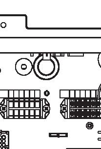
47 5 V Y 5
GUIDELINES FOR CONNECTION TO FTP SERVER TO TRANSFER PRINTING DATA
 GUIDELINES FOR CONNECTION TO FTP SERVER TO TRANSFER PRINTING DATA What is an FTP client and how to use it? FTP (File transport protocol) - A protocol used to transfer your printing data files to the MAFRAPRINT
USER'S MANUAL FAN MOTOR DRIVER FMD-02
 USER'S MANUAL FAN MOTOR DRIVER FMD-02 IMPORTANT NOTE: Read this manual carefully before installing or operating your new air conditioning unit. Make sure to save this manual for future reference. FMD Module
Název společnosti: VPK, s.r.o. Vypracováno kým: Ing. Michal Troščak Telefon: Datum:
 Pozice Počet Popis 1 SCALA2 3-45 A Datum: 2.7.217 Výrobní č.: 98562862 Grundfos SCALA2 is a fully integrated, self-priming, compact waterworks for pressure boosting in domestic applications. SCALA2 incorporates
Název společnosti: VPK, s.r.o. Vypracováno kým: Ing. Michal Troščak Telefon: Datum:
 Počet 1 SCALA2 3-45 A Datum: 2.7.217 Výrobní č.: 98562862 Grundfos SCALA2 is a fully integrated, self-priming, compact waterworks for pressure boosting in domestic applications. SCALA2 incorporates integrated
DATA SHEET. BC516 PNP Darlington transistor. technický list DISCRETE SEMICONDUCTORS Apr 23. Product specification Supersedes data of 1997 Apr 16
 zákaznická linka: 840 50 60 70 DISCRETE SEMICONDUCTORS DATA SHEET book, halfpage M3D186 Supersedes data of 1997 Apr 16 1999 Apr 23 str 1 Dodavatel: GM electronic, spol. s r.o., Křižíkova 77, 186 00 Praha
Litosil - application
 Litosil - application The series of Litosil is primarily determined for cut polished floors. The cut polished floors are supplied by some specialized firms which are fitted with the appropriate technical
INSTALLATION MANUAL. Indoor unit for air to water heat pump system EKHBRD011ABV1 EKHBRD014ABV1 EKHBRD016ABV1 EKHBRD011ABY1 EKHBRD014ABY1 EKHBRD016ABY1
 INSTLLTION MNUL EKHBRD0BV EKHBRD04BV EKHBRD06BV EKHBRD0BY EKHBRD04BY EKHBRD06BY EKHBRD0CV EKHBRD04CV EKHBRD06CV EKHBRD0CY EKHBRD04CY EKHBRD06CY 4 5 6 x x x x x 6x 7 x 8 x 9 x 0 x x x x 4 x B 50 E 0 D C
Mechanika Teplice, výrobní družstvo, závod Děčín TACHOGRAFY. Číslo Servisní Informace Mechanika: 5-2013
 Mechanika Teplice, výrobní družstvo, závod Děčín TACHOGRAFY Servisní Informace Datum vydání: 20.2.2013 Určeno pro : AMS, registrované subj.pro montáž st.měř. Na základě SI VDO č./datum: Není Mechanika
SPECIFICATION FOR ALDER LED
 SPECIFICATION FOR ALDER LED MODEL:AS-D75xxyy-C2LZ-H1-E 1 / 13 Absolute Maximum Ratings (Ta = 25 C) Parameter Symbol Absolute maximum Rating Unit Peak Forward Current I FP 500 ma Forward Current(DC) IF
ZÓNOVÉ VENTILY S VRATNOU PRUŽINOU dvoucestné VZP 2XX 230 1P 001 třícestné VZP 3XX 230 1P 001
 Návod na instalaci a použití ZÓNOVÉ VENTILY S VRATNOU PRUŽINOU dvoucestné VZP 2XX 230 1P 001 třícestné VZP 3XX 230 1P 001 CZ verze 1.2 Popis: Zónové ventily s vratnou pružinou jsou určeny do hydraulických
UŽIVATELSKÁ PŘÍRUČKA
 UŽIVATELSKÁ PŘÍRUČKA Plni víry a naděje míříme kupředu. S odhodláním zlepšujeme své dovednosti. Zapomeňte na zklamání, ale nikoli na svůj nevyužitý potenciál. Touha překonat sám sebe a dosáhnout hranice
INSTALLATION MANUAL. Indoor unit for air to water heat pump system EKHBRD011ADV1 EKHBRD014ADV1 EKHBRD016ADV1 EKHBRD011ADY1 EKHBRD014ADY1 EKHBRD016ADY1
 INSTLLTION MNUL EKHBRD0DV EKHBRD04DV EKHBRD06DV EKHBRD0DY EKHBRD04DY EKHBRD06DY 4 5 6 x x x x x 6x 7 x 8 x 9 x 0 x x x x 4 x B 50 E 0 D C HV LV PS PS LV HV >50 >50 LV HV >500 PS PS HV LV >600 PS LV HV
PC/104, PC/104-Plus. 196 ept GmbH I Tel. +49 (0) / I Fax +49 (0) / I I
 / I Fax +49 (0) / I I") E L E C T R O N I C C O N N E C T O R S 196 ept GmbH I Tel. +49 (0) 88 61 / 25 01 0 I Fax +49 (0) 88 61 / 55 07 I E-Mail sales@ept.de I www.ept.de Contents Introduction 198 Overview 199 The Standard 200
E L E C T R O N I C C O N N E C T O R S 196 ept GmbH I Tel. +49 (0) 88 61 / 25 01 0 I Fax +49 (0) 88 61 / 55 07 I E-Mail sales@ept.de I www.ept.de Contents Introduction 198 Overview 199 The Standard 200
UPM3 Hybrid Návod na ovládání Čerpadlo UPM3 Hybrid 2-5 Instruction Manual UPM3 Hybrid Circulation Pump 6-9
 www.regulus.cz UPM3 Hybrid Návod na ovládání Čerpadlo UPM3 Hybrid 2-5 Instruction Manual UPM3 Hybrid Circulation Pump 6-9 CZ EN UPM3 Hybrid 1. Úvod V továrním nastavení čerpadla UPM3 Hybrid je profil PWM
ADDRESS CONVERSION TABLE FOR MANUAL SETTING
 - (06-57) - ADDRESS CVERSI TABLE FOR MANUAL SETTING In the case of a multiple refrigerant system, each refrigerant system should be set an exclusive refrigerant. Conversion table of refrigerant and rotary
ROLZ-2. Portable AV/Conference Center. Assembly Instructions
 1 ROLZ-2 Portable AV/Conference Center Assembly Instructions Rolz-2 Portable AV/Conference Center Part Drawing Description Qty Part Drawing Description Qty Hardware List A 1 ½ Flat Head Screw 2 EA P-1
obal manuálu, asi něco podobného jako u LC 100 asi by to chtělo lepší obrázek!!! FYTOSCOPE FS130 Instruction Guide
 obal manuálu, asi něco podobného jako u LC 100 asi by to chtělo lepší obrázek!!! FYTOSCOPE FS130 Instruction Guide možná tohle trochu zmenšit a dát sem i to varování LED RADIATION co je na další straně
20 ka / 1 s (dle typu cívky) přirozené
 přirozené") KATALOG CATALOGUE 051/03/2013 VÝKONOVÝ REAKTOR NN, NASTAVITELNÝ LOW VOLTAGE POWER REACTOR COIL, ADJUSTABLE pro napětí do 1000 V for voltages up to 1000V TYP LNN ISO 9001:2009 ISO 14001:2005 VŠEOBECNĚ Výkonový
KATALOG CATALOGUE 051/03/2013 VÝKONOVÝ REAKTOR NN, NASTAVITELNÝ LOW VOLTAGE POWER REACTOR COIL, ADJUSTABLE pro napětí do 1000 V for voltages up to 1000V TYP LNN ISO 9001:2009 ISO 14001:2005 VŠEOBECNĚ Výkonový
2N LiftIP. IO Extender. Communicator for Lifts. Version
 2N LiftIP Communicator for Lifts IO Extender Version 2.4.0 www.2n.cz Description The IO extender helps you extend 2N LiftIP with 1 input and 2 outputs. The purpose of the input is to cancel the rescue
USER'S MANUAL FAN MOTOR DRIVER FMD-01, FMD-03
 USER'S MANUAL FAN MOTOR DRIVER FMD-01, FMD-03 IMPORTANT NOTE: Read this manual carefully before installing or operating your new air conditioning unit. Make sure to save this manual for future reference.
TECHNICKÝ LIST řada mechanických odvaděčů kondenzátu AUTODRAIN TECHNICAL DATA SHEET for mechanical autodrain equipment AUTODRAIN
 Popis: Nádoba s mechanickým plovákem k odstraňování pevných nečistot, vody, aerosolů, uhlovodíků, prachu oddělených separátory KING AIR se systémem stlačeného vzduchu. Rozdělení dle využití instalace:
Uživatelská příručka. USB Charger UCH20
 Uživatelská příručka USB Charger UCH20 Obsah Úvod...3 USB Charger popis... 3 Používání nabíječky USB... 4 Nabíjení zařízení... 4 Právní informace... 5 Declaration of Conformity...6 2 Úvod USB Charger popis
Size / Světlost : DN 1/4 to 4 / DN 1/4 až 4
 Size / Světlost : 1/4 to 4 / 1/4 až 4 Ends / Konce : Threaded BSP / Závitové BSP Min. Temperature / Minimální teplota : -20 C Max. Temperature / Maximální teplota : +180 C Max. Pressure / Maximální tlak
 11.12. 100 ΕΙΣΟΔΟΣ = E / ENTRANCE = E = = 1174 550 ΤΥΠΟΠΟΙΗΜΕΝΟ ΚΥ = 2000 (ΕΠΙΛΟΓΗ: 2100) / CH STANDARD = 2000 (OPTIONAL: 2100) 243 50 ΚΥ/CH + 293 ΚΥ/CH +103 100 ΚΥ /CH 6 11 6 20 100 0,25 ΚΑ (CO) + 45
2N Voice Alarm Station
 2N Voice Alarm Station 2N Lift1 Installation Manual Version 1.0.0 www.2n.cz EN Voice Alarm Station Description The 2N Voice Alarm Station extends the 2N Lift1/ 2N SingleTalk with an audio unit installed
Hi-Res Audio/DNC Headset MDR-NC750
 Uživatelská příručka Hi-Res Audio/DNC Headset MDR-NC750 Obsah Začínáme...3 Úvod...3 Přehled... 3 Základy práce...4 Nošení náhlavní soupravy...4 Připojení náhlavní soupravy k vašemu zařízení... 4 Nastavení
SERVISNÍ MANUÁL PEGAS 250 E CEL OVO SERVICE MANUAL PEGAS 250 E CEL OVO
 MG136-1 PEGAS 250 E CEL OVO SERVICE MANUAL page 1 SERVISNÍ MANUÁL PEGAS 250 E CEL OVO SERVICE MANUAL PEGAS 250 E CEL OVO 1. VAROVÁNÍ WARNING UPOZORNĚNÍ Pouze osoba splňující kvalifikaci danou zákonem je
ZB5AV013 bílá signální hlavice Ø22 plná čočka pro integ. LED
 Characteristics bílá signální hlavice Ø22 plná čočka pro integ. LED Doplňky CAD celková šířka CAD celková výška CAD celková hloubka Hmotnost přístroje Označení skříně Označení el. složení Prostředí Stupeň
MSZ-SF15VA MSZ-SF20VA
 Multisplit Inverter / chlazení nebo topení Výhody K zajištění optimálního proudění vzduchu je možné nastavit jeden z pěti stupňů otáček ventilátoru. Pro velmi rychlé dosažení požadovaného mikroklima slouží
RIMINI. Samozavírací hydraulické závěsy Self-closing hydraulic hinges
 3 RIMINI Samozavírací hydraulické závěsy Self-closing hydraulic hinges Bartosini s.r.o. Kancelář: Karvinská 1897, 737 01 Český Těšín tel.: +420 602 322 276; e-mail: bartosini@bartosini.cz WWW.BARTOSINI.CZ
WL-5480USB. Quick Setup Guide
 Quick Setup Guide 1 Czech 7 Install Utility Software Note1: Before installing the utility software, DO NOT inserts the into your computer. If the adapter is inserted already, Windows will detect the adapter
ROLZ-2. Portable AV/Conference Center. Assembly Instructions
 1 ROLZ-2 Portable AV/Conference Center Assembly Instructions Rolz-2 Portable AV/Conference Center Part Drawing Description Qty Part Drawing Description Qty Hardware List A 1 ½ Flat Head Screw 2 EA P-1
GENERAL INFORMATION RUČNÍ POHON MANUAL DRIVE MECHANISM
 KATALOG CATALOGUE RUČNÍ POHONY PRO VENKOVNÍ PŘÍSTROJE, MONTÁŽ NA BETONOVÉ SLOUPY MANUAL DRIVE MECHANISM FOR THE ACTUATION OF OUTDOOR TYPE SWITCHING DEVICES MOUNTED ON THE CONCRETE POLES TYP RPV ISO 9001:2009
INSTALLATION MANUAL PD 0027.01
 INSTALLATION MANUAL PD 0027.01 OUTDOOR MOTOR DRIVE FOR MV DISCONNECTORS ISO 9001:2009 ISO 14001:2005 OHSAS 18001:2008 TYPE SUP a) STORAGE / SKLADOVÁNÍ The packed devices on wooden pallet it is not allowed
Nástěnné jednotky Split Inverter / chlazení nebo topení
 Nástěnné jednotky Split Inverter / chlazení nebo topení Výhody Technologie replace: bez problémů můžete použít stávající R22 vedení chladiva. DC inverterová technologie a ekologické chladivo R410A zajišťuje
ROZM RY A P IPOJENÍ VÍ IVKY HYDROXEUR PEDI-JET
 DN FORMED Brno s.r.o. Hudcova 76a, 612 48 Brno Telefon: +420 541 321 095 Fax: +420 541 321 096 www.dnformed.cz dnformed@dnformed.cz len Asociace výrobc a dodavatel zdravotnických prost edk ROZM RY A P
R40 Podklady pro projektování CZ_2012_07
 R40 Podklady pro projektování CZ_2012_07 2 Technický popis Technické údaje R40/50 R40/65 R40/85 R40/100 R40/120 R40/150 Jmenovitý tepelný výkon max./min. 80 / 60 C kw 45,8/7,6 60,8/10,1 81,1/13,4 92,9/15,6
Připojení internetového modulu econet300 Do regulátoru ecomax 810P3-L TOUCH.
 Připojení internetového modulu econet300 Do regulátoru ecomax 810P3-L TOUCH. Connection of econet300 internet module to ecomax 810P3-L TOUCH Controller. Prosím ověřte verzi softwaru vašeho modulu ecomax.
INSTALLATION MANUAL. Daikin Altherma indoor unit EKHVMRD50AAV1 EKHVMRD80AAV1 EKHVMYD50AAV1 EKHVMYD80AAV1
 INSTLLTION MNUL EKHVMRD50V EKHVMRD80V EKHVMYD50V EKHVMYD80V CE - TITIKTIES-DEKLRCIJ CE - TBILSTĪBS-DEKLRĀCIJ CE - VYHLÁSENIE-ZHODY CE - UYUMLULUK-BİLDİRİSİ CE - IZJV O SKLDNOSTI CE - VSTVUSDEKLRTSIOON
Ventil zpětný Z15.1 DN 10 50, PN 100 400 Piston check valve Z15.1 DN 10 50, PN 100 400
 DN 10 50, PN 100 400 DN 10 50, PN 100 400 Použití Zpětný ventil je samočinná armatura, zamezující zpětnému proudění provozní tekutiny, určená pro vodu, vodní páru, plyny i jiné provozní tekutiny používané
INSTALLATION MANUAL. Indoor unit for air to water heat pump system EKHBRD011AAV1 EKHBRD014AAV1 EKHBRD016AAV1 EKHBRD011AAY1 EKHBRD014AAY1 EKHBRD016AAY1
 INSTLLTION MNUL EKHBRD0V EKHBRD0V EKHBRD06V EKHBRD0Y EKHBRD0Y EKHBRD06Y 5 6 7 x x x x x x x 8 x 9 0 x x x x + + + + + + + Ø5.9 Ø9.5 B 0 D HV LV PS PS LV HV >50 >50 PS LV HV >500 >600 PS LV HV 0 9 9 80
Pokyny k použití. Model-300. Napájecí zdroj. Návod na obsluhu Operating Instructions. se systémem Aquacontrol Napájací zdroj
 Pokyny k použití Model-300 Návod na obsluhu Operating Instructions Napájecí zdroj se systémem Napájací zdroj so systémom Power Supply with System BK 0011900 / PC AQUACONTROL Kryt aquacontrol Kryt aquacontrol
Gymnázium, Brno, Slovanské nám. 7 WORKBOOK. Mathematics. Teacher: Student:
 WORKBOOK Subject: Teacher: Student: Mathematics.... School year:../ Conic section The conic sections are the nondegenerate curves generated by the intersections of a plane with one or two nappes of a cone.
Použití. Application. Field of application. Rozsah použití A.1.1
 Uzavírací ventil V46.2 DN 10 50, PN 100 400 Regulační ventil V40.2 DN 10 50, PN 100 400 Globe valve V46.2 DN 10 50, PN 100 400 Control valve V40.2 DN 10 50, PN 100 400 Použití Uzavírací ventil (V 46.2)
KATALÓGOVÉ LISTY SEZ-KD25-71VAQ. Single split. Inštalačné dáta
 KTLÓGOVÉ LISTY Inštalačné dáta Single split SEZ-KD25-7VQ Kutlíkova 7, Budova TEHNOPOL, 852 Bratislava Telefón: +42 7 845 E-mail: info@dobraklima.sk SEZ SEZ-KD25 7VQ SUZ-K 7V SUZ-K25 35V Kanálové jednotky
INDUCTION HEATING CAPACITORS KONDENZÁTORY PRO INDUKČNÍ OHŘEV
 INDUCTION HEATING CAPACITORS KONDENZÁTORY PRO INDUKČNÍ OHŘEV SCA - 2012-1 CONTENTS OBSAH 03 General technical information Obecné technické informace 04 Medium Frequency Capacitors - water cooled, up to
Uživatelská příručka. Xperia P TV Dock DK21
 Uživatelská příručka Xperia P TV Dock DK21 Obsah Úvod...3 Přehled zadní strany stanice TV Dock...3 Začínáme...4 Správce LiveWare...4 Upgradování aplikace Správce LiveWare...4 Použití stanice TV Dock...5
MCP-16RC, věž pro čištění vzduchu
 Kompaktní filtrační jednotka s vložkami čištěnými pulsy stlačeného vzduchu. Věž pro čištění vzduchu MCP-16RC je kompaktní kazetový filtr pro decentralizované čištění ovdzuší. Znečištěný vzduch se ve spodní
FILTR ZÁVITOVÝ CELONEREZOVÝ Teplota max.-30 C/200 C TYP D PN16 DN1/4-2. Size / Světlost : DN 1/4 to 2 / DN 1/4 až 2 Ends / Konce :
 FILTR ZÁVITOVÝ CELONEREZOVÝ Teplota max.-30 C/200 C TYP D71 137 PN16 DN1/4-2 Size / Světlost : DN 1/4 to 2 / DN 1/4 až 2 Ends / Konce : Female Female BSP / Závitové BSP (vnitřní-vnitřní) Min. Temperature
Instalační návod. Jednotka pro systém tepelných čerpadel vzduch-voda EDHQ011BB6V3 EDHQ014BB6V3 EDHQ016BB6V3 EDHQ011BB6W1 EDHQ014BB6W1 EDHQ016BB6W1
 Jednotka pro systém tepelných čerpadel vzduch-voda EDHQ0BB6V EDHQ0BB6V EDHQ06BB6V EDHQ0BB6W EDHQ0BB6W EDHQ06BB6W EDLQ0BB6V EDLQ0BB6V EDLQ06BB6V EDLQ0BB6W EDLQ0BB6W EDLQ06BB6W EBHQ0BB6V EBHQ0BB6V EBHQ06BB6V
AUTOMATICKÝ DÁVKOVAČ Harvia. Návod na instalaci a použití instructions for installation and Use
 AUTOMATICKÝ DÁVKOVAČ Harvia Návod na instalaci a použití instructions for installation and Use 15122011 CZ EN 1. OBECNÉ INFORMACE 1. GENEraL Účelem Harvia automatického dávkovače je aplikovat vodu a směs
Izolační manipulační tyče typ IMT IMT Type Insulated Handling Rod
 KATALOG CATALOGUE 024/09/2011 IZOLAČNÍ MANIPULAČNÍ TYČ INSULATED HANDLING ROD TYP IMT KOVOVÁ MANIPULAČNÍ TYČ METALLIC HANDLING ROD TYP KMT ISO 9001:2009 ISO 14001:2005 Izolační manipulační tyče typ IMT
INSTALLATION MANUAL. VRVIII system indoor unit HXHD125A7V1B
 INSTLLTION MNUL CE - TITIKTIES-DEKLRCIJ CE - TBILSTĪBS-DEKLRĀCIJ CE - VYHLÁSENIE-ZHODY CE - UYUMLULUK-BİLDİRİSİ CE - IZJV O SKLDNOSTI CE - VSTVUSDEKLRTSIOON CE - ДЕКЛАРАЦИЯ-ЗА-СЪОТВЕТСТВИЕ CE - IZJV-O-USKLĐENOSTI
Automatika na dávkování chemie automatic dosing
 Automatika na dávkování chemie automatic dosing Swimmingpool Technology Autodos 700 Automatické dávkování Autodos Autodos automatic dosing Autodos 700 je jedno-kanálové zaøízení, pro mìøení a dávkování.
Transportation Problem
 Transportation Problem ١ C H A P T E R 7 Transportation Problem The transportation problem seeks to minimize the total shipping costs of transporting goods from m origins (each with a supply s i ) to n
DC circuits with a single source
 Název projektu: utomatizace výrobních procesů ve strojírenství a řemeslech egistrační číslo: Z..07/..0/0.008 Příjemce: SPŠ strojnická a SOŠ profesora Švejcara Plzeň, Klatovská 09 Tento projekt je spolufinancován
User manual SŘHV Online WEB interface for CUSTOMERS June 2017 version 14 VÍTKOVICE STEEL, a.s. vitkovicesteel.com
 1/ 11 User manual SŘHV Online WEB interface for CUSTOMERS June 2017 version 14 2/ 11 Contents 1. MINIMUM SYSTEM REQUIREMENTS... 3 2. SŘHV ON-LINE WEB INTERFACE... 4 3. LOGGING INTO SŘHV... 4 4. CONTRACT
ELEKTROMOTORY SÉRIE CHT CHT ELECTRIC MOTORS
 ELEKTROMOTORY SÉRIE CHT CHT ELECTRIC MOTORS ÚVOD CHT série elektromotor byla vyvinuta pro p ipojení na p evodovky a z tohoto d vodu mají veškeré mechanické a elektrické charakteristiky p izp sobeny práv
2N Lift8 Audio unit shaft
 2N Lift8 Audio unit shaft Brief Manual Version 3.0.0 www.2n.cz This audio unit is designed for installation on the lift shaft bottom or lift cabin roof, or wherever it is necessary to communicate (during
2N LiftIP. Voice Alarm Station. Communicator for Lifts. Version
 2N LiftIP Communicator for Lifts Voice Alarm Station Version 2.4.0 www.2n.cz Description The 2N Voice Alarm Station is a switch that helps you extend 2N LiftIP with one or more audio units installed on
VENTIL ZPĚTNÝ JEDNODÍLNÝ ZÁVITOVÝ Teplota max.-20 C/150 C TYP C09.Z PN16 DN ¼ -4
 VENTIL ZPĚTNÝ JEDNODÍLNÝ ZÁVITOVÝ Teplota max.-20 C/150 C TYP C09.Z PN16 DN ¼ -4 Size / Světlost : DN 1/4" to 4" / DN 1/4" až 4" Ends / Konce : Female-Female BSP / Závitové, vnitřní-vnitřní závit BSP Min.
AIC ČESKÁ REPUBLIKA CZECH REPUBLIC
 ČESKÁ REPUBLIKA CZECH REPUBLIC ŘÍZENÍ LETOVÉHO PROVOZU ČR, s.p. Letecká informační služba AIR NAVIGATION SERVICES OF THE C.R. Aeronautical Information Service Navigační 787 252 61 Jeneč A 1/14 20 FEB +420
2N Lift8 Audio unit machine room
 2N Lift8 Audio unit machine room Brief Manual Version 3.0.0 www.2n.cz The machine room audio unit is intended for installation in the machine room or as an intercom solution located in the reception.
Specifications AR5500
 Specifications AR5500 Easy Filter Plus Triangle Design Wi-Fi Control - Samsung SmartThings Model Name AR07NXWSAURNEU AR09NXWSAURNEU AR12NXWSAURNEU Power Supply Φ, #, V, Hz 1, 2, 220~240, 50 1, 2, 220~240,
Návod na použití, montáž a údržbu Třícestný zónový kulový ventil s pohonem VZK 3xx - 230-1P - 001
 ávod na použití, montáž a údržbu Třícestný zónový kulový ventil s pohonem VZK 3xx - 230-1P - 001 CZ verze 1.0 1 POUŽITÍ Ventily s pohonem řady VZK 3xx - 230-1P mohou být použity ve spojení s jakýmkoliv
SERVICE MANUAL PEGAS 250 E CEL SERVISNÍ MANUÁL PEGAS 250 E CEL
 MG-011-05 PEGAS 250 E CEL SERVICE MANUAL page 1 SERVISNÍ MANUÁL PEGAS 250 E CEL SERVICE MANUAL PEGAS 250 E CEL 1. VAROVÁNÍ WARNING UPOZORNĚNÍ Pouze osoba splňující kvalifikaci danou zákonem je oprávněna
EXACT DS OFFICE. The best lens for office work
 EXACT DS The best lens for office work EXACT DS When Your Glasses Are Not Enough Lenses with only a reading area provide clear vision of objects located close up, while progressive lenses only provide
Instalační manuál. Venkovní jednotka pro tepelná čerpadla vzduch voda ERSQ011AAV1 ERSQ014AAV1 ERSQ016AAV1 ERRQ011AAV1 ERRQ014AAV1 ERRQ016AAV1
 Venkovní jednotka pro tepelná čerpadla vzduch voda ERSQ0V ERSQ0V ERSQ0V ERRQ0V ERRQ0V ERRQ0V ERSQ0Y ERSQ0Y ERSQ0Y ERRQ0Y ERRQ0Y ERRQ0Y 000 B L H 500 500 C (mm) 00 00 00 00 00 500 000 B 50 50 50 500 500
BERGAMO FIRENZE RIMINI. Samozavírače a samozavírací závěsy Floor springs and hinges
 3 BERGAMO FIRENZE RIMINI Samozavírače a samozavírací závěsy Floor springs and hinges Bartosini s.r.o. Kancelář: Karvinská 1897, 737 01 Český Těšín tel.: +420 602 322 276; e-mail: bartosini@bartosini.cz
DVM CHILLER. Installation manual. Module control MCM-A00N
 Installation manual Module control MCMA00N Thank you for purchasing this Samsung air conditioner. Before operating this unit, please read this installation manual carefully and retain it for future reference.
stany A B C D tents VÝBAVA stanů Husky 2005/Husky 2005 tents ACCESSORIES
 VÝBAVA stanů Husky 2005/Husky 2005 ACCESSORIES A B C D E F Voděodolnost Husky Dostatečné vodní sloupce v hodnotě až 6000 mm/cm 2 tropiko a 10000 mm/cm 2 podlážka (dle typu stanu), PU zátěry a podlepené
WORKSHEET 1: LINEAR EQUATION 1
 WORKSHEET 1: LINEAR EQUATION 1 1. Write down the arithmetical problem according the dictation: 2. Translate the English words, you can use a dictionary: equations to solve solve inverse operation variable
Quick Start Guide. Clear. Rychlý průvodce nastavením
 CZ EN Quick Start Guide Clear Rychlý průvodce nastavením Measurement Měření Před Fully prvním charge použitím the blood plně pressure dobijte monitor baterii before přístroje. first use. 1 Rest your bare
TechoLED H A N D B O O K
 TechoLED HANDBOOK Světelné panely TechoLED Úvod TechoLED LED světelné zdroje jsou moderním a perspektivním zdrojem světla se širokými možnostmi použití. Umožňují plnohodnotnou náhradu žárovek, zářivkových
:= = := :=.. := := := := ρ := := α := π α = α = := = :=
 := = := :=.. := := := := ρ := := α := π α = α = := = := := α := α := = := α := := α = = ρ ρ := := := = := = := := := + + := + + := + := := := := + + := + + := + = = = :=.. := η := η := := π = :=.. :=,
Switch on the appropriate breaker and verify that the light is working properly.
 Package contents Name: MONA WALL PC970 wall light 445 Components included with unit: glass shade with light source, 1x metal light body, 1x wall mount, 3x terminal connectors, 2x hex screws M5, 1x hex
Název společnosti: VPK, s.r.o. Vypracováno kým: Ing. Michal Troščak Telefon: Datum:
 Pozice Počet Popis 1 ALPHA2 25-6 18 Výrobní č.: 9799321 AUTOADAPT function automatically finds the best setpoint and thus reduces the energy consumption and setup time. Insulating shells are supplied with
VENTIL ZPĚTNÝ MEZIPŘÍRUBOVÝ PRUŽINOU - CELONEREZOVÝ Teplota max.-20 C/400 C TYP C09 PN 40 DN15-100
 VENTIL ZPĚTNÝ MEZIPŘÍRUBOVÝ PRUŽINOU - CELONEREZOVÝ Teplota max.-20 C/400 C TYP C09 PN 40 DN15-100 Size / Světlost : DN 15 to DN 100 / DN 15 až DN 100 Ends / Konce : Between flanges ISO PN 10/16/25/40
PRO VNITŘNÍ MONTÁŽ TYP VF SULPHUR HEXAFLUORIDE CIRCUIT BREAKERS FOR INDOOR INSTALLATION TYPE VF
 VYPÍNAČE S PLYNEM SF 6 PRO VNITŘNÍ MONTÁŽ TYP VF SULPHUR HEXAFLUORIDE CIRCUIT BREAKERS FOR INDOOR INSTALLATION TYPE VF 7-38 kv, 800-2500 A, 16-40 ka ABB Power Distribution VŠEOBECNĚ Vypínaãe typové fiady
TECHNOLOGIE A EFEKTIVITA. Specialista na prádelenskou technologii od roku1922 Specialists in industrial laundry since 1922
 TECHNOLOGIE A EFEKTIVITA Specialista na prádelenskou technologii od roku1922 Specialists in industrial laundry since 1922 II PROFESSIONAL EQUIPMENT II 201 PROFESSIONAL EQUIPMENT Nová řada vysokoobrátkových
TEPLOVODNÍ KRBOVÉ VLOŽKY HOT-WATER FIREPLACE INSERTS
 TEPLOVODNÍ KRBOVÉ VLOŽKY HOT-WATER FIREPLACE INSERTS www.hakr.cz All for Power of Fire! HAKR B 101 V21 7 11,5 kw 7 10 kw 14 21 kw Účinnost Efficiency HAKR B 102 V15 varianty / variants varianty / variants
INSTALAČNÍ NÁVOD OPERATING INSTRUCTION
 LED PRODISC II + LED PRODISC II MINI + LED PRODISC II MAXI INSTALAČNÍ NÁVOD OPERATING INSTRUCTION 4000944x 4000945x 4000940x 4000941x 4000946x 4000947x Prodisc II Mini Prodisc II Mini + MW senzor Prodisc
Tento materiál byl vytvořen v rámci projektu Operačního programu Vzdělávání pro konkurenceschopnost.
 Tento materiál byl vytvořen v rámci projektu Operačního programu Vzdělávání pro konkurenceschopnost. Projekt MŠMT ČR Číslo projektu Název projektu školy Klíčová aktivita III/2 EU PENÍZE ŠKOLÁM CZ.1.07/1.4.00/21.2146
TECHNICKÝ LIST řada STANDARD, HP, FZ TECHNICAL DATA SHEET for STANDARD, HP, FZ 2018 v1.0
 Popis: Separátory KingAir jsou určeny k odstraňování pevných nečistot, vody, aerosolů, uhlovodíků, pachů ze systému stlačeného vzduchu. Provedení zařízení umožňuje efektivní odstranění >99.9999% vody a
Výukový materiál zpracovaný v rámci operačního programu Vzdělávání pro konkurenceschopnost
 Výukový materiál zpracovaný v rámci operačního programu Vzdělávání pro konkurenceschopnost Registrační číslo: CZ.1.07/1. 5.00/34.0084 Šablona: II/2 Inovace a zkvalitnění výuky cizích jazyků na středních
STORAGE, TRANSPORTATION, HANDLING MANUAL D0141.STHM.01
 STORAGE, TRANSPORTATION, HANDLING MANUAL GENERÁTOROVÉ ROZVÁDĚCÍ SKŘÍNĚ VN - PRIMÁRNÍ ROZVOD, VNITŘNÍ / VENKOVNÍ PROVEDENÍ GENERATOR MV SWITCHGEAR PRIMARY DISTRIBUTION, INDOOR / OUTDOOR DESIGN ISO 9001:2009
âistiã vzduchu / Air Cleaner MF 06, MF 08, MF 10 ada ASISTENT, velikost G 1/8, G 1/4, G 3/8 ASISTENT Series, G 1/8, G 1/4, G 3/8 Sizes
 âistiã vzduchu / Air Cleaner MF 06, MF 08, MF 10 ASISTENT Series, G 1/8, G 1/4, G 3/8 Sizes PouÏití pfiístroj na ãi tûní vzduchu a oddûlení vody (více neï 90 %) Use Device for air cleaning and water separation
SERVICE ADVISORY SA-5A
 V510 PROPELLER TYPE SERIES REPLACEMENT OF BLADE BEARING SEAL VRTULE TYPOVÉ ŘADY V510 VÝMĚNA TĚSNÍCÍ MANŽETY ULOŽENÍ LISTU 1. GENERAL A. This document provides disassembly and assembly procedure in the
NÁVOD K OBSLUZE KOMBINOVANÝ OBUVNICKÝ STROJ BT - 202
 NÁVOD K OBSLUZE KOMBINOVANÝ OBUVNICKÝ STROJ BT - 202 OBSAH I. Hlavní součásti obuvnického stroje. II. Konstrukce III. Schéma elektrického zapojení IV. Instalace a uvedení do provozu V. Obsluha stroje VI.
Vypracováno: Telefon:
 Počet Popis ALPHA2 25-8 8 Výrobní č.: 98649757 Pozn.: obr. výrobku se může lišit od skuteč. výrobku AUTOADAPT function automatically finds the best setpoint and thus reduces the energy consumption and
spa díly spa components jedineèná relaxace Swimmingpool Technology unique relaxation
 spa díly spa components jedineèná relaxace unique relaxation Swimmingpool Technology Masážní èerpadlo "Sta-Rite" -"Sta-Rite" massage pump 0,7 0,55 Výkon m/h Capacity m/h 2 6 2-250 -25-252 0,75,0 27-25
harvia griffin COLOUR LIGHT Control unit Ridici jednotka
 harvia griffin COLOUR LIGHT Control unit Ridici jednotka 13082008 These instructions for installation and use are intended for owners of colour light units and control units and for electricians responsible
 If there is any inconsistency of weather forecast between Local Weather Station and this unit, the Local Weather Station's forecast should prevail. The trend pointer displayed on the LCD indicates the
1-AYKY. Instalační kabely s Al jádrem. Standard TP-KK-133/01, PNE 347659-3. Konstrukce. Použití. Vlastnosti. Installation cables with Al conductor
 Instalační kabely s Al jádrem Installation cables with Al conductor Standard TP-KK-133/01, PNE 347659-3 4 3 2 1 Konstrukce Construction 1 Hliníkové jádro Aluminium conductor 2 Izolace PVC 3 Výplňový obal
1. ROZLIŠENÍ CS CU-05 a CS CU-05C
 - 1 Evidenční číslo: MG 004-01 Stroj / podskupina: Vodní chlazení Počet stran: 6 Počet příloh: Kopie č.: Vypracoval: Pavel Mastný Kontroloval: Holý Schválil: Holý Podpis: Podpis: Podpis: Datum: 9.2.2009
Hama GmbH & Co KG D-86651 Monheim/Germany. www.hama.com 6 7052312/06.09
 d Die Konformitätserklärung nach der R&TTE Richtlinie 99/5/EG finden Sie unter www.hama.com g See www.hama.com for declaration of conformity according to R&TTE Directive 99/5/EC guidelines f La déclaration
INSTALLATION MANUAL. Unit for air to water heat pump system EDHQ011BB6V3 EDHQ014BB6V3 EDHQ016BB6V3 EDHQ011BB6W1 EDHQ014BB6W1 EDHQ016BB6W1
 INSTALLATION MANUAL EDHQ0BB6V EDHQ0BB6V EDHQ06BB6V EDHQ0BB6W EDHQ0BB6W EDHQ06BB6W EDLQ0BB6V EDLQ0BB6V EDLQ06BB6V EDLQ0BB6W EDLQ0BB6W EDLQ06BB6W EBHQ0BB6V EBHQ0BB6V EBHQ06BB6V EBHQ0BB6W EBHQ0BB6W EBHQ06BB6W
Czech Republic. EDUCAnet. Střední odborná škola Pardubice, s.r.o.
 Czech Republic EDUCAnet Střední odborná škola Pardubice, s.r.o. ACCESS TO MODERN TECHNOLOGIES Do modern technologies influence our behavior? Of course in positive and negative way as well Modern technologies
BD250NE305 BD250SE305
 ENGLISH ÈESKY INSTRUCTIONS OR USE, NÁVOD K POU ITÍ SWITCHING UNIT SPÍNACÍ BLOK BD5NE35 BD5SE35 BD5NE35 BD5SE35 OD-BHD-KS x CS-BD-A OD-BD-MS Installation, service and maintenance of the electrical equipment
ZB5AG6 ovl. hlavice otočná Ø22 2-polohy s návratem Ronis 455
 Technický produktový list Parametry ZB5AG6 ovl. hlavice otočná Ø22 2-polohy s návratem Ronis 455 Hlavní parametry Řada výrobků Harmony XB5 Typ produktu nebo součásti Hlava pro přepínač ovládaný klíčem